

Page 1
For safe use of system and to prevent product failure or accident, please read this
Ver. H_R1_1.1_ENG
manual carefully before use.
Page 2

Before Usage
This product has been designed and manufactured to assure personal safety. Improper use
can result in electronic shock or fire hazard. The safeguards incorporated in this product will
be protected you if you observe the following procedures for installation, use, and servicing.
This product does not contain any parts that can be repaired by user.
CAUTION
It is strongly recommended that you read this manual and use the product in a proper way
The following might cause a fire
◈ Avoid placing the unit near direct sunlight, hear source such as a heater, etc.
◈ Do not share the outlet with the other appliances. It might cause an abnormal heating and a fire.
◈ When smoke goes up or when you smell a strange smell, stop using the unit and turn the unit off by
unplugging the power cable and contact the customer service center.
◈ Place the unit at a distance from a hear source. It is in danger of a fire.
◈ Don’t put burning material such as a flammable spray, etc. It may cause a fire.
◈ Don’t install the unit at a dusty place. It may cause a fire.
◈ Plug the unit firmly not to be shaky. If the plug is not safely inserted into the outlet,
it may cause a fire.
◈ When the multi-outlet is used, don’t use several appliances at the same time.
The abnormal heating of the outlet can cause a fire.
◈ Don’t damage, modify, bend, twist, pull, stick, or heat the power code and the plug.
◈ If the plug is loose in the outlet, don’t use. It can cause a fire or an electric shock.
◈ Don’t insert the metals such as a coin, a hair pin, a piece of iron, etc., or flammable material
such as a paper, a matchstick, etc. in the product. It can cause a fire or an electric shock.
2
Page 3

CONTENTS
1. Summary
Feature …………………………………………………………………………………………………… 6
2. Installation
∙ Contents ………………………………………………………………………………………………… 7
∙ Rear panel ……………………………………………………………………………………………… 8
∙ Video Input……………………………………………………………………………………………… 9
∙ Loop Throughout put………………………………………………………………………………… 10
∙ VGA output …………………………………………………………………………………………… 10
∙ RS-485 connection (PTZ camera)………………………………………………………………… 10
∙ RS-485 (Ext. keyboard connection)……………………………………………………………… 11
∙ Alarm out connection ………………………………………………………………………………… 11
∙ Sensor connection …………………………………………………………………………………… 11
∙ RJ-485 port …………………………………………………………………………………………… 12
∙ USB port ……………………………………………………………………………………………… 12
∙ How to call Setup menu…………………………………………………………………………… 12
3. System configuration
∙ Front panel button …………………………………………………………………………………… 13
∙ Front direction key …………………………………………………………………………………… 16
∙ Mouse…………………………………………………………………………………………………… 17
∙ Icon ……………………………………………………………………………………………………… 17
∙ How to setup the remote controller ID …………………………………………………………… 18
4. System configuration
∙ Information ……………………………………………………………………………………………… 20
∙ Date / Time ……………………………………………………………………………………………… 21
∙ Password ………………………………………………………………………………………………… 22
∙ Disk Manager …………………………………………………………………………………………… 23
∙ Upgrade ………………………………………………………………………………………………… 24
∙ Button Setup …………………………………………………………………………………………… 25
∙ Default Setting ………………………………………………………………………………………… 26
∙ Configuration …………………………………………………………………………………………… 26
∙ Log out …………………………………………………………………………………………………… 27
5. Record
∙ Record……………………………………………………………………………………………………… 27
∙ Schedule Record………………………………………………………………………………………… 28
6. N/W Setup
∙ IP Address………………………………………………………………………………………………… 31
∙ DDNS Option……………………………………………………………………………………………… 33
∙ E-Mail
Setup………………………………………………………………………………………………………… 34
∙ E-Mail Notification……………………………………………………………………………………… 35
7. Camera Setup
3
Page 4

∙ Camera Setup…………………………………………………………………………………………… 36
∙ Camera Title…………………………………………………………………………………………… 37
∙ PTZ Setup……………………………………………………………………………………………… 37
∙ PTZ Touring…………………………………………………………………………………………… 39
∙ How to use PTZ……………………………………………………………………………………… 40
∙ Serial port setup……………………………………………………………………………………… 44
8. Display setup
∙ OSD……………………………………………………………………………………………………… 45
∙ Split Mode……………………………………………………………………………………………… 45
∙ Display…………………………………………………………………………………………………… 50
9. Event Setup
∙ Sensor …………………………………………………………………………………………………… 50
∙ Alarm …………………………………………………………………………………………………… 52
∙ Motion Detection ……………………………………………………………………………………… 53
∙ Internal buzzer ……………………………………………………………………………………… 54
∙ SPOT OUT……………………………………………………………………………………………… 55
∙ Audio …………………………………………………………………………………………………… 56
10. Search
∙ Search …………………………………………………………………………………………………… 57
∙ Calendar search..……………………………………………………………………………………… 58
∙ Date/Time search .…………………………………………………………………………………… 59
∙ Event search …………………………………………………………………………………………… 59
∙ Go To First / Go To Last..…………………………………………………………………………… 60
∙ Search control ………………………………………………………………………………………… 60
∙ Back-up ………………………………………………………………………………………………… 61
11. Appendix……………………………………………………………………………………………… 64
4
Page 5

Feature
Contents
HDD fixing screw
1 — Summary
This Stand Alone Digital Video Recorder is capable of high quality of video and audio data
recording and provides various ways of data search by Calendar, Date/Time and event. Also
the system allows remote user to access in order to monitor and control multiple local DVRs
via TCP/IP / LAN connection.
Main features
(1) High resolution live display
(2) Easy installation and operation
(3) Motion detection record
(4) Sensor and Alarm outputs
(5) Reserved recording (Motion, Sensor/Alarm and time selected record)
(6) Network control via Dynamic IP
(7) NTSC / PAL compatible
(8) Highest data compression of H.264 technology
(9) Data backup to USB memory stick or DVD R/W
Application
(1) Bank, ATM unit, Supermarket, Convenient store and other public places.
(2) Private homes, Apartment, Jewelry shop, Commercial compound and other places
where it needs anti-theft surveillance system.
(3) Warehouse, Production line and other places where evidence is needed after any
event happened and to analyze the situation.
(4) Where to monitor sites remotely
2 — Installation
5
Program CD
Page 6
Rear panel
DIGITAL VIDEO
Battery
controller
Size :
1.5V X
2EA
for
remote
AAA
Adaptor
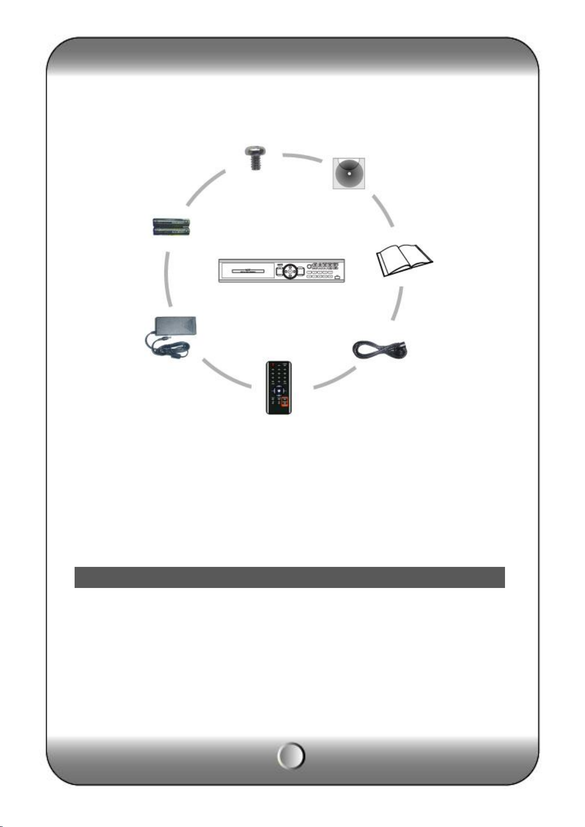
Accessories.
ㆍ Digital Video
Recorder (1EA)
ㆍ HDD Fixing screw
(8pcs)
ㆍ Program CD (1EA)
ㆍ Manual (1EA)
ㆍ Power code (1EA)
ㆍ Remote controller)
ㆍ Battery AAA (1.5V 2EA)
ㆍ Adaptor (1EA)
[Note] Check the accessories before use.
6
Page 7
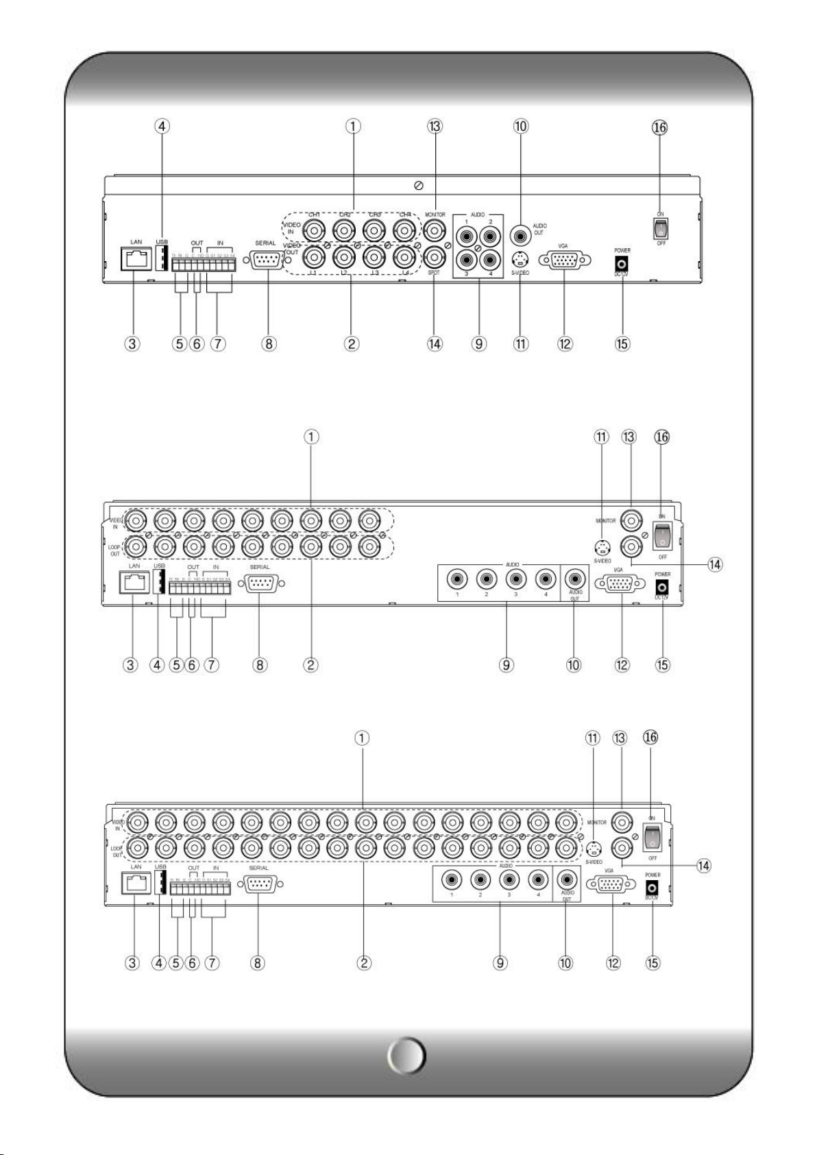
( KVR-H410AN )
( KVR-H920AN )
( KVR-H1640AN )
7
Page 8
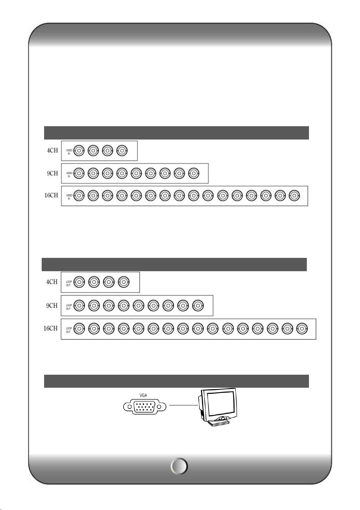
VGA Output
Video Input
Loop Through Out put
[1] Video Input [2] Loop Through [3] RJ-45(Ethernet) [4] USB 2.0 port
[5] RS-485 [6] Alarm output [7] Sensor Input [8] Serial Port (RS-232)
[9] Audio Input [10] Audio output [11] S-Video [12] VGA Out
[13] Composite Out [14] SPOT OUT [15] Power Input [16] Power switch
Connect video cable from camera to the BNC connector.
Loop out for each camera image without any image processing or disturbance.
Connect the PC monitor (LCD / CRT).
8
Page 9
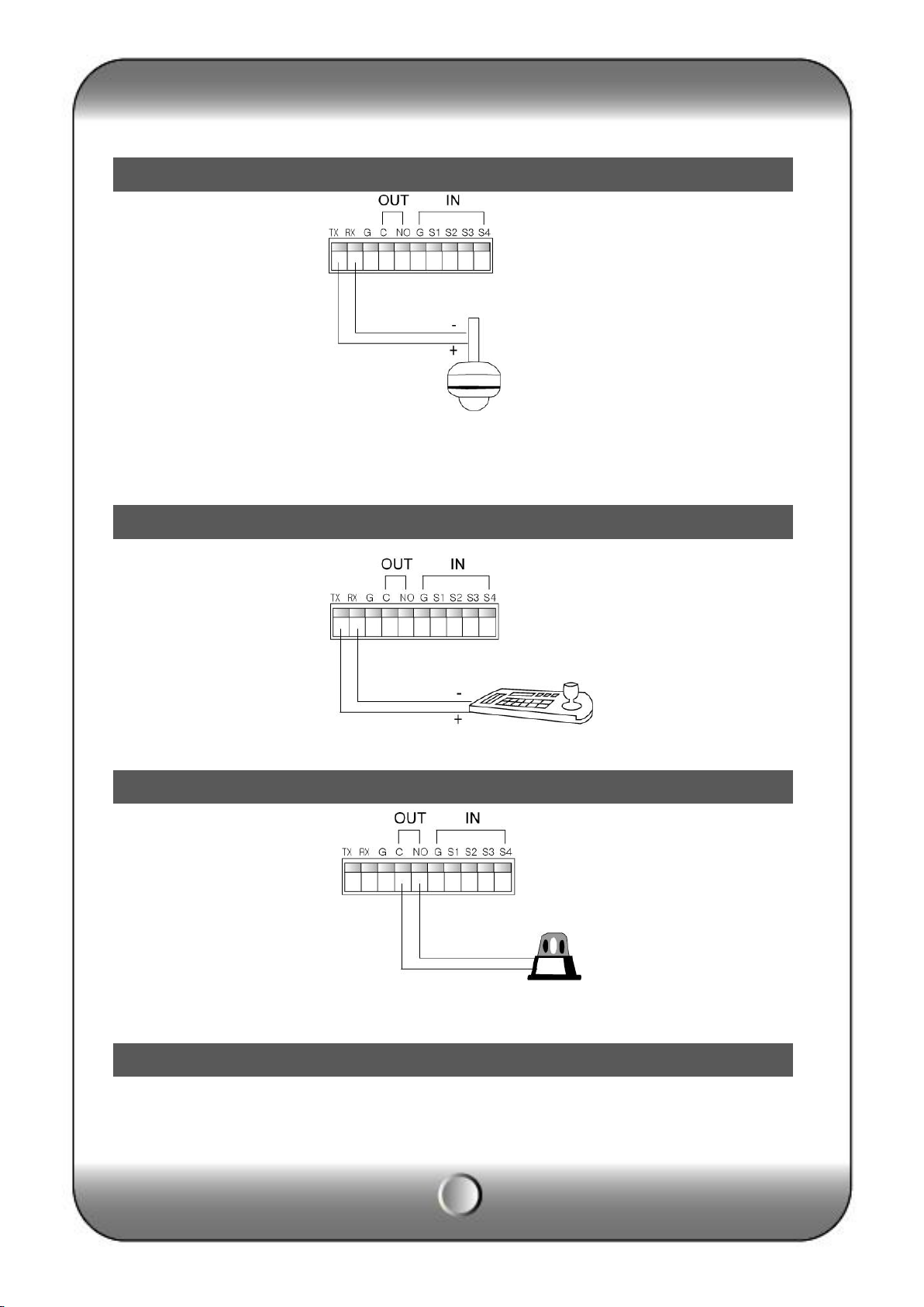
RS-485 connection (PTZ camera)
RS-485 (External keyboard connection)
Alarm out connection
Sensor connection
PTZ Camera
Connect the PTZ camera which is supporting its protocol as per the above diagram.
Connect the external keyboard that should be purchased by the DVR manufacturer.
DVR supports 1 alarm output as above diagram.
9
Page 10
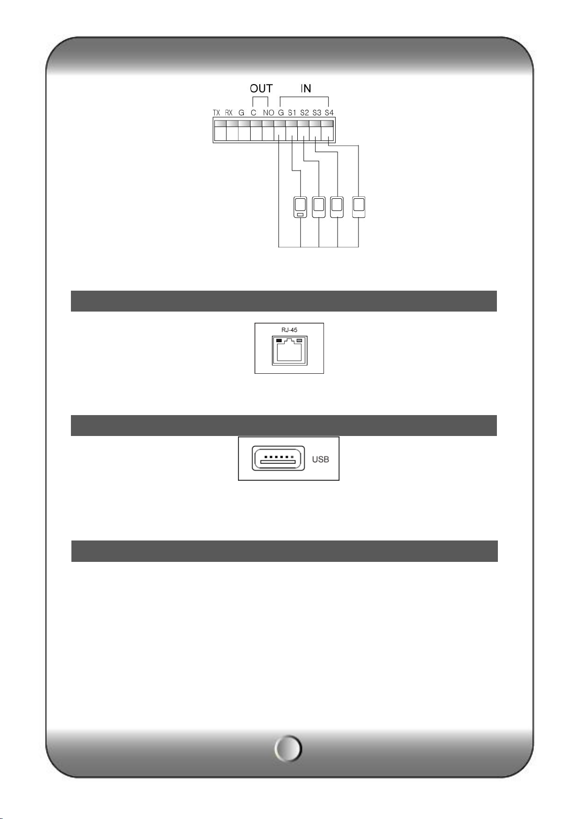
RJ-45 port (Internet connection)
USB port
How to call Setup menu
DVR supports 4 Sensor input as above diagram.
The network connection can be made through the 10/100/1000Mb Ethernet connector by RJ-
45.
DVR supports two USB 2.0 port on front and rear panel for mouse control, firmware upgrade
and backup use.
DVR can be operated by using front buttons, remote controller and mouse.
∙ By front button
Press “MENU” button.
∙ By remote controller
Press “MENU” button on the controller.
∙ By mouse
Click the right button of mouse.
10
Page 11
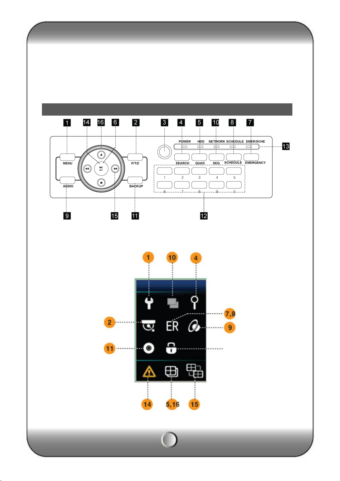
Front panel button
3 — System configuration
(Front button)
(Mouse menu icon)
11
Page 12
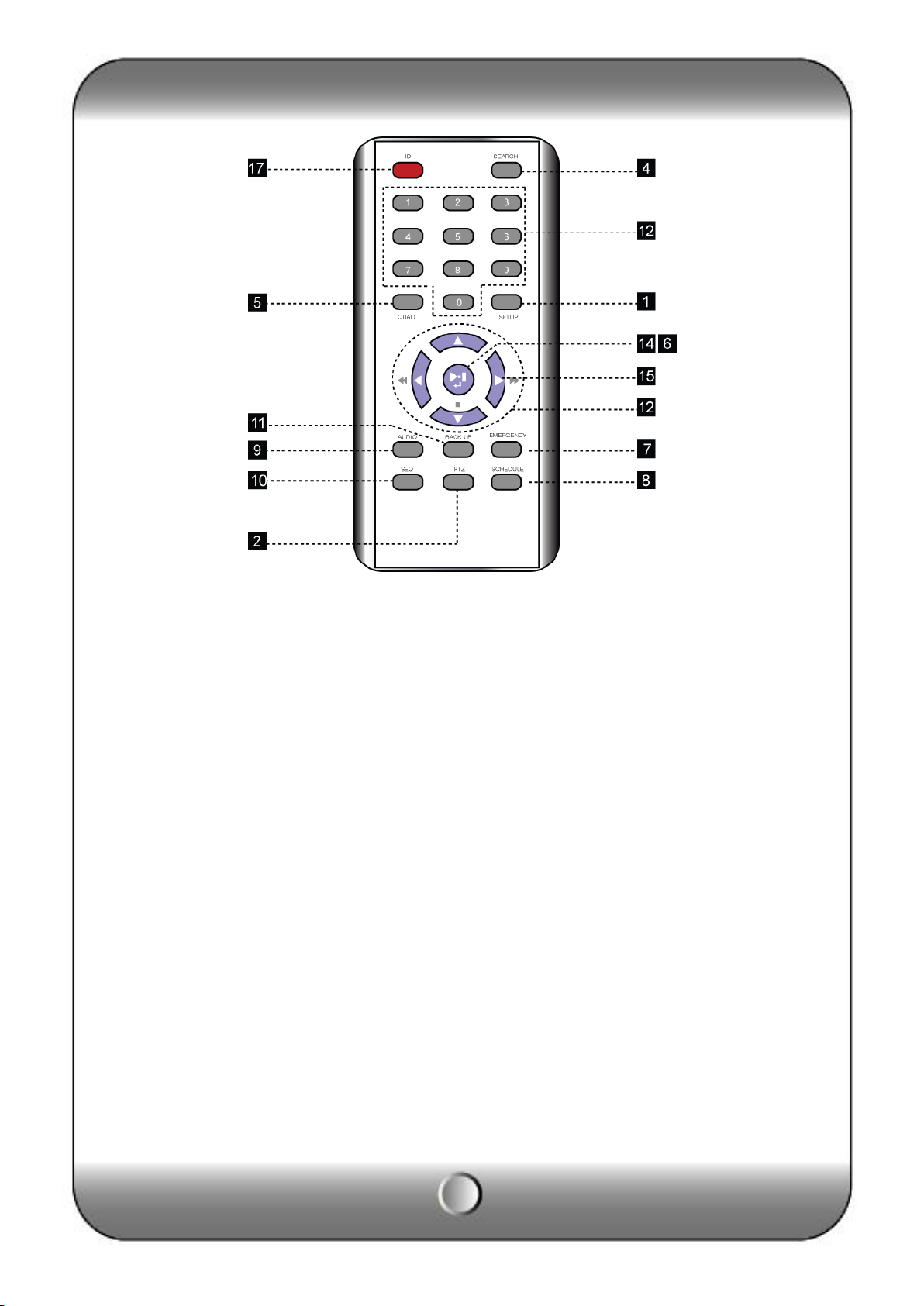
(Remote controller)
[1] MENU
· Call main menu
· Move back to previous menu
[2] PTZ
Button to call PTZ controller menu, PTZ channel must be selected as full screen first.
[3] IR Receiver
Receive the IR signal from remote controller.
[4] SEARCH
Call search menu to playback record image.
[5] QUAD
Switch to multi-channel mode.
[6] LOG OUT(KEYLOCK)
• Using front button or remote controller, press and hold (about 4 sec) to log out.
• Using mouse, click the “LOCK” icon then front button operation is restricted. (Key lock)
[7] SCHEDULE RECORD
Press button to start scheduled recording in emergency record model.
[8] EMERGENCY RECORD
In case of emergency, press “EMERGENCY” button to star recording forcibly regardless
of the recording schedule.
[9] AUDIO
12
Page 13

Select an audio channel.
[10] AUTO SEQUENCE
To display each camera in sequence, display duration is selectable in DISPLAY menu.
[11] BACKUP
Call backup menu to start recorded data archiving to external media.
[12] Channel / Numeric button
Refer to the “Front direction button” page.
[13] LED
LED shows the status of operating.
• POWER : Highlight when power is on.
• RECORD : Highlight when DVR is recording.
• NETWORK : Highlight when DVR is connected by network.
• SCHEDULE : Highlight when DVR is recoding on scheduled mode.
• EMERGENCY : Highlight when DVR is recording on emergency mode.
[14] ERROR LIST
In case of system error, the error icon appears on screen with beep sound. Press
“ENTER” button to see
the list and to stop beep sound.
Icon will be shown in the status bar.
• Main Disk1 Error : 1st HDD error.
• Mirror Disk Error : “Mirror Disk” HDD error.
(Unless use Mirror disk, message “Main Disk2 Error” will be shown)
• DNS Connection Error : Dynamic IP service fail.
• SMTP Connection Error : “E-mail notification” fail.
• Disk Full : Hard disk drive is full.
[15] SPLIT GROUP SETTING
In the split group, press “▶” button to change a channel on each group.
[16] CHANGING SPLIT MODE
Press to change for various split mode.
[17] ID
To control several DVRs using one remote controller, assign the ID to DVR and remote
controller.
13
Page 14
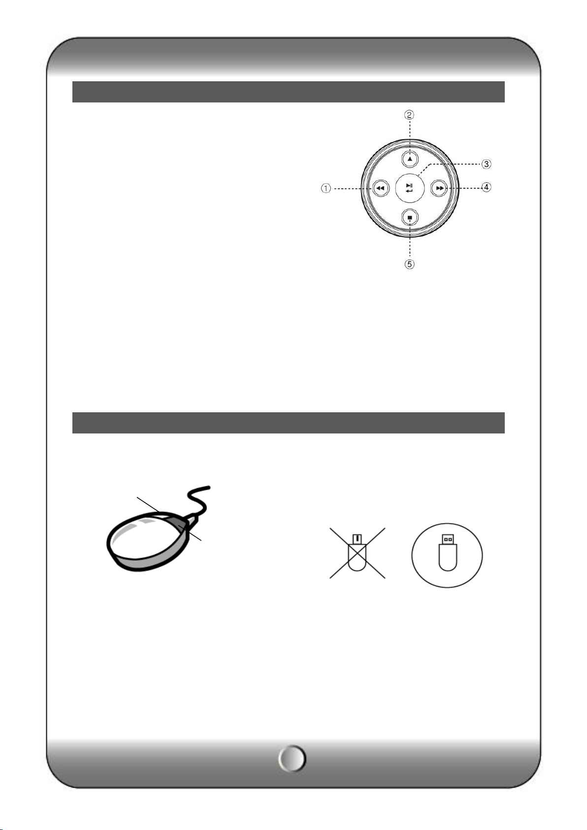
Front direction key
Mouse
[1] Left button
∙ Menu move to left
∙ Reverse playback speed control
[2] Upper button
∙ Menu move to up
∙ Change split mode in live
[3] Playback and Confirmation button
• Confirm the configuration in setup menu.
• Play / Pause button in search mode.
• Log out (Press more than 2 second)
• Stop beep and show error list when system error.
[4] Right button
∙ Menu move to the right.
∙ Playback speed control
[5] Lower button
∙ Menu move to down
• Stop button in search mode.
PC mouse can be used to operate and control all the system function, this feature is for the
users who are familiar to PC environment.
Selection Click right side mouse button to open main menu.
Click selection button to use ◀, ▶, ▲, ▼ on
each configuration..
Menu call and
Move back to previous
PS/2 MOUSE USB MOUSE
14
Page 15
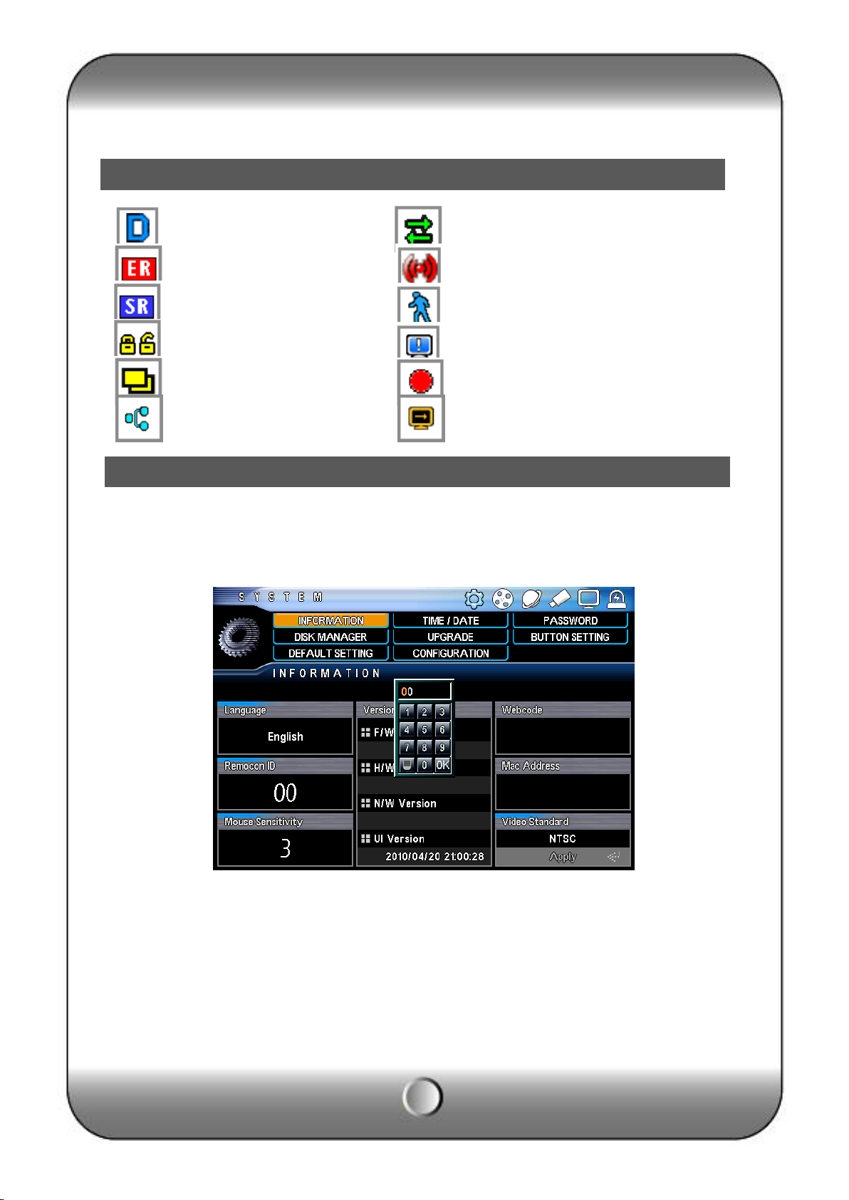
Icon
How to setup the remote controller ID
Daylight Saving Time Network connection icon
Emergency recording Sensor recording
Schedule recording Motion detection
Key lock status icon Video Loss
Auto sequence icon Record icon
Internet connection icon De-interlace icon
In order to use remote controller, the ID must be same both DVR and remote controller.
By assigning DVR ID, it allows the user to control multiple DVRs with one remote
controller.
[1] Check current system ID and can be changed by user. (Factory default ID: “0”)
Menu > Information > Remote ID (Range: 0 ~ 99 )
System ID must be configured on DVR system menu. It cannot change DVR system on
remote controller.
[2] How to use remote controller
ID must be identified between remote controller and system. Otherwise remote
controller cannot recognize DVR correctly.
15
Page 16
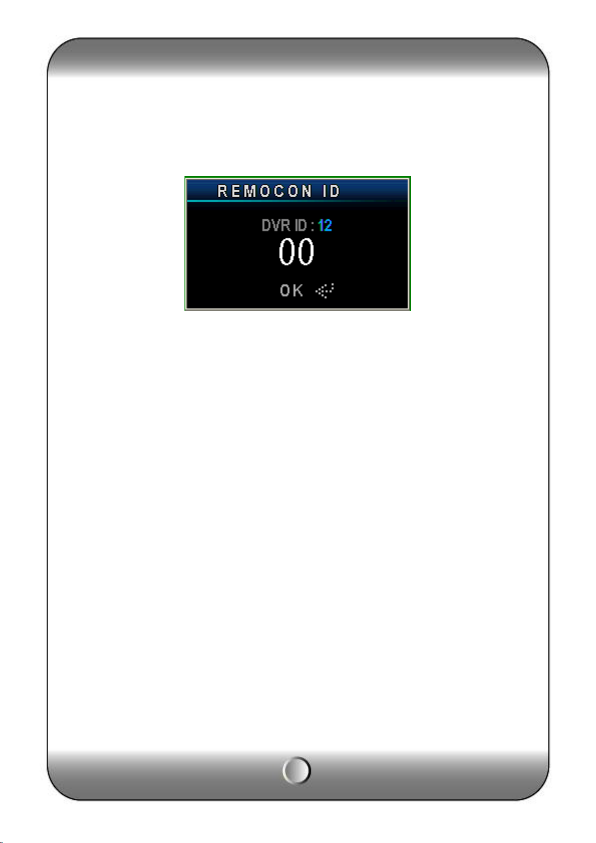
[3] Remote controller ID menu displays as above image when you click ID button of
remote controller.
∙ DVR ID : It displays current ID of the system.
∙ “00” : Input the same ID number of DVR and press “Confirm”
[Note]
∙ The DVR can be controlled once the ID between the DVR and remote controller is same so,
if the DVR is not working, please check the ID.
16
Page 17
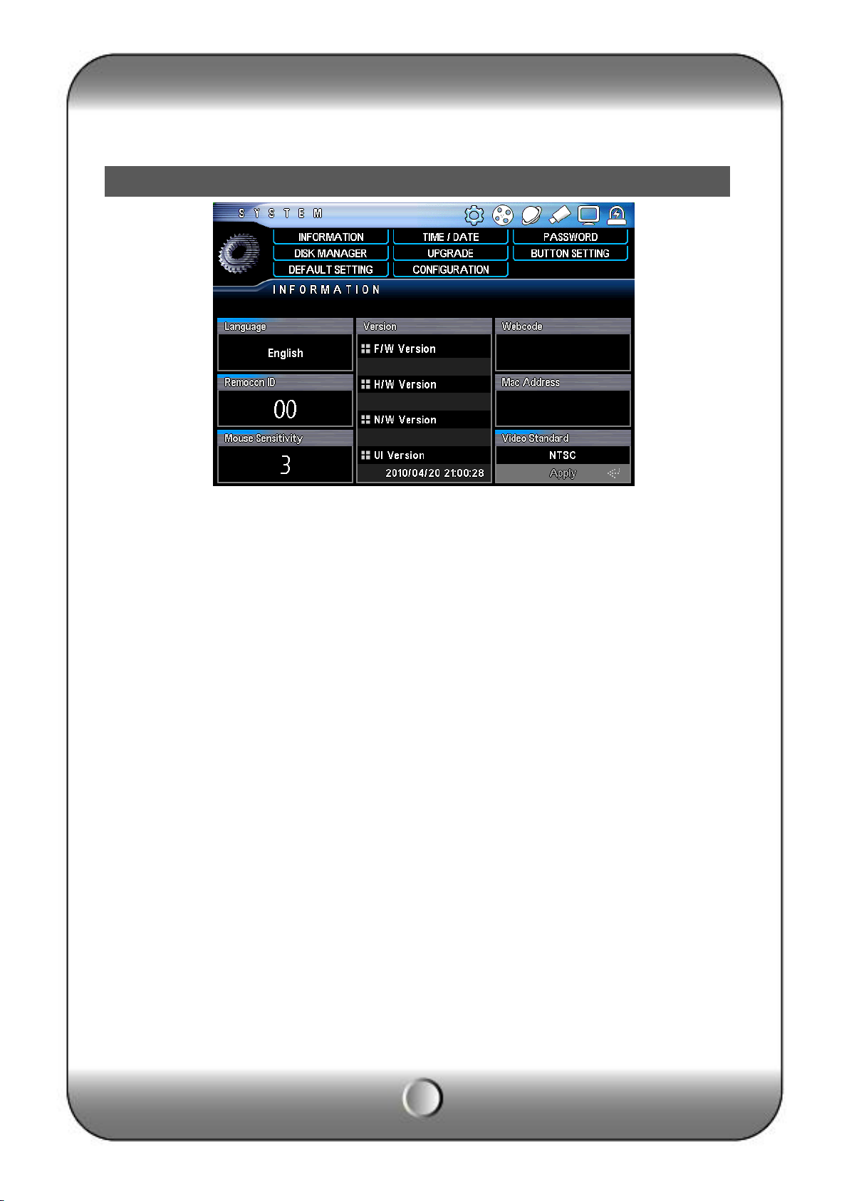
INFORMATION
4 — System configuration
[1] Language : Select a language
[2] REMOCON ID : Assign the ID of remote controller, so that user can separately control
multiple
DVR unit with one controller. (ID range: 0 ~ 99)
[3] MOUSE Sensitivity : Mouse sensitivity level can be adjusted at user’s convenience.
(Basic Level 1; Slow speed, Level 1 < Level 2 < Level 3 to increase reaction speed.)
[4] Version
• H/W Version : Hardware version
• S/W Version : Software version
• N/W Version : Network version
• UI Version : User Interface version
[5] Web Code : Identification for remote monitoring of dynamic IP user.
Please refer to the CMS manual or Network menu.
[6] Mac Address : MAC address of system
[7] Video Standard : Select a video standard of your region then press “APPLY”.
( System is reboot automatically and applied)
17
Page 18
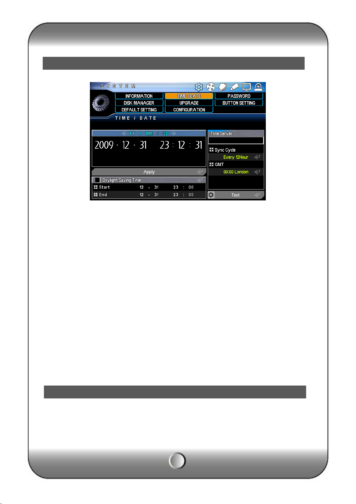
Date/Time
Password
[1] YY / MM / DD : select a display format.
• ASIA : YYYY/MM/DD --> 2006/05/31
• US : MM/DD/YYYY --> 05/31/2006
• EURO : DD/MM/YYYY --> 31/05/2006
[2] Daylight Saving Time : It is commonly called as “Summer time”. During the period,
user can change system time 1 hour early or late.
[3] Time Server : It helps time set of DVR automatically by synchronization of time server
service.
• Time server : Input the URL of server
• Sync Cycle : Select the period to syncronize between DVR and time server
• GMT : Select GMT time zone where user located in.
• TEST : Check the connection status of time server.
[Note]
• In case DVR is not connected with internet or time server name is not collect, DVR gives
beep and error message. Press “CONFIRM” button to off sound and see a error message.
• GMT zone and time server name are searched easily on internet browser.
The administrator (Admin) has a whole authority to control the DVR and rest user may be
restricted their authority as per the user authority.
.
18
Page 19

Disk Manager
[1] User ID : Able to input max. 8 user’s account.
[2] User Group : Select a group which is defined by functionality.
∙ admin : Able to use all functions.
∙ power User : Able to use Configuration, Search, Backup.
∙ User : Choose a function to use.
[3] Password : Input the new P/W for the selected ID. (Max. 8 digit)
[Note] Default password of all ID is “11111111”.
[4] Authority : Select a function to allow on each user’s authority.
[5] Camera allocation : Select an allowable camera on each user.
It is the HDD and ODD setup. Since it is closely related to the record, if the setup is wrong, it
may cause the mal functioning.
19
Page 20

UPGRADE
[1] Disk1 : Priority disk drive information..
• Main Disk : Use as a recording disk.
• Mirror Disk : Use as a mirroring disk.
• None : No use.
[2] DISK2 : Secondary disk drive or ODD (CD/DVD-RW) information.
In case of using ODD, “RW Write” info will be shown.
• Main Disk : Use as a recording disk
• Mirror Disk : Use as a mirroring disk
• None : No use.
[3] FORMAT : Initialize a disk drive.
[4] TOTAL : Display total HDD capacity. ( Occupied size / Available size )
[5] Over write: It is to set overwrite option when the HDD is full. System will overwrite from
the
firstly saved data in the HDD.
[6] Auto Delete : The function is to keep recorded data in HDD during only for specified
period. (Range: 1~120days)
[7] CD /DVD RW : Status of installation of CD or DVD writer.
In order to improve system performance or adding new function, firmware upgrade is needed.
[1] F/W Upgrade : In order to upgrade system firmware with USB memory stick, the
firmware file
must be saved in the USB storage first and then insert to DVR to start USB upgrade from
the
20
Page 21

Button Setup
menu.
Copy firmware
USB Memory Stick
[NOTE] Do not turn off power or remove USB stick while backup is being procedure.
Button setup (Front, Mouse, Remote controller and Button beep)
[1] Button Beep : It makes beep sound while the button is pressed.
[2] Auto Key Lock : It prohobits button use.
∙ On : It asks the password for the important buttons.
( Channel button, QUAD button, SEQ button can be used any time )
( When key locked, icon is changed as above picture)
∙ Off : It doen not use this button.
21
Page 22

DEFAULT SETTING
Configuration
• Default Setting : Except major configuration (Network, Password), parameters are
initialized.
• Factory Setting : All parameters are initialized.
• Configuration Upload : Upload a configuration file to DVR.
• Configuration Download : Save a configuration file of DVR.
22
Page 23

Record
LOG OUT
In live mode, press “CONFIRM” button for 4 second to log out.
5. — RECORD
Set up recording resolution, frame and quality on each channel.
1] Pre Recording
In case of event, DVR can record the image priot to 5~6 second from event time.
[2] Water Mark : To protect forgery or edit of image, check a Watermark.
[3] Enable / Disable record : Once click the camera icon, user can select the recordable
channel.
(Enable) (Disable)
[4] Resolution : Select a recording resolution
[5] Frame : Select a recoding speed.
[6] Quality : Select a image quality.
23
Page 24

Schedule Record
[7] Post REC : Duration of event recording.
[8] Audio : Select a channel for audio recording.
(AUDIO RECORD ON) (AUDIO RECORD OFF)
Set up the recording schedule.
[1] Select a channel.
[2] Choose a recording mode and designate the time and date.
Motion : Record when motion detectected.
Sensor : Record when sensor triggered.
Motion+Sensor : Record when mortion detectected or sensor triggered.
Continuous : Record continuously.
Erase : Cancel a parameter.
Clear : Delete all
[3] Once press “CONFIRM” button, event color will be changed.
[4] All : Copy the schedule to all channel.
[5] Holiday : Register a holiday and set up holiday recording schedule.
24
Page 25

Choose a day on the calendar and set up schedule using by direction button and “CONFIRM”
button.
[1] Channel : Select a channel.
[2] Choose a date to register holiday on calendar.
[3] Select a event icon then set the time.
25
Page 26

IP Address
[4] Clear Holiday : To delete registered holiday, select a date using “START” and “FINISH”
and press ”CLEAR”.
[5] Applied channel : To apply configured holiday schedule to all or individual channel.
① Save holiday schedule.
② Apply to all channel
③ Select an individual channel.
6 — N/W Setup
It is the system setup for remote mornitoring or backup and it needs the network setup of
DVR.
The user must know whether their internet is dynamic IP(DHCP) or fixed IP. Please check it
to your ISP before setup.
[NOTE] The difference between the dynamic and fixed IP!
ㆍDynamic IP : The using internet line is common wide for the user. Since doesn’t have the
fixed address, it is hard to connect from the outside. But it is possible if there is the server
which in informing the address.
This DVR supports dynamic IP as well by the separate server management.
ㆍFixed IP : It has the specific and only IP address in the world to connect the internet.
26
Page 27

[1] DHCP : It uses for dynamic IP user (On).
The static IP user does not need the DHCP function (Off)
[2] IP Address : The dynamic IP user does not set it up.
If you use the static IP, input the following information after ask it to ISP.
[Sample]
ㆍIP ADDRESS : 192.168.010.003
ㆍSUBNET MASK : 255.255.255.000
ㆍGATEWAY : 192.168.001.001
ㆍDNS : 168.124.101.002
[3] DDNS address : It is for dynamic IP user, do not change the DDNS address.
Basic using port is 2000( static IP user doesn’t have to care for this)
[NOTE] If dynamic IP user uses the router, the user should do the port forwarding if he uses
the router. The port forwarding function is described on the router manual.
[4] The bandwidth can be selectable as per the network speed for smooth image streaming.
- HIGH : It streams as per the current record setup.
- MIDDLE: It streams middle level from the current record setup.
- LOW: It streams low level from the current record setup.
☞ 3 different level of Bandwidth can be additionally adjustable
[5] Dual stream
∙ Use : Max 120fps can be transmitted through the internet.
∙ Not use: Max 480fps can be transmitted according to the network speed
27
Page 28

DDNS Option
[6] Web Server Port
Since there is Built-in webserver, if you know the IP address, you can direct connect to
DVR through web browser. The default port is 80.
(Example) You can use with fixed IP and DNS service
-Fixed IP.
If the DVR IP is 192.168.010.003, you can simply enter ‘http://192.168.010.003 80’ on
URL, then monitoring program is automatically executing. This connection is possible in
LAN and Fixed IP using condition. If the port is 80, it can be deleted. Other than that, you
have to input the port number to the end of IP address ex) 192.168.010.003 2500(port
number)
-Private DNS user.
• If you use the private DNS service, you have to set the “DDNS OPTION’ menu from
DVR(Please refer to the manual). Input the URL address to the web browser which is joined
to the private DNS homepage. Ex) DYDNS.COM, no-ip.com
It is the web monitoring option using the private DNS service.
DNS
[Notice] Please visit the private DNS home page for the registration.
• DDNS Server : Select the private DNS service.
(Select : DyDns or, no-ip )
• Account/Password/URL : Join the membership after visit the homepage of the private
website and input the ID/Password/URL obtained after joining.
28
Page 29

E-Mail Setup
It notice the event to the user.
E-mail setup
It is the basic setup for e-mail sending. Since it will not send the mail if the setup is wrong,
please be cereful.
[1] Mail server(SMTP SERVER) : Mail sending server. Input the mail server address of user.
Input the send mail(”SMTP) address. If you are not sure, please contact your mail server
manager.
[2] USER PORT : Most mail server use port 25 so, if it doesn‘t work, pleas check the port No.
[3] Account : If you need to enter the ID/Password to send the e-mail, please check.
[4] Mail Address : Input the e-mail address of receiver ( Max. 4 people)
It selects the e-mail sending event.
29
Page 30

E-Mail Notification
[1] Mail Title : Input the mail title.
[2] Interval : If you make the time setup in event cases, the DVR doesn’t send the e-mail
repeatedly during the selected duration. It is to prohibit the mass e-mail
sending in frequent events.
[3] Notification : E-mail sending can be selected as per the event.
• Sensor : It sends the mail in sensor evnt.
• Motion detection: It sends the mail in MD evnt.
• Video loss : It sends the mail in video loss evnt.
• Power on : It sends the mail in power on.
• Password modify : It sends the mail in password is modified.
• HDD ERROR : It sends the mail in HDD error.
30
Page 31

7 — Camera setup
Camera setup
Camera Title
It is the setup of camera usage and color.
[1] Covert : It is the Covert setup.
[2] AGC (Automatic Gain Control) : It setup the automatic gain control of camera to get the
proper bright.
[3] Static gain: It amplify the camera input signal.
[4] Brightness: Bright control
[5] Contrast: Contrast control
[6] Saturation: Black/White control.
The camera title can be input by the virtual keyboard.
31
Page 32

PTZ setup
If you click the channel, virtual keyboard show up.
It is for PTZ camera setup.
• Model : Select the PTZ model.
• ID : Select the PTZ ID. (Refer to the PTZ manual)
Advanced (Detailed PTZ setup)
It is for the PTZ speed control setup.
32
Page 33

PTZ touring
Serial Port
Select the PTZ communication port( RS-232 or RS-485)
Revers Control
▷ PAN : Select the reverse movement of PAN (right and left).
▷ TILT : Select the reverse movement of TILT (up and down).
Speed
▷ Pan Speed : Speed control of right and left
▷ Tilt Speed: Speed control of up and down
▷ Zoom Speed : Speed control of Zoom
▷ Focus Speed : Speed control of focus
▷ IRIS: Iris control
Changed ID
▷ In some PTZ camera, you may not changed the ID manually. In this case, the ID can be
changed from the DVR.
- Click the ID view to see the current ID of PTZ
- Input the new ID to the ‘New ID’ Click ‘APPLY’
[NOTE] PTZ protocol selection
Protocol is PTZ moving driver. The protocol is registered as per the camera model name or
protocol name. Please check whether you PTZ is usable for this DVR.
PTZ touring is moving the saved/memorized position by sequence.
33
Page 34

How to use PTZ
[1] Select Channel.
[2] Select the PTZ preset as per the number and select the speed to move.
[3] Select the moving speed.
[3] Maintain : Select the time to hold the camera movement after camera moved to this
location.
If you call the touring after above setup, the PTZ moves to the saved position by sequence.
How to call the PTZ menu.
The PTZ camera should be installed and selected from DVR.
(1) Menu call from front panel : Select the PTZ camera installed channel and press ‘PTZ’ then,
it will show “+”
34
Page 35

(2) Menu call by mouse : Select the PTZ camera installed channel and click the right button
of mouse and click the PTZ icon as follows then, it will show “+”
(3) Menu call from remote controller : Select the PTZ camera installed channel and press
‘PTZ’ from remote controller then, it will show “+”.
35
Page 36

( PTZ control screen )
How to operate PTZ
(1) Operating in front.
• The camera can be moved by direction key.
• Every time when you press enter, the modes are changing(pan, tilt, zoom, focus) then use
the right and left key for moving.
- P/T : Camera moving.
- Z : Camera zoom-in/out
- F : Focus control.
(2) Operating by mouse
• When you use mouse, drag the mouse from inside to outside. If the mouse is moving far
away from center, the speed become faster.
• By moving the mouse scroll, the menu changes then, select right/left.
- P/T : Camera moving.
- Z : Camera zoom-in/out
- F : Focus control.
36
Page 37

(3) Operating by remote controller
• The camera can be moved by direction key.
• By pressing the ‘enter’ key, the menu changes then, select right/left.
- P/T : Camera moving.
- Z : Camera zoom-in/out
- F : Focus control.
PAN/TILT ADVANCED MENU
Once you call the PTZ menu, if you click it once again, the advanced setup menu shows.
(1) In front button or in remote controller, if you want to change the pop-up location of
advanced menu, move to right/left( If you use mouse, you can drag it. )
(2 It is for camera moving.
37
Page 38

Serial port setup
(3 It is for PTZ maximize or minimize.
(4 It is for Camera focus.
(5) It is for Auto-focus.
(6). If you enter the preset number and press ‘enter’, the camera will move to selected preset
No.
(7) It supports touring as per the preset numbers saved
(12) It is for calling the OSD menu from PTZ itself.
It is the serial port setup for the external device.
38
Page 39

OSD
Split Mode
[1] RS-485: It is for ‘External keyboard’ and ‘PTZ. Since the setup is different as per the
device, please check their manual for Baud Rate / Parity / Stop Bit setup
[2] RS-232: Set up the following information before use.
∙ Baud Rate / Parity / Stop Bit
8 — Display Setup
It setup the displaying on the screen.
[1] Alpha-blending : It setup the transparence of menu.
[2] Window Display : Select the OSD menu to be shown on the screen..
• All : It shows all.
• Camera Title : It displays camera title.
• Split Border : It displays split.
DVR provides the various of split mode when you press the “QUAD” button. You can choose
the split mode and change the channel. Multi split mode is subject to each model.
[Note] If you press the “UP” key in live mode, the split mode is changed and if you press
“RIGHT(direction)” key, the split group is changed.
Select the split mode (16CH)
39
Page 40

16 Split mode(16Ch DVR)
• Auto Loss Skip : It skips video loss
13 Split mode(16Ch DVR)
• Auto Loss Skip : It skips video loss
• 3 sec : Sequencing time selection of divided screen.
• If you click the channel number, you can change the channel order.
10 Split mode(16Ch DVR)
40
Page 41

• Auto Loss Skip : It skips video loss
• 3 sec : Sequencing time selection of divided screen.
• If you click the channel number, you can change the channel order.
9 Split mode(16Ch/9Ch DVR)
• Auto Loss Skip : It skips video loss
• 3 sec : Sequencing time selection of divided screen.
• If you click the channel number, you can change the channel order.
41
Page 42

8 Split mode(16Ch/9Ch DVR)
• Auto Loss Skip : It skips video loss
• 3 sec : Sequencing time selection of divided screen.
• If you click the channel number, you can change the channel order.
6 Split mode(16Ch/9Ch DVR)
• Auto Loss Skip : It skips video loss
• 3 sec : Sequencing time selection of divided screen.
• If you click the channel number, you can change the channel order.
42
Page 43

Display
4 Split mode(16Ch/9Ch/4Ch DVR)
• Auto Loss Skip : It skips video loss
• 3 sec : Sequencing time selection of divided screen.
• If you click the channel number, you can change the channel order.
1Split mode(16Ch/9Ch/4Ch DVR)
• Auto Loss Skip : It skips video loss
• 3 sec : Sequencing time selection of divided screen.
• If you click the channel number, you can change the channel order.
[Notice] Sequencing duration of each channel is possible in single channel mode.
43
Page 44

Sensor
• Normal : It makes the video output as per the display resolution.
• VGA : It is for LCD monitor output.
• Small : Since the output resolution is different as per the LCD, CRT, check whether the
screen shows well.
9 — Event Setup
It shows the sensor connection and setup. It suppoerts 4 sensor input.
* The related camera can be different as per the model(4/9/16Ch).
44
Page 45

Alarm
[1] Sensor Input : Select the sensor usage.
(sensor use) (Sensor not use)
[2] Input Type: Select the sensor input type.
N/Open (NORMAL OPEN) : The contact is normally opened but closed when the signal is
generated.
N/Close (NORMAL CLOSE) : The contact is normally closed but opend when the signal is
generated.
[3] Related camera: Select the camera to be related with sensor. Multi-selection is possible.
(Note; As per the model, the related camera of 4Ch is 4, 9Ch is 9 and 16Ch is 16)
It shows the alarm connection and setup. It supports 1 alarm out.
45
Page 46

Motion Detection
( Motion detection) (Sensor detection) (Video Loss)
The output time continuous as as per the event selected on each channel.
It is the motion detection setup menu. If there is the movement, it makes an event record as
per the area and sensitivity setup.
46
Page 47

[1] CH : Motion detection ON/OFF selection.
[2] Sensitivity : Sensitivity setup.
Before your actual record appliying, please test the response as per the different
sensitivity.
[3] Detection Area
The cursor moving by the direction key and if press “enter”, this block is designated for
motion detection.
* MD selected area : Blue out-line
* MD non-selected area : transparent
* If the movement is detected, the color of that area turns red.
[Apply to all] If you use the following key, you can make apply or release in one button.
“No1” button: Select all.
“No 2” button: Release all
[Using mouse]
Locate the pointer on start point and click the right button then dragging to the ending
point.
47
Page 48

SPOT OUT
INTERNAL BUZZER
( Motion detection) (Sensor detection) (Video Loss)
The output time continuous as as per the event selected on each channel.
It is spot out setup. It can be monitored by the separate monitor such as one channel
displaying, sequencing, event pop-up etc.,
48
Page 49

Audio
• ▷Mode : Select the output mode.
Auto Loss Skip : If there is no video input, it skips from sequencing.
• Spot Mode : It works when the selected event is happened.
- Event : It pop-up the event channel.
- Sequaence : It sequences for all channel as per the designated duration.
- Event + Sequaence : The channel is sequencing in normal time but, if the
- Channel fix: It shows selected channel all the time.
▷ Display time : It is setup for the dwell time during sequencing.
* The dwell time can be selected at Sequence, Event, SEQ+EVENT.
If the microphone is connected to the DVR, you can listen to the audio sound in live or search
mode. The audio listening is possible In muti-screen mode as well.
[1] Menu call : If you select the “AUDIO” during the live or search, the audio out menu show
up. The menu call is possible from the front key, remote controller and mouse.
[2] Audio listening : If you click the ‘speaker’ icon, it is selected or, released.
( Audio listening ) ( No listening)
[3] Audio volume : If the bar moves to right, the volume is increasing.
49
Page 50

Search
[4] AUTO : Audio output is automatic in selected channel.
[5] OFF : Audio listening OFF
10 — Search
It supports the various way of search mode such as Calendar, Date/Time, Event, etc.
[1] How to call menu : Select the “SEARCH” button from the front, remote controller, mouse
menu.
[2] Search mode selection
(1) Calendar search: Search by calendar.
(2) Event search: Search by event.
(3) Date /Time search: Search by specific Date/Time.
50
Page 51

(4) Go to first : It searches the first recorded data on HDD.
(5) Go to last : It searches the last recorded data on HDD.
Calendar serach
It searches by the calendar.
[1] Disk : Select the HDD to search.
[2] If the DVR read the recorded data, it shows it as calendar. Then, select the date.
[3] Select the time.
[4] Select the minutes then, it starts playback.
Date/Time search
If you know the specific date/ Time, input the time to search.
51
Page 52

Search control
[1] Camera : Select the channel to search.
[2] Disk : Select the HDD to search.
[3] Date/Time : input the date/time to search.
Event search
It searches event recorded data.
( The channel display is different as per the 16Ch/9Ch/4Ch DVR)
[1] Camera : Select the channel to search.
[2] Date/Time : input the date/time to search.
[3] Event : Select the event type to search.
[4] Disk : Select the HDD to search.
[5] Click the ‘Search’ button
If you select the event list, it starts to playback.
Go to first / Go to last
It searches the first or last recorded image.
Search button description
[Front direction button]
52
Page 53

Back-up
[1] Playback or Pause
[2] Reverse playback and its speed control ( Only “I” frame is playback in reverse
playback )
[3] Speed control of playback
[4] Stop button( It stops the current function and move to the upper menu)
[Mouse using]
[1] It searches 5 minutes back. [2] Speed control of reverse playback
[3] Reverse playback [4] Stop
[5] Pause [6] Search
[7] Speed control of playback [8] It moves to 5minutes ahead
[9] Channel Division change [10] Channel Division group change
[11] Audio listen [12] De-interlace mode change
※ De-interlace: When you search the 704X480 recorded image, if the fast-moving
picture is trembling, de-interlace mode will avoid this problem.
Backup can be made by ‘BACKUP’ button on front panel, remote controller, or on icon from
mouse(click the right button of mouse).
53
Page 54

[1] Select the HDD to back-up either Main or Mirror.
[2] Select the camera to back-up.
[3] If you select the date to backup from calendar, it shows whether there is the recorded
data on selected date.
[4] Select the Hour and Minute to search.
54
Page 55

[5] Click the ‘Start’ button once you select the backup time and click ‘end’ time for backup
ending.Then, click ‘NEXT’ button.
.
[6] Select the backup device and option.
• Device selection : Select the backup device.
- USB : It is for backup to USB stick.
- CD / DVD-RW :
• Backup Range : It shows the start and end time of selected image.
• Include selection : Including the selected option.
55
Page 56

- Backup Viewer : It backup with the backup viewer.
- Audio : It backup with audio information.
• Backup Size
- Device : It shows the available space of the backup device.
- DATA : It shows the data size of the selected image.
56
Page 57

11 — Appendix
4ch
9ch
16ch
Operating System
Embedded Linux
Compression
H.264
Audio compression
G723.1
Video standard
NTSC / PAL
Video In/Out
Input
4Ch
9Ch
16Ch
Output
Loop Out (4/9/16 ), Composite (1), Spot(1), S-VHS(1) VGA(1)
Resolution
Max. 1280 x 1024
Display
TV, CCTV, VGA Monitor (Selectable)
Live
Real Time view
Split Mode in Live Display
1, 4
1, 4, 6, 8, 9
1, 4, 6, 8, 9, 10, 13,
16
Record
Resolution
NTSC
CIF( 352 X 240 ), 2CIF(704 X 240), D1(704 X 480)
PAL
CIF( 352 X 288 ), 2CIF(704 X 288), D1(704 X 576)
Record
Speed
CIF(NTSC/PAL)
120/100 fps
270 / 225 fps
480 / 400 fps
2CIF(NTSC/PAL)
120/100 fps
240 / 200 fps
240 / 200 fps
D1(NTSC/PAL)
120/100 fps
120 / 100 fps
120 / 100 fps
Record Mode
Emergency, Schedule, Sensor, Motion, Sensor+Motion,
Pre & Post Alarm Recording
Search
Mode
Calendar, Date & Time, Event Search, First Search,
Last Search
Speed
x1, x2, x4, x8, x10
Audio
In /Out
4/1
Volume
Adjustable
Sensor In / Alarm Out
4/1
PORT
RS-232
External Keyboard controller & PTZ
RS-485
LAN
10/100/1000 Base-TX Ethernet (RJ-45) - Fixed IP,
DHCP & DDNS
Network Transmission
Video Dual-Stream ( Local recording & Network
Transmission)
Remote
Management
IE
CMS, IE Browser
Backup
Device
Internal
ODD BACKUP (OPTION)
External
Local Backup by USB Memory Stick and Network Backup by
CMS
HDD
( 2 x SATA HDD) or ( 1 x SATA HDD & 1 x SATA ODD )
System Operation
Front Button , USB Mouse, IR Remote Controller,
57
Page 58

External Keyboard
Etc.
Multi-Language
PTZ control by virtual joystick(operated by mouse)
Backup Viewer auto copy & AVI export
Power
Adaptor 12V 5A
Operating Temp.
0℃ ~ 40℃
Dimension
430 mm(W) X 54mm(H) X 315mm(D)
Weight
3.5Kg
58
 Loading...