

Page 1

KRESS•OSW 09/01•Titelseite PH 500
HM 550
Bedienungsanleitung
Operating Instructions
Mode d’emploi
Manuale di servizio
D
GB
F
4
7
10
13
I
36149/0509HD
Page 2

KRESS•OSW 09/01•Zubehörseite PH 500
13
1/4"/6,3 mm
(DIN 3126, Form C)
max. ø 13 mm
max. ø 13 mm
ø 5 - 20 mm
SDS-plus
1/2" x 20 UNF
SDS-plus
Page 3
PH 500 - Buch Seite 3 Montag, 17. September 2001 11:54 11
4
3
2
1
11
12
5
6
7
8
9
10
Page 4

PH 500 - Buch Seite 4 Montag, 17. September 2001 11:54 11
4Deutsch
Verwendung
Der Pneumatik-Bohrhammer ist universell einsetzbar
zum Hammerbohren und zum Bohren sowie Schrauben in Holz, Metall und Kunststoff.
Für Meißelarbeiten (auch mit Spitzmeißel) ist
☞
dieser Pneumatik-Bohrhammer nicht geeignet.
1
Bevor Sie die Maschine in Betrieb nehmen, lesen Sie
die Bedienungsanleitung vollständig durch, befolgen
Sie die Sicherheitshinweise in dieser Anleitung sowie
die Allgemeinen Sicherheitshinweise für Elektrowerkzeuge im beigelegten Heft.
Wird das Netzkabel während der Arbeit beschädigt, sofort Netzstecker ziehen.
Niemals mit beschädigtem Netzkabel arbeiten.
Schutzbrille, Gehörschutz, Schutzhandschuhe und
festes Schuhwerk tragen.
Tragen Sie Gehörschutz. Die Einwirkung von Lärm
kann Gehörverlust bewirken.
Benutzen Sie die mit dem Gerät gelieferten
Zusatzhandgriffe. Der Verlust der Kontrolle
kann zu Verletzungen führen.
Kein asbesthaltiges Material bearbeiten.
Gerät nicht am Kabel tragen.
Steckdosen im Außenbereich müssen über Fehler-
stromschutzschalter (FI-) abgesichert sein.
Um die Maschine zu kennzeichnen, darf das
Gehäuse nicht angebohrt werden. Die Schutzisolation wird überbrückt. Verwenden Sie Klebeschilder.
Wenn der Bohrer unerwartet festklemmt, reagiert
die Maschine ruckartig. Nehmen Sie deshalb
immer einen sicheren Stand ein und halten Sie die
Maschine fest mit beiden Händen.
Sicherheitshinweise und
Unfallschutz
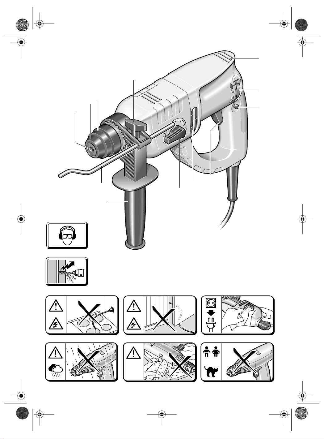
2 Bild
1 Werkzeugaufnahme
2 Staubschutzkappe
3 Entriegelungshülse
4 Spannschraube für Zusatzgriff/Tiefenanschlag
5 Lüftungsschlitze
6 Drehrichtungsumschalter
7 Feststellknopf für Ein-/Ausschalter
8 Ein-/Ausschalter
9 Lüftungsschlitze
10 Umschalter Bohren/Hammerbohren
11 Tiefenanschlag
12 Zusatzgriff
13 Adapter für Schraub-Bits/Bohrfutter
Abgebildetes oder beschriebenes Zubehör muß nicht
zum Lieferumfang gehören.
3 Technische Daten
Pneumatik-Bohrhammer
Aufnahmeleistung550 Watt
Abgabeleistung270 Watt
Halbwellensteuerung
Leerlaufdrehzahl0-1000 1/min
Lastdrehzahl0-750 1/min
Leerlaufschlagzahlmax. 4950 1/min
Lastschlagzahlmax. ca. 4100 1/min
Schlagenergie max. 2,0 J
Rechts-/Linkslauf
Spannhals-ø 43 mm Euro-Norm
Werkzeugaufnahme SDS-Plus
Bohr-Ø max.
Stahl 13 mm
Leichtmetall 16 mm
Holz 30 mm
Hammerbohren in Beton 20 mm
Empfohlener Bohrbereich
Hammerbohren 5-14 mm
Schrauben-Ø max.
Holz 6 mm
Blech 6,3 mm
Eckmaß 33 mm
Gewicht 2,175 kg
Schutzklasse II/
•
•
4 Lärm-/Vibrationsinformation
Messwerte ermittelt entsprechend EN 60 745.
Der A-bewertete Geräuschpegel des Geräts beträgt
typischerweise: Schalldruckpegel 94 dB (A);
Schallleistungspegel 105 dB (A). Messunsicherheit
K= 3 dB
Gehörschutz tragen!
Die bewertete Beschleunigung beträgt typischerweise 8,1 m/s .
2
Page 5

PH 500 - Buch Seite 5 Montag, 17. September 2001 11:54 11
SPEED
Deutsch5
5 Zusatzgriff montieren, Netzkabel
Ziehen Sie vor allen Arbeiten am Gerät den Netzstecker.
Betreiben Sie das Gerät nur mit dem Zusatzgriff 12.
Den Zusatzgriff auf den Spannhals setzen und mit der
Spannschraube festziehen.
Beschädigte Netzkabel dürfen nicht verwendet werden. Sie sind unverzüglich durch eine autorisierte Service-Stelle zu erneuern (schwere Gummischlauchleitung Code-Bezeichnung H 07 RN-F).
6 Inbetriebnahme
Prüfen Sie vor Inbetriebnahme, ob die Netzspannung mit der Angabe auf dem Typenschild des
Gerätes übereinstimmt.
EIN-/AUSSCHALTEN
Den Ein-/Ausschalter 8 drücken bzw. wieder loslassen.
Der Ein-/Ausschalter kann mit dem Feststellknopf 7
arretiert werden. Zum Lösen den Ein-/Ausschalter 8
kurz drücken und loslassen.
BOHREN - HAMMERBOHREN
Zum Bohren den Umschalter 10 auf stellen.
Zum Hammerbohren auf stellen.
Die Umschaltung läßt sich am besten im Stillstand
vornehmen. Nach Betätigung des Ein-/Ausschalters 8
bzw. beim Anlaufen der Maschine schaltet das
Getriebe in die vorgewählte Einstellung.
Hinweise: Linkslauf beim Hammerbohren beschädigt
den Bohrer. Bei Arbeiten mit Diamant-Bohrkronen
und bei Rührarbeiten das Schlagwerk ausschalten.
Verwenden Sie beim Hammerbohren ausschließlich hartmetallbestückte Bohrer mit SDS plusSchaft. Die Verwendung handelsüblicher Steinbohrer
mit zylindrischem Schaft unter Verwendung des
Adapters 13 und eines üblichen Bohrfutters unter Einsatz des pneumatischen Hammerwerkes ist nicht
möglich.
DREHZAHLSTEUERUNG
Mit dem Ein-/Ausschalter 8
können zwei Drehzahlenstufen
gewählt werden.
Zum Anbohren den Ein-/Ausschalter 8 leicht drücken (Anbohrstufe), für volle Bohrleistung den
Schalter 8 ganz drücken.
DREHRICHTUNG UMSCHALTEN
Betätigen Sie den Drehrichtungsumschalter 6 nur im Stillstand!
Greifen Sie den Drehrichtungsumschalter 6 beidseitig.
Rechtslauf: Drehrichtungsumschalter 6 auf „R“
stellen.
Linkslauf: Drehrichtungsumschalter 6 auf „L“
stellen.
Wichtig: Drehrichtungsumschalter 6 jeweils bis zum
Anschlag am Gehäuse durchdrücken, d.h. bis er spürbar einrastet.
Steht der Drehrichtungsumschalter 6 zwischen Pos.
„R“ und „L“, kann die Maschine nicht eingeschaltet
werden.
7 Werkzeug einsetzen/entnehmen
Die Werkzeugaufnahme 1 spannt Bohrwerkzeuge
ohne Werkzeugschlüssel.
WERKZEUG EINSETZEN
Ziehen Sie vor allen Arbeiten am Gerät den Netzstecker.
Reinigen Sie den Werkzeugschaft und fetten Sie ihn
leicht.
Fett
3
Ziehen Sie die Entriegelungshülse 3 zurück. Führen
Sie das Werkzeug drehend in die Werkzeugaufnahme ein, bis es einrastet. Lassen Sie die Entriegelungshülse los. Prüfen Sie das Werkzeug auf festen
Sitz.
Achten Sie darauf, daß die Staubschutzkappe 2 nicht
beschädigt wird.
Beschädigte Staubschutzkappe unbedingt ersetzen!
WERKZEUG ENTNEHMEN
Schieben Sie die Entriegelungshülse 3 nach hinten
und ziehen Sie das Werkzeug heraus.
Page 6
PH 500 - Buch Seite 6 Montag, 17. September 2001 11:54 11
6 Deutsch
8 Bohrfutter (Zubehör)
Für Bohrarbeiten in Metall, Holz und Kunststoff mit
Bohrern mit normalem Schaft, ist ein Bohrfutter
(max.13 mm Spannweite) lieferbar. Das Bohrfutter
wird auf den Adapter (Zubehör) für Schraub-Bits montiert. Es können alle üblichen Bohrfutter mit Innengewinde 1/2" × 20 UNF (Spannweite max.13 mm) verwendet werden.
BOHRFUTTER MONTIEREN
Ziehen Sie vor allen Arbeiten am Gerät den Netzstecker.
Gewinde am Bohrfutter (Zubehör) und am Adapter 13
(Zubehör) reinigen. Schrauben Sie das Bohrfutter auf
den Adapter und ziehen Sie es fest (ca. 30 Nm). Zum
Festziehen den Adapter zum Beispiel in einen
Schraubstock spannen. Im Bohrfutter einen Sechskantschlüssel festspannen und mit diesem das Bohrfutter festziehen. Verriegeln Sie dann den Adapter wie
einen Bohrer in der Werkzeugaufnahme.
9 Für die Praxis
Bohren Sie nicht in verdeckt liegende elektrische Leitungen, Gasund Wasserrohre. Untersuchen
Sie vorher die zu bearbeitenden
Flächen; zum Beispiel mit einem
Metallortungsgerät.
Verwenden Sie für Metall nur einwandfrei geschärfte
Bohrer, für Stein und Beton nur hartmetallbestückte
Gesteinsbohrer.
Passen Sie die Drehzahl immer dem zu bearbeitenden Werkstoff und dem Bohrerdurchmesser an. Für
genaues Arbeiten in Metall und Holz die Maschine in
einen Bohrständer (Zubehör) setzen.
HAMMERBOHREN
Schutzbrille und Gehörschutz
tragen.
Üben Sie keinen zu starken Anpressdruck aus. Die
Leistung wird dadurch nicht erhöht.
Beim Hammerbohren nur mit Schutzbrille, Gehörschutz und Zusatzgriff 12 arbeiten. Prüfen Sie vor
der Inbetriebnahme, ob der Umschalter 10 in Stellung eingerastet ist.
IN FLIESEN BOHREN
Eine Fliese langsam anbohren. Erst wenn die Fliese
durchbohrt ist, auf Hammerbohren umstellen.
SCHRAUBEN
Der Adapter 13 (Zubehör) kann Schraub-Bits aufnehmen. Es können handelsübliche Bits eingesetzt
werden mit dem Sechskantmaß 6,3 mm bzw. 1/4"
(DIN 3126, Form C).
Schraub-Bits werden im Adapter durch einen Federring gehalten. Deswegen nur Bits mit Kerben einsetzen.
10 Rutschkupplung
Klemmt oder hakt das Bohrwerkzeug, löst die Rutschkupplung aus.
Entlasten Sie sofort die Maschine, indem Sie das
Bohrwerkzeug zurückziehen.
Halten Sie die Maschine immer fest mit beiden
Händen und nehmen Sie einen sicheren Stand ein.
11 Wartungsmaßnahmen
Ziehen Sie vor allen Arbeiten am Gerät den Netz-
stecker.
Halten Sie die Lüftungsschlitze stets sauber.
Von außen zugängliche Kunststoffteile regelmäßig
mit einem Tuch ohne Reinigungsmittel abwischen.
Nach starker Beanspruchung über einen längeren
Zeitraum sollte das Gerät zur Inspektion und gründlichen Reinigung einer Kress-Servicestelle zugeführt
werden.
12 Umweltschutz
Werfen Sie Elektrowerkzeuge
nicht in den Hausmüll.
Rohstoffrückgewinnung
statt Müllentsorgung
sollten einer umweltgerechten Wiederverwertung
zugeführt werden.
Diese Anleitung ist aus chlorfrei
Recycling-Papier hergestellt.
Zum sortenreinen Recycling sind Kunststoffteile ge-
kennzeichnet.
Gerät, Zubehör und Verpackung
Änderungen vorbehalten
gefertigtem
Page 7

PH 500 - GB Seite 7 Dienstag, 18. September 2001 11:20 11
English7
Application
The pneumatic drill hammer is universally usable for
hammer drilling and drilling as well as for screwdriving
in wood, metal and plastic.
This pneumatic drill hammer is not suited for
☞
chiselling work (also not with pointed chisels).
1
Before putting the machine into operation, read
through these operating instructions completely and
observe the safety instructions contained therein as
well as those in the enclosed booklet on general
safety instructions for electro-tools.
If the mains cable is damaged while working, pull
the mains plug immediately.
Never work with a damaged mains cable.
Wear protective glasses, hearing protection, pro-
tective gloves and sturdy shoes.
Wear hearing protection. Exposure to noise
can cause hearing loss.
Use the auxiliary handles supplied with the
machine. Loss of control can cause personal
injury.
Do not work with materials containing asbestos.
Do not carry the machine by the cable.
The mains receptacles in the working area must be
protected by a residual current circuit breaker (RC).
For the attachment of identification markings on the
machine, do not drill into the housing. The protective insulation would be shorted. Use stickers.
When the drill unexpectedly jams, the machine
kicks back. Therefore, always take a secure stance
and hold the machine firmly with both hands.
Safety Instructions and
Accident Prevention
3 Technical Data
Pneumatic Drill Hammer
Input power550 Watt
Output power270 Watt
Half-wave control
No-load speed0-1000 RPM
Speed under load0-750 RPM
No-load impact ratemax. 4950 RPM
Load hammer blowsmax. approx. 4100 RPM
Impact energie max. 2.0 J
Right/Left rotation
Clamping collar dia. 43 mm Euro standard
Tool holder SDS-Plus
Drill dia., max.
Steel 13 mm
Light metal 16 mm
Wood 30 mm
Hammer drilling in
conctrete 20 mm
Recommended hammer
drilling range 5-14 mm
Screw dia., max.
Wood 6 mm
Sheet metal 6.3 mm
Corner measure 33 mm
Weight 2.175 kg
Protection class II/
•
•
4 Noise/vibration information
2 Illustration
1 Tool holder
2 Dust protection cap
3 Unlocking collar
4 Clamping screw for auxiliary handle/depth stop
5 Ventilation slots
6 Rotational direction switch
7 Locking button for on/off switch
8 On/Off switchr
9 Ventilation slots
10 Drilling/Impact drilling selector
11 Depth stop
12 Auxiliary handle
13 Adapter for screwdriver bits/drill chuck
Accessories illustrated or described are not always
included as standard delivery items.
Measured values determined according to
EN 60 745.
Typically the A-weighted noise levels of the machine
are: sound pressure level 94 dB (A); sound power level
105 dB (A). Measurement uncertainty
K = 3 dB.
Wear hearing protection!
The typically weighted acceleration is 8,1 m/s
².
Page 8

PH 500 - GB Seite 8 Montag, 17. September 2001 1:20 13
SPEED
8 English
Mounting the Auxiliary Handle,
5
Powersupply Cord
Before any work on the machine itself, pull the
mains plug!
Operate the machine only with the auxiliary handle 12. Place the auxiliary handle on the clamping
collar and tighten with the clamping screw.
Damaged mains cables must not be used. They must
be replaced without delay by an authorised servicing
agent (heavy rubber sheathed code designation
H 07 RN-F).
6 Putting into Operation
Check before putting into operation that the mains
voltage agrees with the voltage specified on the
nameplate of the machine.
SWITCHING ON/OFF
Press or release the on/off switch 8.
The on/off switch can be locked on with the locking
button 7. To release, briefly press and release the on/
off switch 8.
DRILLING - IMPACT DRILLING
For drilling, place the selector 10 in the position.
For impact drilling, set to .
The switch-over can best be performed at a standstill.
Only after the on/off switch 8 is actuated and the
machine starts does the gear box shift to the selected
mode.
Note: Left rotation when impact drilling damages the
drill. Switch off the impact mechanism for diamond
crown drilling or for mixing work.
When hammer drilling, use exclusively drills with
hard metal inserts and SDS-Plus shafts. The use of
commercially available masonry drills with cylindrical
shafts by means of the adapter 13 and the normal drill
chuck in conjunction with the pneumatic impact mechanism is not possible.
SPEED CONTROL
With the On/Off switch 8, two speed
steps can be selected.
For hole starting, press the On/Off
switch 8 lightly (hole starting step).
For full drilling performance, press
in the On/Off switch 8 completely.
ROTATIONAL DIRECTION SWITCHING
Operate the rotational direction
switch 6 only when the machine is
at a standstill!
Take hold of the rotational direction
switch 6 on both sides.
Right rotation: Set the rotational direction switch 6
to “R”.
Left rotation: Set the rotational direction switch 6
to “L”.
Important: Press the rotational direction switch 6 in
each case to the stop on the housing, i. e. until it can
be felt to engage.
If the rotational direction switch 6 is set between the
positions “R” and “L”, the machine cannot be switched
on.
7 Inserting/Removing Tools
The tool holder 1 clamps the drilling tools without
using a tool key.
INSERTING TOOLS
Before any work on the machine itself, pull the
mains plug!
Clean and lightly grease the tool shaft.
Fett
3
Pull back the unlocking collar 3. Insert the tool while
turning into the tool holder until it latches. Release the
unlocking collar. Check whether the tool is firmly
seated.
Take care that the dust protection cap 2 is not damaged.
Replace damaged dust protection caps!
REMOVING TOOLS
Slide the unlocking collar 3 to the rear and pull out the
tool.
Page 9

PH 500 - GB Seite 9 Montag, 17. September 2001 1:20 13
English 9
8 Drill Chuck (Accessory)
For drilling work in metal, wood and plastic with drills
that have normal shafts, a drill chuck (13 mm max.
chuck opening) is available. The drill chuck is
mounted on the adapter (accessory) for screwdriver
bits. All common drill chucks with 1/2" x 20 UNF internal threads (13 mm max. chuck opening) can be
used.
MOUNTING THE CHUCK
Before any work on the machine itself, pull the
mains plug!
Clean the threads of the drill chuck (accessory) and
the adapter 13 (accessory). Screw the drill chuck onto
the adapter and tighten firmly (approx. 30 Nm). Clamp
in a vise for tightening the adapter, for example.
Clamp an Allen key in the drill chuck and use it to
tighten the chuck. Then lock the adapter in the tool
holder the same as a drill.
9 Practical Tips
Do not drill into hidden electrical
lines or gas and water pipes.
Check the area to be worked with
a metal detector, for example,
before starting.
For metal, use only flawless, sharpened drills; for
stone and concrete, only masonry drills with hard
metal inserts.
Always adapt the speed to the material to be worked
and the diameter of the drill. For precision working
with metal and wood, place the machine in a drill
stand (accessory).
HAMMER- DRILLING
Wear protective glasses and
hearing protection.
Do not apply to much pressure. The performance is
not increased in this manner.
For hammer drilling, work only with protective
glasses, hearing protection and the auxiliary handle 12. Check before putting into operation if the
shift knob 10 is latched in the position.
DRILLING IN TILES
Start drilling slowly on the tile. After the tile is drilled
through, switch to impact drilling.
SCREWDRIVING
Screwdriver bits can be inserted into the adapter 13
(accessory). Commercially available bits with a hexagonal dimension of 6.3 mm or 1/4" (DIN 3126,
Form C) can be used.
The screwdriver bits are held in the adapter with a
spring ring. Therefore, use only bits with a notch.
10 Slip Clutch
If the drilling tool become jammed or get caught, the
slip clutch releases.
Remove the load from the machine immediately by
pulling back the drilling tool.
Always hold the machine tightly with both hands and
assume a secure stance.
11 Maintenance Measures
Before any work on the machine itself, pull the
mains plug!
Always keep the ventilation slots clean.
Wipe off the accessible plastic parts regularly with a
cloth without cleaning agent.
After heavy use over a long period, the machine
should be taken to a Kress service location for an
inspection and thorough cleaning.
12 Environmental Protection
Do not dispose of electric tools
together with household waste
material!
Recycle raw materials instead of dis-posing as waste.
The machine, accessories and packa-
ging should be sorted for environ-
mental friendly recycling.
These instructions are printed on
manufactured without chlorine.
The plastic components are labelled for categorised
recycling.
Subject to change without notice
recycled paper
Page 10

PH 500 - Buch Seite 10 Montag, 17. September 2001 11:54 11
10 Français
Utilisation
Le perforateur pneumatique est d’un usage universel, par
exemple pour le perçage, le perçage en frappe ainsi que le
vissage dans le bois, le métal et les matières plastiques.
Ce marteau perforateur pneumatique n'est pas
☞
approprié pour des travaux de burinage (même
avec un burin pointu).
1
Lire attentivement l’ensemble de la notice d’utilisation avant
de mettre la machine en service. Suivre les consignes de
sécurité spécifiques figurant dans la présente notice ainsi
que les consignes relatives à la sécurité en matière
d’outillage électro-portatif, définies dans le feuillet joint.
Si le cordon d’alimentation est endommagé pendant
un travail, extraire immédiatement la fiche du cordon
d’alimentation hors de la prise électrique.
Ne jamais travailler avec un cordon d’alimentation
endommagé.
Porter une paire de lunettes de sécurité, une protection acoustique, une paire de gants de travail ainsi
qu’une paire de solides chaussures.
Portez une protection acoustique. Une forte ex-
position au bruit peut provoquer une perte d'audition.
Utilisez les poignées supplémentaires fournies
avec l'appareil. Le fait de perdre le contrôle
de l'appareil peut entraîner des blessures.
Ne pas travailler les matériaux contenant de l’amiante.
Ne jamais porter l’appareil par son cordon d’alimenta-
tion.
Les prises électriques situées en extérieur doivent être
protégées par un disjoncteur à courant de défaut.
Ne jamais percer le carter de cet appareil dans le but
de le marquer ou de l’identifier. Cela court-circuiterait
le dispositif d’isolation électrique. Utiliser plutôt un
autocollant.
Lorsque le foret de la perceuse se coince sans préavis
dans un matériau, la machine réagit brutalement. Il
convient donc de toujours adopter une position de travail sûre et stable et d’utiliser ses deux mains pour
maintenir fermement la machine en position.
Consignes de sécurité et
prévention des accidents
2 Figure
1 Fixation de l’outil
2 Capuchon anti-poussières
3 Bague de verrouillage
4 Vis de serrage pour poignée supplémentaire / butée
de profondeur
5 Ouïes de refroidissement
6 Commutateur du sens de rotation
7 Cran d’arrêt de l’interrupteur Arrêt/Marche
8 Interrupteur Arrêt/Marche
9 Ouïes de refroidissement
10 Commutateur perçage simple / avec percussion
11 Butée de profondeur
12 Poignée supplémentaire
13 Adaptateur pour mandrins et embouts de tournevis
Les accessoires reproduits et décrits dans la notice
d’instruction ne sont pas forcément compris dans les
fournitures.
3 Caractéristiques techniques
Perforateur pneumatique
Puissance absorbée550 Watt
Puissance débitée270 Watt
Electronique à demi-onde
Vitesse à vide0-1000 1/min
Régime en charge0-750 1/min
Fréquence de frappe à videmax. 4950 1/min
Fréquence de frappes en chargemax. env. 4100 1/min
Travail per coup max. 2,0 J
Rotation droite et gauche
ø du collet de broche 43 mm (norme eur.)
Fixation de l’outil SDS-Plus
Ø max. des foret
Dans l’acier 13 mm
Dans les alliages légers 16 mm
Dans le bois 30 mm
Travaux de perçage dans le
béton avec le marteau
perforateur 20 mm
Diamètre de perçage
recommandé pour le marteau
perforateur 5-14 mm
Ø max. des vis
Dans le bois 6 mm
Dans la tôle 6,3 mm
Mesure angulaire 33 mm
Poids 2,175 kg
Classe de protection II/
•
•
4 Bruits et vibrations
Valeurs de mesure obtenues conformément à la
norme européenne EN 60 745.
Les mesures réelles (A) des niveaux sonores de
l'appareils sont: niveau de pression acoustique
94 dB (A); niveau d'intensité acoustique 105 dB (A).
Incertitude de mesurage K = 3 dB.
Toujours porter une protection acoustique!
L’accélération réelle mesurée est de 8,1 m/s2.
Page 11

PH 500 - Buch Seite 11 Montag, 17. September 2001 11:54 11
SPEED
Français 11
Assemblage de la poignée
5
supplémentaire, cordon
Toujours extraire la fiche du cordon d’alimentation
modulaire hors de la prise électrique avant d’entreprendre une quelconque intervention sur l’appareil luimême.
Cet appareil ne doit être utilisé qu’avec la poignée supplémentaire 12. Monter la poignée supplémentaire sur le
collet de broche. Visser et bloquer la vis.
Des câbles de secteur endommagées ne doivent pas être
utilisés. Ils doivent être immédiatement remplacés par
une entreprise compétente les gaines en caoutchouc
lourdes (code de référence H 07 RN-F).
6 Mise en service
Avant de mettre l’appareil en service, toujours s’assurer au préalable que la tension fournie par le secteur
coïncide bien avec celle qui est indiquée sur la plaquette signalétique de l’appareil.
MISE EN MARCHE / ARRET
Enfoncer, respectivement: relâcher, l’interrupteur
Marche/Arrêt 8.
L’interrupteur Marche/Arrêt peut être verrouillé en position "Marche" via le cran d’arrêt 7. Pour désactiver ce verrouillage, enfoncer brièvement puis relâcher l’interrupteur
Marche/Arrêt 8.
PERÇAGE - PERÇAGE AVEC PERCUSSION
Pour effectuer un perçage sans percussion, mettre le
commutateur 10 sur la position .
Pour effectuer un perçage avec percussion, mettre le
commutateur sur la position .
Le mieux est de commuter à l’arrêt total de la machine.
Après avoir actionné l’interrupteur Marche/Arrêt 8 ou lors
du démarrage de la machine, l’engrenage s’enclenche
dans la position sélectionnée préalablement.
Remarque: Lorsqu’un foret est monté sur la broche, le
fait d’utiliser la rotation à gauche endommage le foret.
Lors de travaux avec des couronnes diamantées et lors
de travaux avec un agitateur, mettre le mécanisme de
frappe hors fonctionnement.
Pour les travaux de perçage en frappe, utiliser exclusivement des forets carbure avec queue SDS-Plus. Il
n’est pas possible d’utiliser des forets à pierre à queue
cylindrique, comme on les trouve dans le commerce,
avec l’adaptateur 13 et le mandrin de perçage habituel en
travaillant avec le mécanisme de frappe pneumatique.
RÉGLAGE DE LA VITESSE DE ROTATION
A l'aide de l'interrupteur Marche/
Arrêt 8, il est possible de choisir
entre deux vitesses de rotation
différentes.
Pour démarrer le perçage, appuyer
légèrement sur l'interrupteur Marche/
Arrêt 8 (vitesse de rotation pour centrage). Pour disposer
de toute la puissance de la perceuse, appuyer à fond sur
l'interrupteur Marche/Arrêt 8.
COMMUTATION DU SENS DE ROTATION
Le commutateur de sens de rotation 6
ne doit être actionné que lorsque la
machine est à l’arrêt complet!
Saisir le commutateur de sens de
rotation 6.
Rotation à droite: mettre le commutateur de sens de
rotation 6 sur la position „R“.
Rotation à gauche: mettre le commutateur de sens de
rotation 6 sur la position „L“.
Important: Appuyer chaque fois à fond le commutateur
de sens de rotation 6, c‘est-à-dire veiller à ce qu‘il s‘encliquette de façon perceptible.
Lorsque le commutateur de sens de rotation 6 a été mis
sur une position intermédiaire entre „R“ (rotation à droite)
et „L“ (rotation à gauche), l’appareil ne se met pas en
marche.
7 Mise en place / Retrait de l’outil
C’est le dispositif de fixation de l’outil 1 qui effectue le serrage de l’outil de perçage sans qu’une clé de mandrin soit
nécessaire.
MISE EN PLACE DE L’OUTIL
Toujours extraire la fiche du cordon d’alimentation
modulaire hors de la prise électrique avant d’entreprendre une quelconque intervention sur l’appareil luimême.
Nettoyer puis graisser légèrement la queue de l’outil.
Fett
3
Repousser la bague de verrouillage 3 vers l’arrière. Introduire l’outil dans la fixation tout en imprimant à l’outil un
mouvement de rotation selon son axe principal, jusqu’à
ce qu’il enclenche. Relâcher la bague de verrouillage 3.
Contrôler enfin que l’outil est bien en place et parfaitement maintenu.
Veiller à ne pas endommager le capuchon anti-poussières 2.
Page 12

PH 500 - Buch Seite 12 Montag, 17. September 2001 11:54 11
12 Français
Remplacer sans délai tout capuchon anti-poussières
détérioré!
RETRAIT DE L’OUTIL
Repousser la bague de verrouillage 3 vers l’arrière.
Extraire l’outil hors de la fixation.
8 Mandrin (accessoire)
Pour réaliser des travaux de perçage dans le métal, le
bois et les matières plastiques au moyen d’un foret à
queue cylindrique, l’utilisateur peut faire appel à un mandrin (de 13 mm d’ouverture maximale), livrable en tant
qu’accessoire. Ce mandrin se monte sur l’adaptateur
(accessoire) permettant d’utiliser le programme
d’embouts de tournevis. L’appareil est compatible avec
n’importe quel mandrin conventionnel doté d’un filetage
intérieur 1/2" x 20 UNF (de 13 mm d’ouverture maximale).
MONTAGE D’UN MANDRIN
Toujours extraire la fiche du cordon d’alimentation
modulaire hors de la prise électrique avant d’entreprendre une quelconque intervention sur l’appareil luimême.
Nettoyer le filetage du mandrin (accessoire) ainsi que
celui de l’adaptateur 13 (accessoire). Visser le mandrin
de perçage sur l’adaptateur et le serrer à fond (30 Nm
env.). Pour ce faire, serrer l’adaptateur par exemple dans
un étau. Serrer une clé mâle pour vis à six pans creux et
avec celle-ci serrer le mandrin de perçage. Puis verrouiller l’adaptateur dans la fixation de l’outil comme si
c’était un foret.
9 Conseils pratiques
Ne pas percer de trous à travers des
gaines électriques ou des conduites
d’eau ou de gaz dissimulées. Avant
de percer, procéder toujours à un
examen de la paroi considérée. Si
nécessaire, faire appel à un détecteur de métal.
Pour percer dans les métaux, il convient de toujours utiliser un foret parfaitement affûté et en excellent état. Pour
percer la pierre ou le béton, utiliser des forets à mise au
carbure.
Ajuster toujours la vitesse de rotation du foret au matériau
à travailler d’une part et au diamètre du foret mis en
oeuvre d’autre part. Pour travailler de manière encore
plus précise dans les métaux ou dans le bois, faire appel
à un support de preçage (accessoire).
PERÇAGE AVEC PERCUSSION
Porter des lunettes de sécurité
ainsi qu’une protection acoustique.
Ne pas exercer de pression exagérée. Cela ne contribue
pas à améliorer les performances de la machine.
Lors du perçage en frappe, ne travailler qu'avec des
lunettes de protection, une protection acoustique et la
poignée supplémentaire 12.Avant la mise en service,
contrôler si le commutateur 10 est bien encliqueté
dans la position .
PERÇAGE DANS DU CARRELAGE
Le perçage d’un carreau de faïence doit s’effectuer à
petite vitesse. N’activer le mécanisme de frappe qu’après
avoir complètement traversé le carreau de faïence.
VISSAGE
L’adaptateur 13 (accessoire) permet d’utiliser les
embouts de tournevis. Il est compatible avec les embouts
de tournevis du commerce dotés d’une queue six pans de
6,3 mm (1/4", DIN 3126, profil C).
Les embouts de tournevis sont maintenus dans l’adaptateur par un ressort. Il convient donc de ne travailler
qu’avec des embouts dotés d’une rainure latérale.
10 Accouplement à glissement
Dès que l’outil de perçage se coince ou qu’il s’accroche,
l’accouplement à glissement se déclenche.
Décharger immédiatement la machine en tirant l’outil de
perçage vers l’arrière.
Maintenir toujours la machine des deux mains et prendre
une position stable et bien en équilibre.
11 Interventions de maintenance
Toujours extraire la fiche du cordon d’alimentation
modulaire hors de la prise électrique avant d’entreprendre une quelconque intervention sur l’appareil luimême.
Les ouïes de refroidissement de la machine doivent rester
propres.
Essuyer régulièrement les pièces en matière plastique
accessibles de l’extérieur avec un chiffon humide mais
non imbibé de produit de nettoyage.
Après avoir exploité la machine de manière intensive pendant une longue période, la confier à un centre de service
agréé Kress afin qu’elle soit inspectée sérieusement et
complètement nettoyée.
12 Protection de l’environnement
Ne pas jeter les appareils électriques
dans les ordures ménagères !
Récupération des matières premières
plutôt qu'élimination des déchets
Les appareils, comme d'ailleurs leurs
accessoires et emballages, doivent
recyclage appropriée.
Ce manuel d'instructions a été fabriqué à partir d'un
papier recyclé blanchi sans chlore.
Nos pièces plastiques ont été marquées en vue d'un
recyclage sélectif des différents matériaux.
pouvoir suivre chacun une voie de
Sous réserves de modifications techniques
Page 13

PH 500 - Buch Seite 16 Montag, 17. September 2001 11:54 11
13 Italiano
Applicazione
Il martello perforatore pneumatico è applicabile universalmente per forature, per forature a martello, per avvitare
viti nel legno, nel metallo ed in materiali sintetici.
Questo martello perforatore pneumatico non è
☞
indicato per lavori di scalpellatura (anche utilizzando uno scalpello a punta).
1
Prima di mettere la macchina in esercizio, leggere completamente le Istruzioni per l’uso, rispettare le indicazioni
di sicurezza contenute nella presente Istruzione nonchè
le indicazioni generali di sicurezza per macchine elettriche riportate nell’opuscolo allegato.
Qualora durante l’operazione di lavoro venisse danneggiato il cavo di rete, estrarre immediatamente la
spina dalla presa della corrente.
Mai lavorare con un cavo di rete danneggiato.
Portare gli occhiali, la cuffia ed i guanti di protezione,
nonchè scarpe di sicurezza.
Indossare una protezione acustica. L'effetto del
rumore può causare la perdita dell'udito.
Utilizzare le impugnature supplementari fornite
in dotazione con la macchina. La perdita di
controllo della macchina può provocare incidenti
Non lavorare su materiale contenente amianto.
Non trasportare la macchina tenendola per il cavo.
Le prese in ambienti esterni devono essere assicurate
tramite un interruttore di sicurezza per correnti di
guasto (FI).
Non è permesso perforare la carcassa della macchina
al fine di volerla contrassegnare. L’isolazione di protezione viene ponticellata. Utilizzare targhette autoincollanti.
Se la punta dovesse bloccarsi inaspettativamente, la
macchina reagisce con contraccolpi. Mantenere
perciò sempre una distanza di sicurezza e tenere bene
la macchina con entrambe le mani.
Indicazioni di sicurezza e
misure antinfortunistiche
.
2 Figura
1 Attacco utensili
2 Protezione antipolvere
3 Boccola di sbloccaggio
4 Vite di serraggio per impugnatura supplementare/
battuta profondità
5 Feritoia di ventilazione
6 Commutatore per la reversibilità
7 Pulsante di bloccaggio per interruttore di inserimento/
disinserimento
8 Interruttore di inserimento/disinserimento
9 Feritoia di ventilazione
10 Selettore Foratura / Foratura a martello
11 Battuta profondità
12 Impugnatura supplementare
13 Adattatore per bit cacciaviti - mandrino portapunta
Accessori illustrati o descritti non fanno necessariamente parte del volume di consegna.
3 Dati tecnici
Martello perforatore
pneumatico
Potenza assorbita550 Watt
Potenza resa270 Watt
Comando a semionde
Num. di giri a vuoto0-1000 1/min
Numero di giri sotto carico0-750 1/min
Numero di percussioni a vuotomass. 4950 1/min
Numero di colpi a pieno caricomass. ca. 4100 1/min
Potenza della percussioni mass. 2,0 J
Funzionamento reversibile
Diametro collare ø 43 mm Norma Euro
Attacco utensili SDS-Plus
Diametro punta, mass.
Acciaio 13 mm
Metallo leggero 16 mm
Legno 30 mm
Foratura a martello nel
calcestruzzo 20 mm
Campo di foratura consigliato
per foratura a martello 5-14 mm
Diametro viti, mass.
Legno 6 mm
Lamiera 6,3 mm
Misura angolare33 mm
Peso 2,175 kg
Classe di protezioneII/
Informazioni sulla rumorosità e
4
sulla vibrazione
Valori misurati conformemente alla norma EN 60 745.
La misurazione A del livello di pressione acustica della
macchina è solitamente di pressione acustica 94 dB (A);
livello della potenza sonora 105 dB (A).
Incertezza della misura K = 3 dB.
Usare auricolari di protezione!
L'accelerazione misurata raggiunge di solito il valore
di 8,1 m/s
².
•
•
Page 14

PH 500 - Buch Seite 17 Montag, 17. September 2001 11:54 11
SPEED
Italiano14
Montaggio dell’impugnatura
5
supplementare, cavo
Prima di ogni intervento alla macchina, estrarre la
spina dalla prese di rete.
Utilizzare la macchina con l’impugnatura supplementare 12. Mettere l’impugnatura supplementare sul diametro collare ed avvitare forte con la vite di serraggio.
Non utilizzare cavi d‘alimentazione danneggiati. Essi
vanno sostituiti immediatamente a cura di un centro di
assistenza autorizzato (pesanti fili isolati in gomma
codice commerciale H 07 RN-F).
6 Messa in esercizio
Prima della messa in esercizio, controllare che la tensione di rete corrisponda ai valori indicati sulla targhetta di costruzione della macchina.
INSERIMENTO-DISINSERIMENTO
Premere oppure lasciare l’interruttore di inserimento/
disinserimento 8.
L’interruttore di inserimento/disinserimento può essere
bloccato con il pulsante di fissaggio 7. Per sbloccare,
premere brevemente l’interruttore di inserimento/disinserimento 8 e lasciarlo.
FORATURA - FORATURA A MARTELLO
Per forare, mettere il selettore 10 in posizione .
Per foratura a martello metterlo in posizione .
Il modo più semplice di eseguire la commutazione è
quando la macchina è ferma. Azionando l’interruttore di
inserimento-disinserimento 8 opp. all’avvio della macchina, la trasmissione passa all’impostazione preselezionata.
Indicazioni: La rotazione sinistrorsa nel corso di foratura
a martello danneggia la punta. Lavorando con una corona
a forare diamantata ed in caso di lavori di miscelazione è
indispensabile disinserire il sistema battente.
In caso di foratura a martello è indispensabile utilizzare esclusivamente punte con applicazioni di placchette di metallo duro e con un gambo SDS-plus. Non
è possibile utilizzare punte per pietra comunemente in
commercio con gambo cilindrico ed adattatore 13 né è
possibile utilizzare un comune mandrino portapunta in
caso di impiego del martello pneumatico.
CONTROLLO DI VELOCITÀ
Con l'interruttore acceso/spento 8
si possono selezionare due livelli di
velocità.
Per iniziare a perforare premere
leggermentel'interruttore
perforazioneiniziale); per avere la massima potenza
di perforazionepremere del tutto l'interruttore 8.
acceso/spento 8 (livello di
INVERSIONE DELLA DIREZIONE DI MARCIA
Azionare il commutatore per la reversibilità 6 solo a macchina ferma!
Afferrare il commutatore per la reversibilità 6 per entrambi i lati.
Rotazione destrorsa: mettere il commutatore per
la reversibilità 6 nella posizione „R“.
Rotazione sinistrorsa: mettere il commutatore per
la reversibilità 6 nella posizione „L“.
Importante: Premere rispettivamente il commutatore per
la reversibilità 6 fino alla battuta nella carcassa, cioè, fino
a percepirne l‘incastro.
Se il commutatore per la reversibilità 6 si trova tra la posizione „R“ e „L“, la macchina non può essere messa in
esercizio.
7 Inserire ed estrarre gli utensili
L’attacco utensili 1 blocca le punte senza la necessità di
ricorrere ad altri utensilil.
INSERIRE L’UTENSILE
Prima di ogni intervento alla macchina, estrarre la
spina dalla prese di rete.
Pulire il gambo dell’utensile e lubrificarlo leggermente.
Fett
3
Estrarre all’indietro la boccola di sbloccaggio 3. Ruotandolo, inserire l’utensile nell’attacco utensili fino a quando
fa presa. Lasciare il mandrino di serraggio. Controllare
che l’utensile sia ben fisso.
Fare attenzione a non danneggiare la protezione antipolvere 2.
Se la protezione antipolvere è danneggiata, è estremamente importante sostituirla!
ESTRARRE L’UTENSILE
Spingere all’indietro la boccola di sbloccaggio 3 ed
estrarre l’utensile.
Page 15

PH 500 - Buch Seite 18 Montag, 17. September 2001 11:54 11
15 Italiano
8 Mandrino portapunta (Accessorio)
Per lavori di foratura nel metallo, nel legno e in materiali
artificiali tramite punte con un gambo normale, è fornibile
un mandrino portapunta (mass. 13 mm apertura). Il mandrino viene montato sull’adattatore (accessorio) per bit
cacciaviti. è possibile utilizzare tutti i mandrini comunemente reperibili sul mercato che abbiano una madrevite
1/2" × 20 UNF (apertura mass. 13 mm).
MONTARE IL MANDRINO PORTAPUNTA
Prima di ogni intervento alla macchina, estrarre la
spina dalla prese di rete.
Pulire la filettatura al mandrino portapunta (accessorio)
ed all’adattatore 13 (accessorio). Avvitare il mandrino
portapunta all’adattatore e stringere forte (ca. 30 Nm).
Per poter avvitare bene, fissare il mandrino p.es. in una
morsa. Applicare una chiave a brugola in posizione nel
mandrino portapunta ed avvitare forte il mandrino. Bloccare poi l’adattatore nell’attacco utensili come si trattasse
di una normale punta.
9 Consigli pratici
Non forare linee elettriche, nonchè
tubazioni di gas e di acqua posate in
maniera non visibile. Prima di cominciare con l’operazione di foratura,
controllare le superfici utilizzando
p.e. un rilevatore di metalli.
Per forare nel metallo, utilizzare esclusivamente punte
perfettamente in ordine e bene affilate; per forare nella
pietra e nel calcestruzzo, utilizzare esclusivamente punte
per pietra con applicazioni di placchette di metallo duro.
Regolare il numero di giri sempre in base al tipo di materiale in lavorazione ed in base al diametro della punta. Per
eseguire lavori di precisione nel metallo e nel legno, fissare la macchina in un montante per foratura (accessorio).
FORATURA A MARTELLO
Portare occhiali e cuffie di di protezione.
Non esercitare una pressione troppo forte: non è così che
si raggiunge una prestazione maggiore.
In caso di foratura a martello, operare soltanto utilizzando sempre occhiali di protezione, cuffie di protezione e l’impugnatura supplementare 12. Prima di
mettere in esercizio la macchina, controllare se il selettore 10 si trova nella posizione .
FORARE LE PIASTRELLE
Preforare delicatamente la piastrella ed inserire la foratura a martello solo dopo aver perforato completamente la
piastrella.
AVVITARE
L’adattatore 13 (accessorio) può alloggiare bit cacciaviti.
Possono essere utilizzati bit cacciaviti comunemente
reperibili sul mercato e che abbiano un dado esagonale
da 6,3 mm opp. 1/4" (DIN 3126, Forma C).
I bit cacciaviti vengono tenuti nell’adattatore tramite una
rondella. Per questo motivo, utilizzare soltanto bit che
abbiano apposite tacche.
10 Frizione di sicurezza
Se l’utensile di foratura si blocca oppure resta incastrato,
scatta la frizione di sicurezza.
Liberare immediatamente la macchina dal carico tirando
indietro la punta utensile.
Durante le operazioni di lavoro, tenere la macchina
sempre con entrambe le mani e provvedere ad una sicura
posizione di lavoro.
11 Disposizioni di manutenzione
Prima di ogni intervento alla macchina, estrarre la
spina dalla prese di rete.
Mantenere sempre pulite le feritoie di ventilazione.
Pulire regolarmente con uno straccio e senza detergenti,
parti in materiale artificiale che siano accessibili
dall’esterno.
Dopo un periodo abbastanza lungo in cui la macchina sia
stata soggetta a condizioni operative estreme, sarà
necessario affidare la macchina ad un Centro di servizio
Kress perchè venga eseguita una ispezione ed una minuziosa pulizia.
12 Misure ecologiche
Non gettare le apparecchiature
elettriche tra i rifiuti domestici.
Recupero di materie prime, piuttosto
che smaltimento di rifiuti
Macchina, accessori ed imballaggio
dovrebbero essere inviati ad una
Queste istruzioni sono stampate su
riutilizzazione ecologica.
I componenti in plastica sono contrassegnati
per il riciclaggio selezionato.
Con riserva di modifiche
carta riciclata
sbiancata senza cloro.
Page 16

EN 60 745-2-6, EN 55014-1, EN55014-2, EN61000-3-2, EN61000-3-3
89/336/EWG, 98/37/EG
KRESS-elektrik GmbH & Co. KG, D-72406 Bisingen
Bisingen, im September 2005
Klemens Müller
Leitung Produktoptimierung
Manager Current Product
Page 17

KRESS•OSW 09/01•Garantie PH 500 •page 38
D
Garantie
1. Dieses Elektrowerkzeug wurde mit hoher Präzision gefertigt und
unterliegt strengen werkseitigen Qualitätskontrollen.
2. Daher garantieren wir die kostenlose Beseitigung von Fabrikationsoder Materialfehlern, die innerhalb von 24 Monaten ab Verkaufsdatum an den Endverbraucher auftreten. Wir behalten uns vor, defekte Teile auszubessern oder durch neue zu ersetzen. Ausgetauschte Teile gehen in unser Eigentum über.
3. Unsachgemäße Verwendung oder Behandlung sowie die Öffnung
des Gerätes durch nicht autorisierte Reparaturstellen führen zum
Erlöschen der Garantie. Dem Verschleiß unterworfene Teile sind
von Garantieleistungen ausgeschlossen.
4. Garantieansprüche können nur bei unverzüglicher Meldung von
Mängeln (auch bei Transportschäden) anerkannt werden. Durch
Ausführung von Garantieleistungen wird die Garantiezeit nicht verlängert.
5. Bei Störungen bitte Gerät mit ausgefüllter Garantiekarte und kurzer
Mängelbeschreibung an uns oder die zuständige Servicestelle einsenden. Kaufbeleg beifügen.
6. Durch die von uns übernommenen Garantie-Verpflichtungen werden alle weitergehenden Ansprüche des Käufers – insbesondere
das Recht auf Wandelung, Minderung oder Geltendmachung von
Schadenersatzansprüchen – ausgeschlossen.
7. Dem Käufer steht jedoch nach seiner Wahl das Recht auf Minderung (Herabsetzung des Kaufpreises) oder Wandelung (Rückgängigmachung des Kaufvertrages) zu, falls es uns nicht gelingt, evtl.
auftretende Mängel innerhalb einer angemessenen Frist zu beseitigen.
8. Nicht ausgeschlossen sind die Schadensersatzansprüche nach
den §§ 463, 480 Abs. 2,635 BGB wegen Fehlens zugesicherter Eigenschaften.
9. Die Bestimmungen nach Punkt 7 und 8 gelten nur für den Bereich
der Bundesrepublik Deutschland.
GB
Guarantee
1. This electro-tool was manufactured with high precision and subjected to rigorous factory quality controls.
2. Therefore, we guarantee the cost-free correction of fabrication or
material defects that occur within 24 months of the date of purchase by the end user. We reserve the right to repair defective
parts or replace them with new parts. Replaced parts become our
property.
3. Improper use or handling as well as opening of the machine by unauthorised repair agencies voids the guarantee. Parts subject to
wear are excluded from the guarantee.
4. The guarantee may only be enforced when defects are reported
without undue delay (including shipping damage). Guarantee implementation does not extend the guarantee period.
5. If the tool is defective, please complete the guarantee card and return the unit, guarantee card and a brief description of the problem
to the responsible service location. Please enclose your sales receipt.
6. The guarantee obligations assumed by us shall exclude any further
claims on the part of the buyer, in particular the right to recission of
a sale, reduction and the assertion of damage claims.
7. However, the buyer shall have the right to either a reduction (in the
purchase price) or the recission of the sale (cancellation of the
sales agreement) should we fail to eliminate any defects within a
reasonable period of time.
8. Damage claims in accordance with §§ 463, 480 Paragraph 2,635
BGB due to absence of guaranteed quality shall not be not excluded.
9. The provisions defined in Items 7 and 8 only apply to the Federal
Republic of Germany.
F
Garantie
1. Cet outillage électroportatif a été construit de manière très précise
et a fait, en usine, l’objet de contrôles de qualité très stricts.
2. Cela nous permet d’assurer une réparation gratuite des défauts de
fabrication ou de matériau susceptibles d'être découvertes dans les
24 mois chez l’utilisateur à dater de la date d'achat. Nous nous réservons le droit soit de modifier les pièces défectueuses, soit de
les échanger contre des neuves. Les pièces échangées deviennent alors immédiatement notre propriété.
3. Toute utilisation inadaptée, tout traitement inapproprié, toute ouverture de l’outillage effectuée par un personnel ou un service non habilité à le faire entraîne automatiquement l’extinction de toute revendication relative à cette garantie. Les pièces d’usure sont
expressément exclues de cette garantie.
4. Les revendications de garantie ne pourront être prises en compte
qu’en cas de déclaration immédiate des défauts (avaries dues au
transport y comprises). L’exécution des prestations de garantie ne
donne pas droit à une prolongation de la période de validité de la
garantie.
5. En cas de dysfonctionnement, veuillez expédier l’appareil avec sa
carte de garantie dûment complétée et une brève description des
défauts à notre adresse ou à la station de service après-vente
concernée. Prière de joindre la facture.
6. Une prise en charge par nos soins dans le cadre de la garantie, exclut tout autre recours de la part de l’acheteur, en particulier le droit
de rétraction, de réduction ou de revendication de dommagesintérêts.
7. Cependant, il conserve son droit de rétraction (annulation du
contrat de vente) ou de réduction (abaissement du prix d'achat),
selon ses convenances, si nous ne sommes pas en mesure d'éliminer d’éventuels défauts dans un délai convenable.
8. Ne sont pas exclues, les revendications de dommages-intérêts
selon §§ 463, 480 Al. 2,635 du Code Civil allemand, relatives à
l’absence de propriétés garanties.
9. Les dispositions 7 et 8 ne sont valables que pour l’Allemagne.
I
Garanzia
1. Il presente elettroutensile è stato realizzato secondo criteri produttità da parte della casa costruttrice.
2. Per questo motivo siamo in grado di garantire l’eliminazione gratuita
di difetti costruttivi o di materiale difettoso che dovessero essere riscontrati entro 24 mesi dalla data di vendita all’utente finale. Ci riserviamo il diritto di riparare oppure sostituire le parti difettose. Le
parti sostituite tornano ad essere di proprietà della casa costruttrice.
3. Si perde il diritto di garanzia in caso che la macchina venga impiegata oppure trattata in maniera impropria e, cosippure, se la macchina viene aperta da un Centro Servizio non autorizzato. Le parti
soggette ad usura non sono comprese nella garanzia.
4. La garanzia può essere riconosciuta solo in caso di immediata segalazione del difetto (anche per danni di trasporto). La durata della garanzia non viene prolungata della durata dell'eventuale riparazione.
5. In caso di disturbi preghiamo di spedire l’apparecchio alla fabbrica
o ad un Centro Assistenza autorizzato, insieme alla scheda di garanzia compilata e una breve descrizione del difetto.
6. Gli obblighi di garanzia da noi assunti escludono completamete ulteriori pretese – in particolare il diritto di convertibilità, riduzione del
prezzo o risarcimento danni.
7. L’acquirente può comunque a propria scelta avvalersi del diritto di
riduzione (diminuzione del prezzo d’acquisto) oppure di convertibilità (annullamento del contratto di vendita), nel caso in cui
l’azienda non fosse in grado di eliminare il difetto eventualmente insorto entro un intervallo di tempo ragionevole.
8. Non sono esclusi i diritti al risarcimento danni per i casi contemplati
dal §§ 463, 480 par. 2,635 BGB, riguardanti la mancanza di caratteristiche assicurate.
9. Le disposizioni citate nei punti 7 e 8 sono valide solo per il territorio
della Repubblica Federale Tedesca.
Page 18

Service-Anschriften / After sales service / Service après-vente
Bundesrepublik Deutschland:
KRESS-elektrik GmbH & Co. KG– Elektromotorenfabrik – Abt. Kundendienst/Werk 2
Hechinger Strasse 48, D-72406 Bisingen/Zollernalbkreis,
Telefon +49-(0)74 76-8 74 50 – Telefax +49-(0)74 76-8 73 75
e-mail: tkd@kress-elektrik.de
Serie No.:
Serial No.:
No. de série :
Fabrikations-Nr.:
Manufacturing No.:
Fabrication No. :
Bitte sofort ausfüllen und aufbewahren.
Please fill in immediately and keep in safe place.
Veuillez remplir aussitôt et conserver.
Garantie-Karte
Warranty card
Bon de Garantie
Käufer / Purchaser/ Acheteur :
Kaufdatum:
Date purchased:
Date d'achat :
Verkauft durch / Dealer’s name /Vendeur :
Typ:
Type:
Type :
HM 550
Rueckseite04_03.qxd 02.04.2003 17:25 Uhr Seite 1
Schweiz
CEKA Elektrowerkzeuge AG + Co. KG
Industriestraße 2
CH-9630 Wattwil
Telefon: +41 (0)71 - 987 40 40
E-mail: info@ceka.ch
Belgie/Belgique, Nederland
Present Handel bvba/sprl
Industriezone "Wolfstee"
Toekomstlaan 6
B-2200 Herentals
Téléphone: +32 - (0)14 - 25 74 74
E-mail: info@present.be
France
S.A.R.L. Induba
4 Rue du Viaduc - B.P. 87
F-01130 Les Neyrolles
Téléphone: +33 (0)4 - 74 75 01 33
E-mail: induba@online.fr
Sverige
AB Novum
Mörsaregatan 8
S-25466 Helsingborg
Phone: +46 (0)42 - 15 10 30 Telefax:
E-mail: mail@abnovum.se
Norge
Ifö Electric AS
P.O.B. 336 Alnabru
Brobekkveien 115 B
N-0614 Oslo
Phone: +47 - 23 - 37 81 10
E-mail: info@ifoelectric.no
Hellas
D. Nikolaou & Co Ltd.
Leonidoy 6
GR-17343 Athens
Phone: +30 - 1 - 975 37 57
E-mail: gnikolaou@yahoo.com
Espana
Apolo fijaciones y herramientas s.l.
Garrotxa Naves 10-22
Polig. Ind. Pla. de la Bruguera
E-08211 Castellar del Vallès (Barcelona)
Telefono: +34 - 93 - 747 33 35
E-mail: fijaciones@apolo.es
Telefax: +41 (0)71 - 987 40 41
–
Telefax: +32 - (0)14 - 25 74 75
–
Téléfax: +33 (0)4 - 74 75 23 62
–
–
Talefax: +47 - 23 - 37 81 20
–
Telefax: +30 - 1 - 973 74 23
–
Telefax: +34 - 93 - 747 33 37
–
+46 (0)42 - 16 16 66
Österreich
Bamberger ElektrotechnikMaschinenbau
Braunauer Str.1 C
A-5230 Mattighofen
Telefon: +43 (0)77 42 - 23 63 – Telefax: +43 (0)77 42 - 45 10
E-mail: office@bamberger.at
Italia
Hodara Utensili S.p.A.
Viale Lombardia, 16
I-20090 Buccinasco (Milano)
Telefon: +39 - 02 - 48 84 25 97
E-mail: info@hodara.it
Danmark
Ryttergaard Vaerktoj A/S
Postbox 118, Rodovrevej 151
DK-2610 Rodovre
Phone: +45 - 36 70 65 55
E-mail: Kress@os.dk
Suomi
Tecalemit
Hankasuontie 13, P.O. Box 78
FIN-00391 Helsinki
Phone: +358 (0)9 - 54 77 01
E-mail: jyri.lahti@tecalemit.fi
Great Britain
N & J Tools Ltd.
Westcross Centre, 15 Shield Drive
Brentford TW8 9EX
Phone: +44 (0)208-560 0885
E-mail: njtoolsbrentford@btopenworld.com
Portugal
Sarraipa S.A.
Máquinas e Equipamentos Industriais
Rua das Flores, Carreira d´Agua
Zona Industrial da Barosa
PT-2400 Leiria
Phone: +351 - (2)44 - 81 90 60
E-mail: sarraipa@net.sapo.pt
Telefax: +39 - 02 - 48 84 27 75
–
Telefax: +45 - 36 41 44 72
–
–
Telefax: +358 (0)9 - 547 17 79
–
Telefax: +44 (0)208-847 0790
–
Telefax: +351 - (2)44 - 81 90 69
Elektrowerkzeuge
®
 Loading...