

4-
®
Kreg Jig
K3 Pocket Hole System
INSTRUCTIONAL MANUAL
4-
Products covered by one or
more of the following patents:
4,955,766
5,676,500
6,481,937
6,726,411
Other patents pending.
K3 Master System
Item# K3MS
K3 Standard Pack
Item# K3SP
K3 Upgrade Kit
Item# K3UP
The Blue Mark of Quality.
Version 2005701
NK3022

1
Table of Contents
Table of Contents 1
Warnings and Cautions 2
Package Contents 3
Parts Identification 4
Benchtop Base Assembly 5
Portable Base Assembly 6
Quickstart Guide To Building Your First Pocket Hole Joint 7-8
Getting To Know Your K3 System 9-16
4-
Selecting The Correct Screw 17-19
Self-Tapping Screw FAQ’s 20
Face Frames 21-22
Leg and Rail 23-24
Mitered Joints 25-26
Angled Joints/Curves 27-28
Edgebanding 29
Edgejoining 30
Plugging A Pocket Hole 31
General FAQ’s 32-33
Warranty and Contact Information 34
4-
Warnings and Cautions
Thank you for your purchase! Kreg Tool Company is proud to
manufacture top quality tools and accessories that are surpassed only by
our commitment to customer service. If after reviewing this manual you
still have a question or concern that you would like addressed please
visit our website at www.kregtool.com, call 800-447-8638 or email
customerservice@kregtool.com. This manual covers the basics of
pocket hole joinery including the Kreg Jig® K3 Pocket Hole System. In
addition, a joinery guide located towards the back of the manual details the
basics for producing a variety of wood joints utilizing pocket hole joinery.
We offer various educational materials to help you get the most out
of your Pocket Hole tools. In addition to educational videos, we also offer
a plan CD which contains 15 Pocket Hole project plans in a PDF format that
can be printed from your home computer. Video titles include...
• The Pocket Hole Solution to Cabinetmaking
2
• The Pocket Hole Solution to Tables
• The Pocket Hole Solution to Building Your Own Router Table
• The Pocket Hole Solution to Home Improvements
Warnings and Cautions
CAUTION! : Handle drill bit carefully - Like any cutting tool, flutes
of drill bit are extremely sharp.
Never hold a pocket hole jig by hand while drilling holes. Always
secure jig and workpiece to an immovable object before drilling.
Always check drilling depth in scrap material before producing final
pocket holes and driving screws.
Make sure material is securely clamped into jig before drilling.
Always allow drill bit to reach full speed before plunging into the
workpiece.
3
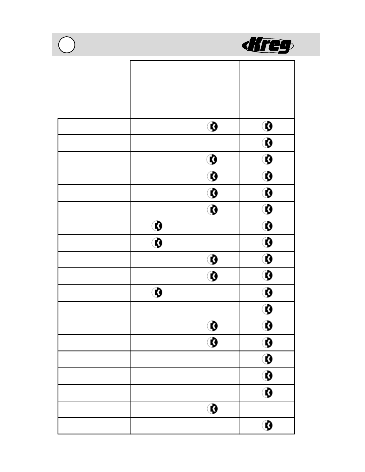
Package Contents
4-
- Indicates what is
included in package.
3/8” Step Drill Bit (KJD)
3”-#2 Square Driver Bit (D3)
6”-#2 Square Driver Bit (D6)
Allen Wrench - 1/8” (AW18)
Depth Collar (KJSC)
Premium Face Clamp (PFC)
Material Support Stop (KJSS)
K3 Upgrade Kit
K3 Standard Pack
K3 Master System
Dust Collection Shroud (NK3005)
Portable Base (NK3036)
K3 Drill Guide Block (NK3003)
Benchtop Base (NK3035)
SPS-C1 Screws
SML-F125 Screws
SML-C125 Screws
SML-C150 Screws
SML-C2 Screws
SML-C250 Screws
Standard Pack Case (NK3031)
Master System Case (NK3023)
4-
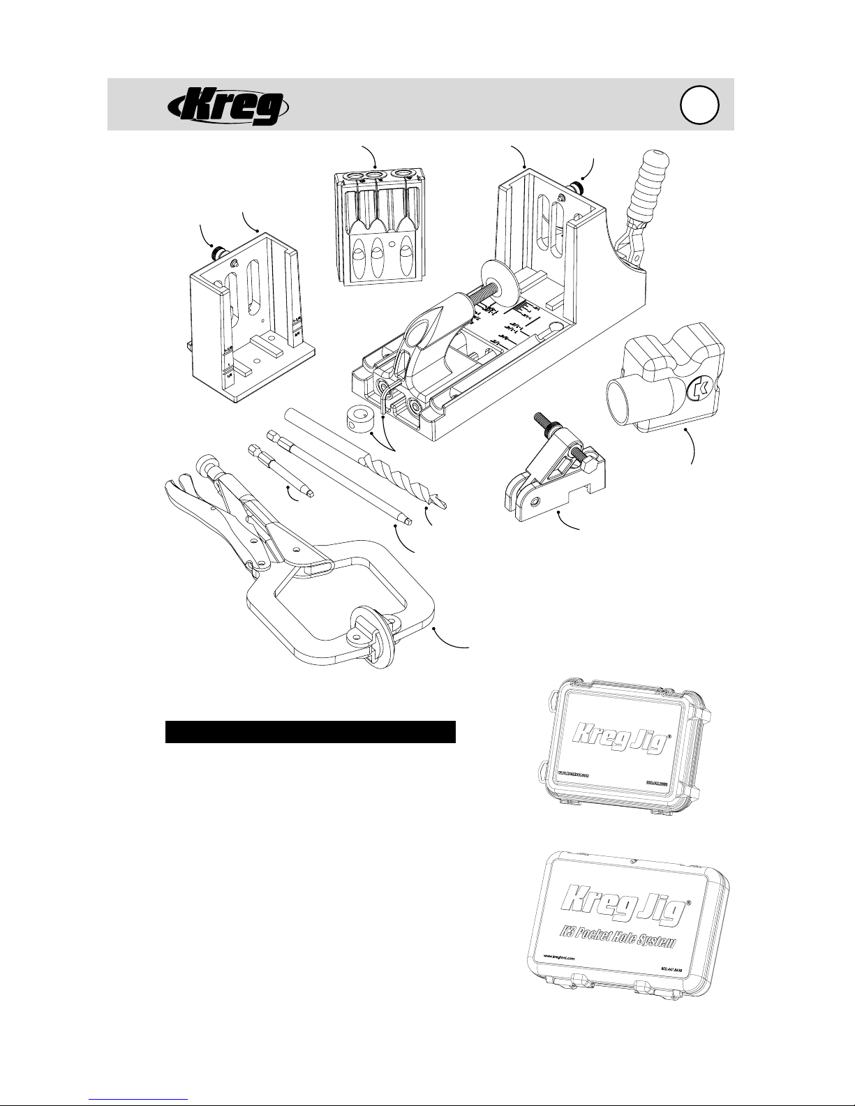
Parts Identifi cation
4
Brass
Index Pin
Portable
Base
K3 Drill Guide Block
3”-#2 Square
Driver Bit
Benchtop
Base
Depth Collar/Allen Wrench
3/8” Step Drill Bit
6”-#2 Square Driver Bit
Brass
Index Pin
Material
Support
Stop
Dust
Collection
Shroud
Part Number Description
KJD .................................
D3 ...................................
D6 ...................................
AW18 .............................
KJSC ................................
PFC .................................
KJSS ................................
NK3005 .........................
NK3009 .........................
NK3036 .........................
NK3003 .........................
NK3035 .........................
NK3031 ..........................
NK3023 .........................
3/8” Step Drill Bit
3”-#2 Square Driver Bit
6”-#2 Square Driver Bit
Allen Wrench - 1/8”
Depth Collar
Premium Face Clamp
Material Support Stop
Dust Collection Shroud
Brass Index Pin
Portable Base
Drill Guide Block
Benchtop Base
Standard Pack Case
Master System Case
Premium
Face Clamp
Standard Pack Case
Master System Case
5
Benchtop Base Assembly
4-
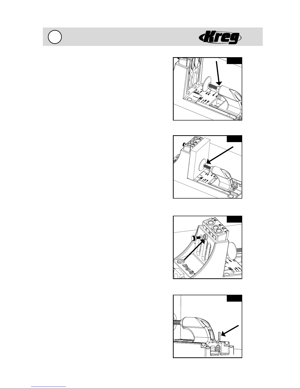
Attach the Clamping Pad (Fig. 5A&B)
1. Attach the Clamping Pad to the Clamp Follower
by simply threading the shaft of the Clamping Pad
into the threaded insert of the Clamp Follower.
2. The position of the Clamping Pad will be
adjusted for the thickness of the material to
be drilled. Proper position of the Clamping Pad
will be outlined in the “Getting to Know Your
K3 System” section.
3. You may notice that the Clamping Pad will
angle slightly upward once the Clamping Pad
is installed into the Clamp Follower. This is the
correct configuration of the Clamping Pad. The
Clamping Pad is angled slightly upward to assist
the clamping mechanism to insure the work
piece is seated tight against the Drill Guide Block
and flush with the Benchtop Base surface.
Attach the Index Pin (Fig. 5C)
1. Thread the Brass Index Pin into the threaded
insert contained in the upright of the
Benchtop Base.
2. Back off the Brass Index Pin so that the rounded
point of the Brass Index Pin is flush with the inside
of the upright surface.
3. The Brass Index Pin will be seated fully when the
Drill Guide Block has been inserted in the opening of
the upright and used to hold the Drill Guide Block
in position prior to clamping.
Fig. 5A
Hex nut on threaded shaft.
Fig. 5B
Clamping Pad clamped against board.
Fig. 5C
Store the Allen Wrench (Fig. 5D)
1. The 1/8” Allen Wrench is used to lock the
Depth Collar in position on the Kreg Jig® Drill
Bit for different depths of pocket holes.
2. The Allen Wrench may be stored either in the
designated location in the case or it can be held
conveniently in the rear of the Clamp Follower.
3. When using the Clamp Follower location be
sure to rotate the right-angled extension of
the Allen Wrench to a clock position between
9 o’clock and 3 o’clock. This will prevent the
Allen Wrench from being accidentally lost when
the Clamp Follower slides across the center rib
in the bottom of the Benchtop Base.
Inserting the Brass Index Pin.
Fig. 5D
Storage for the Allen Wrench.
4-
Portable Base Assembly
6
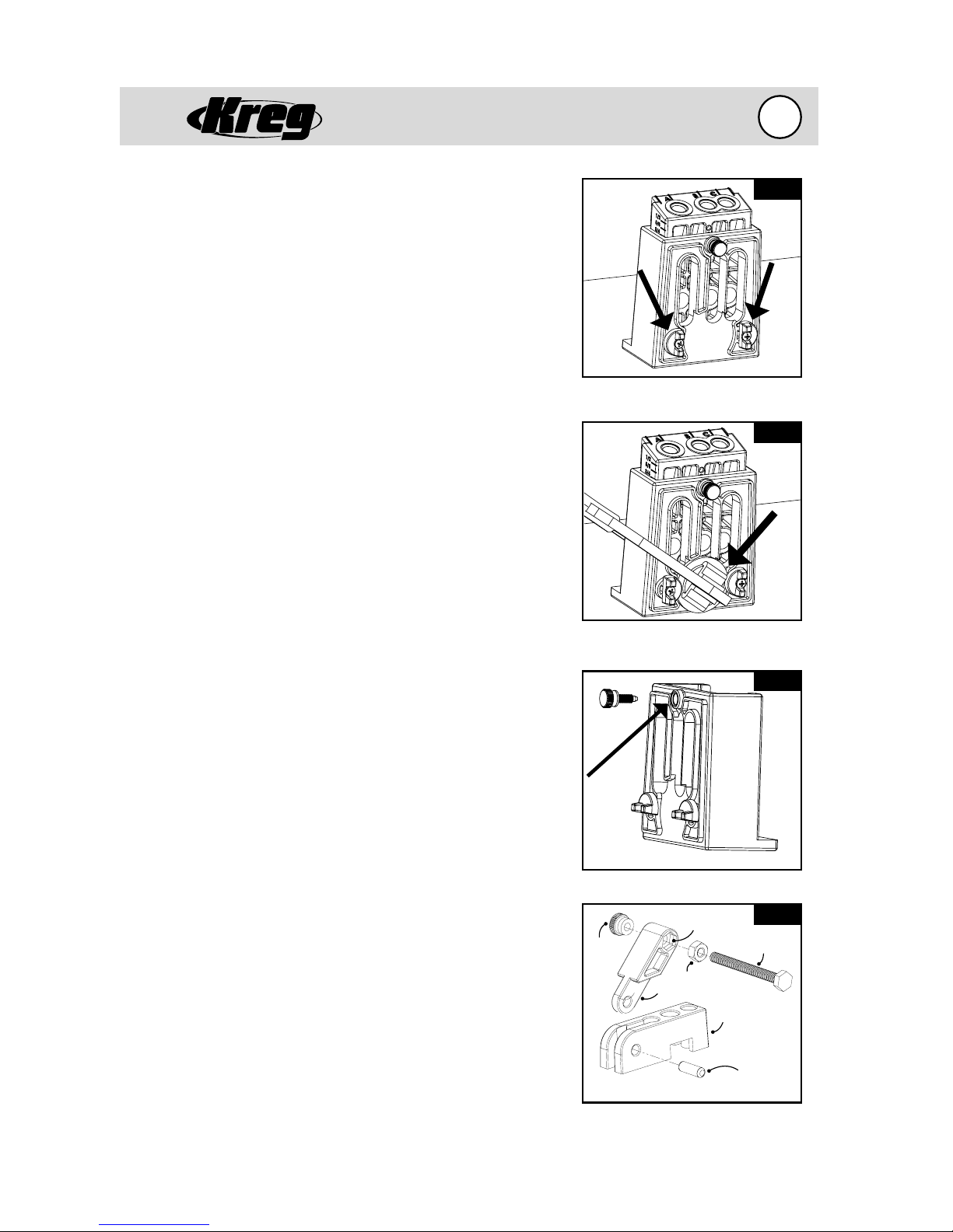
Attach the Locking Tabs (Fig. 6A&B)
1. Align the center-hole of each of the Locking Tabs to
the corresponding mounting hole on the rear vertical
surface of the Portable Base.
2. Insert a #6 x 3/8” screw through center-hole of each
of the Locking Tabs and tighten while still allowing the
Locking Tabs to move freely.
3. The smaller pad of the Premium Face Clamp will be
held in position on the Portable Base by rotating the
Locking Tabs so that they cover the outside surface
of the Premium Face Clamp pad. Proper position of
the Premium Face Clamp will be outlined in the
“Getting to Know Your K3 System” section.
4. You may notice that there are raised ribs on the rear
outside surface of the K3 Portable Base surrounding
the openings used for wood chip ejection. These
raised ribs are provided so that any clamp may be
used to secure the K3 Portable Base and Drill Guide
Block to the material to be drilled.
Attach the Index Pin
(Fig. 6C)
1. Thread the Brass Index Pin into the threaded insert
contained in the upright of the Portable Base.
2. Back off the Brass Index Pin so that the rounded
point of the Brass Index Pin is flush with the inside
of the upright surface.
3. The Brass Index Pin will be seated fully when the Drill
Guide has been inserted in the opening of the upright
and used to hold the Drill Guide Block in position prior
to clamping.
Fig. 6A
Locking Tabs on Portable Base.
Fig. 6B
Locking Tabs holding the Premium
Face Clamp in position.
Fig. 6C
®
Assemble the Kreg Jig
Support/Stop (Fig. 6D)
1. Slide the center tongue of the Support/Stop Arm
between the outside extensions of the Support/Stop
Base and align the pivot hole through all three
surfaces.
2. Insert the Pivot Pin through one outside surface
of the Support/Stop Base and either tap into place
with a mallet or a hammer and a block of wood to
prevent marring the end of the Pivot Pin. Continue
to advance the Pivot Pin until it is fully seated in the
Support/Stop Base and Support/Stop Arm. Push the
1/4”-20 Hex Nut into the side of the Support/Stop
Arm hex recess.
3. Thread the Nylon Stop Bolt from either side through
the Support/Stop Arm into the Hex Nut. Which side
will depend on which side of the Kreg Jig
®
that the
Support/Stop will be used.
4. Thread the Knurled Nylon Lock Nut onto the Nylon
Stop Bolt on the side of the Support/Stop Arm
opposite the Hex Nut. It may be necessary to thread
the Knurled Nylon Lock Nut onto the Nylon Stop Bolt
prior to threading the Nylon Stop Bolt into the Hex
Nut in some applications.
How to insert the Brass Index Pin.
Hex Recess
Knurled
Nylon
Lock
Nut
Support/Stop assembly diagram
Hex Nut
Arm
Fig. 6D
Nylon Bolt
Base
Pivot Pin
7
Quick-Start Guide...
To Building Your First Pocket Hole Joint
Ready to jump in and start building? Here is a quick-start guide to
creating your first pocket hole joint.
Before you start... a few Pocket Hole Joinery Facts
• You only need to drill a pocket hole into ONE of the workpieces to be
joined. No pre-drilling of the second workpiece is required with the use
of self-tapping screws.
• The step drill bit forms both a pocket hole for the screw head and a
guide hole for the screw shank in one motion.
• Gluing the joint is optional.
• Simply clamp the two workpieces to be joined to hold flush alignment
and drive the screw.
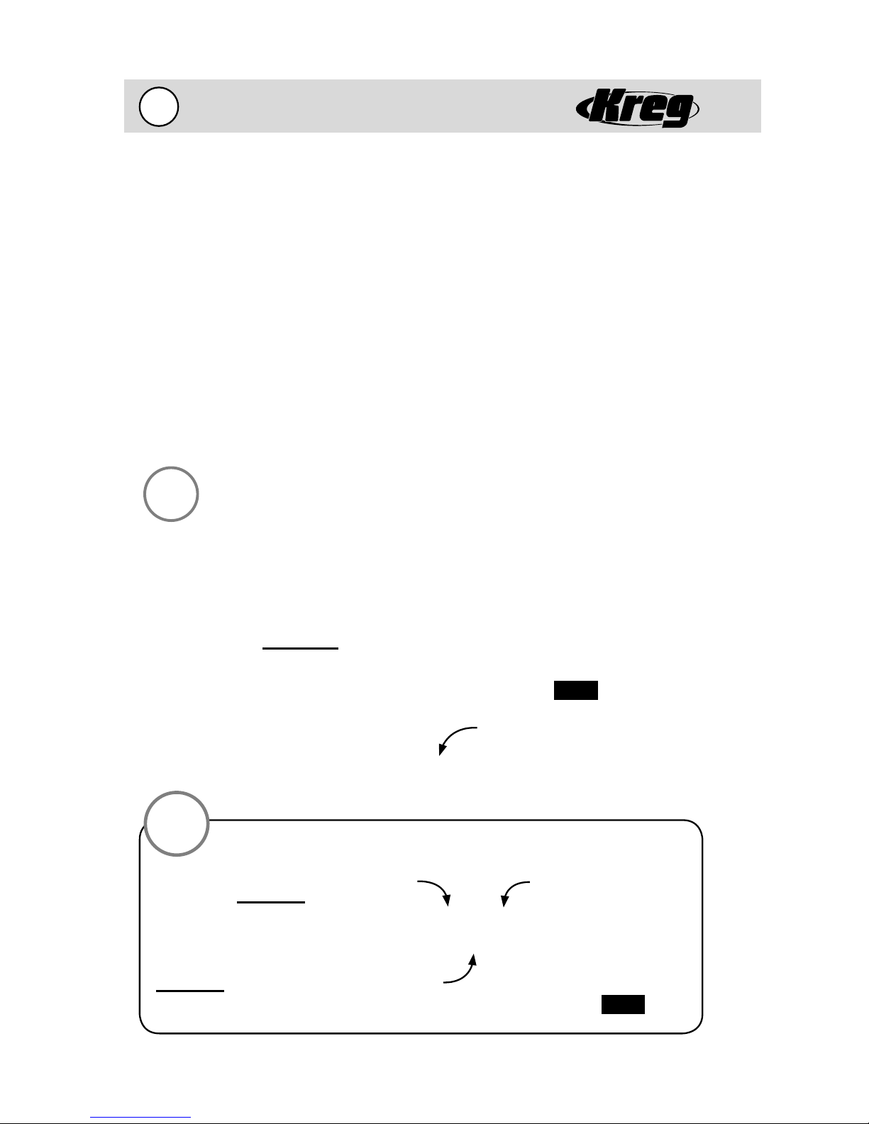
STEP 1 - Set the drilling depth.
(this example assumes using 3/4” thick material)
1.
4-
(CAUTION! Drill bit fl utes are extremely sharp! Handle with care.)
The first step in creating a pocket hole joint is to set the drilling depth of
your drill bit. Drilling depth is adjusted by changing the location of the depth collar
on the shank of the drill bit. For joining 3/4” thick material, place the depth collar
onto the shank of the drill bit. Use a tape measure to position the depth collar
3-9/16” from the SHOULDER of the drill bit. Tighten the depth collar in this posi-
tion with the Allen Wrench provided.
Fig. 7A
3-9/16”
Shoulder of Drill Bit
TIP
Setting the depth collar
closer to the SHOULDER of
the drill bit will result in less
screw travel into the second
workpiece, moving the depth
collar further from the
SHOULDER of the drill bit will
result in more screw travel.
Deeper Hole
Depth Collar
Shallower Hole
Fig. 7B
4-
Quick-Start Guide Cont.
8
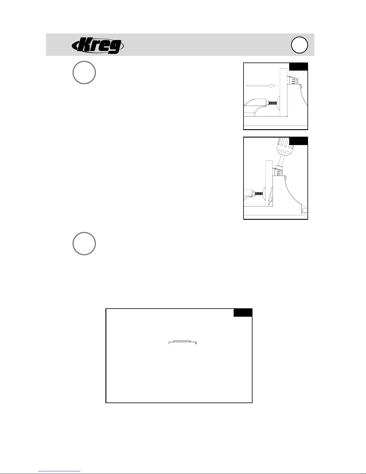
STEP 2 - Prepare wood and
drill the pocket holes.
2.
Prepare your wood by squaring the pieces to be joined
on all edges. Place the drill bit into your drill and tighten
securely. Place one workpiece to be joined onto the base
of the Kreg Jig® K3 as shown in Fig. 8A. Adjust the
clamping pressure of the clamp by turning the clamping
pad to firmly hold the workpiece into the jig. Next,
place the first 1-1/2” of the drill bit into any one of the
three drill guides making sure that the tip does not come
in contact with the workpiece. Bring the drill bit up to full
speed and slowly plunge the drill bit into the drill guide
until the depth collar reaches the top of the guide as
shown in Fig. 8B. Remove drill bit and drill the second hole
in an adjacent drill guide. Once drilling is complete,
unclamp and remove workpiece from jig, gently tapping
the workpiece to remove any remaining wood chips from
the holes you have just created.
Fig. 8A
Fig. 8B
STEP 3 - Drive screws to secure the joint.
3.
At this time, choose the correct screw length for your application. If you are
joining 3/4” material to 3/4” material, a 1-1/4” length screw is suggested. Add glue
to the joint line if desired. If you are joining the two pieces in a flat plane, such as
a frame, position the large pad of the Kreg Premium Face Clamp over the joint line
and clamp with firm pressure to hold them perfectly flush as shown in figure 8C.
Fig. 8C
Joint Line
Face Side
Large Pad
Place the self-tapping screws down into the pocket hole and drive with a cordless drill until tight. Your joint should be tight, flush and extremely strong. If you
encounter any problems, consult our FAQ section that begins on page 32.
9
Getting to Know Y our K3 System
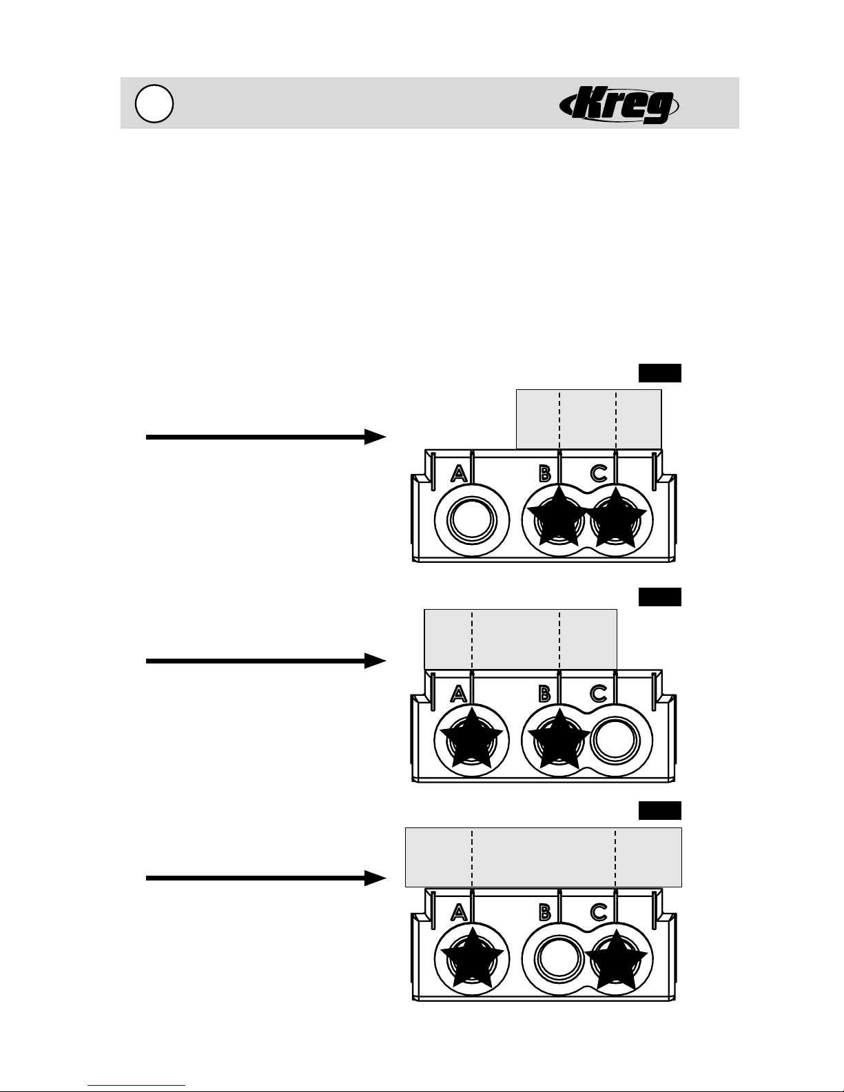
Choosing the Correct 2-Hole Spacing
Spacing pocket holes across the width of a workpiece is important in maximizing the
strength of a joint. When framing most woodworking projects, it is recommended
to place two pocket holes across the width of a rail to keep the workpiece from
twisting once it has been assembled. The patented three-drill guide fixed spacing of
the Kreg Jig® Drill Guide Block makes it extremely easy to place two pocket holes in
a workpiece without having to unclamp and move the workpiece to drill the second
hole. A real timesaver when working with a variety of wood widths. We recommend
using the drill guide spacings indicated below for each rail width. For very wide pieces
such as panels, we recommend placing a pocket hole every 6-8 inches across the
length of the panel. Use any of the three drill guides to form the pocket on panels.
Fig. 9A
Use B & C Spacing
On 1-1/4” to 1-3/4”
Material
4-
Use A & B Spacing
On 1-3/4” to 2-3/4”
Material
Use A & C Spacing
On 2-3/4” to 3-3/4”
Material
Fig. 9B
Fig. 9C
4-
Getting to Know Y our K3 System
10
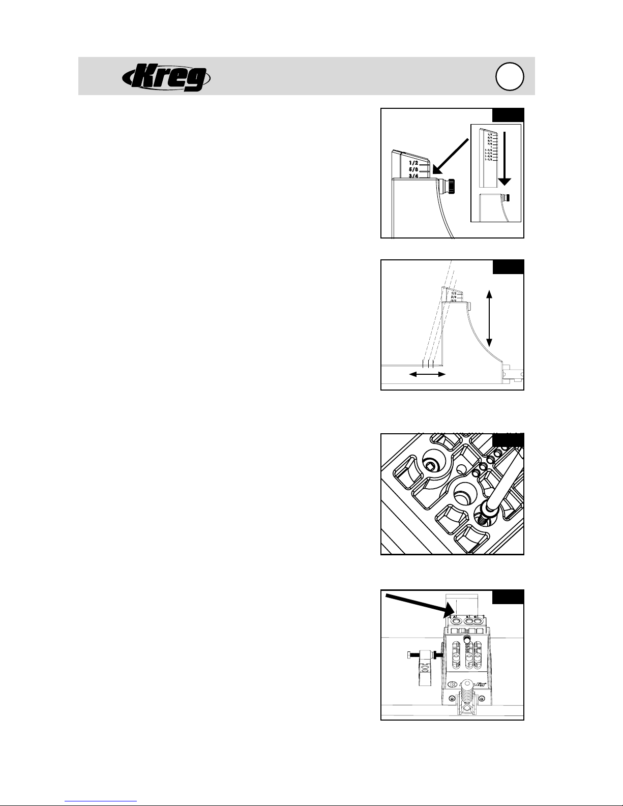
Adjusting the Drill Guide Block (Fig. 10A)
Lines molded into the side of the Drill Guide Block are
labeled with fractional designations that represent
the thickness of the material that is being drilled.
For example if you are drilling a pocket hole in 3/4”
material the line beside the marking of 3/4 is aligned
to the top of either the Benchtop Base opening or
the Portable Base opening.
Moving the Exit Point of the Screw (Fig. 10B)
As the Drill Guide Block of the K3 Kreg Jig® is raised
vertically, the exit point of the screw projects out
further from the base of the jig. The key here is
that the 15 degree drilling angle remains constant.
The result is that as you move the upright to your
desired material thickness setting, the screw will
automatically be aligned to exit on the centerpoint
of the workpiece.
Using the Drill Guide Block Separately (Fig. 10C)
There are times when it is not convenient to use
one of the bases specially designed for the Kreg Jig®
K3; or it is awkward to clamp the Drill Guide Block in
position. For these occasions the Drill Guide Block has
been specially designed to accept two SML head style
screws to hold the Drill Guide Block in position while
drilling the pocket hole.
(CAUTION! You must use the center drill guide
hole (“B”) when peforming this operation.)
Fig. 10A
Drill Guide Block markings.
Fig. 10B
Constant
15 deg.
angle
As the Drill Guide Block is raised,
the exit point of the screw projects
further from the base of the jig.
Fig. 10C
Centerlines on the Drill Guide Block (Fig. 10D)
Markings on the top surface of the Drill Guide Block
designate the centerlines of the three drill guides.
These markings also align with corresponding
markings on the surface of the Benchtop Base.
To place a pocket hole in a specific location, mark a
board with a pencil in the desired location, then align
the pencil mark with the corresponding centerline
marking on the Drill Guide Block or Benchtop Base.
Drive screws into chip extraction
holes to hold jig in position.
Fig. 10D
Pencil mark aligned with centerline
of Drill Guide Block.
 Loading...