

Kreg Jig K2000 ProPack Instruction Manual
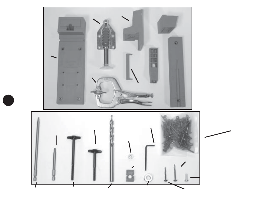
Base
Toggle
Clamp
Upright
1-1/2" Riser block
2
6" Driver
3" Driver
3-3/4" T-bolt
Face clamp
2-1/2" T-bolt
3/8" KJD bit
1/2" Step block
Allen wrench
1/4-20 Hex nut
Nut retainer
Depth collar
(2) Wing supports
Mini Kreg Jig
Sample pack of screws
(4) 1-1/2 Screws
(4) 10-32 x 3/4"
Machine Screws
(4) 1-1/4" Screws

Thank you!!!
Thank you for purchasing the Kreg Jig K2000 ProPack from Kreg Tool Company. For
over a decade, Kreg Tool has worked to make woodworking faster, stronger, and simpler using
pocket hole joinery. The K2000 Kreg Jig you have purchased is loaded with features that make
it the most versatile pocket hole system available.
Kreg Tool welcomes your ideas and comments. To contact us please call 1-800-4478638, or visit our web site at www.kregtool.com. The web site now includes a pocket hole
joinery forum where employees of Kreg Tool and other woodworking enthusiasts can get
together to solve problems and gather useful information.
Important Notice
Before drilling any parts with your Kreg Jig K2000, assemble the upright onto the base
in Position 1, adjust your depth collar for 3/4" material on your drill bit, and drill out each of the
holes. This process will remove blue plastic chips from the drill guide path. The chips are
perfectly normal and occur because of the tight tolerances placed on the drill guides and the path
of the drill bit. Blue chips will continue to be seen for approximately the first 20 holes.
Warranty
The Kreg Jig K2000 comes with a 30 day satisfaction guarantee. If you are unhappy
with the performance of the jig in any way, simply return it within 30 days for a full refund.
Both the K2000 and the Mini Kreg Jig included in this ProPack carry a lifetime warranty on
their hardened steel drill guides.
3

Assembly Instructions
Nut Retainer
Hexagonal recess
Step 2
Step 1
Please follow these simple steps in order to prepare
your Kreg Jig for use. Refer to the photo on page 2 of this
manual for part reference.
1. Step 1, press the hex nut into the hex recess on the bottom
of the jig base. Step 2, then push the plastic nut firmly onto
the ribs to capture the nut as shown in fig. 1.
2. If the toggle clamp is not already assembled, use the 4
machine screws to attach it to the base.
3. Next, you’ll want to screw the base down to a piece of
4
plywood using the four 1-1/2" screws provided. The plywood will serve as a mobile base
that will allow you to easily transport the jig around your work area. Simply clamp the
plywood to your workbench when ready to drill.
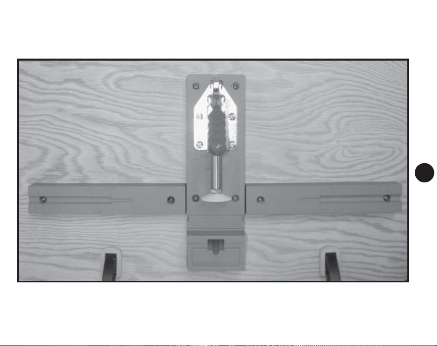
4. Locate the 2 support wings and place them perpendicular to the base so that they appear as
shown at right. Notice that the support wings are positioned to the forward edge of the
1/2" Step Block groove. Positioning them as shown will assure that the groove does not
become filled with wood chips while drilling. Finally, screw the wings tight to the plywood
using the (4) 1-1/4" screws provided. The wing supports serve two purposes: 1. They help
to support panels that are wider than the base of the jig. 2. They incorporate a groove that
is used to help locate the correct depth collar setting.
fig. 1
5
Kreg Jig K2000 Philosophy
Pocket hole joinery has
come a long way in the last
decade. An astounding number
of woodworkers are realizing
what we’ve known for many
years–that the fast, strong, and
simple technique that was
primarily used in face frame
assembly can be utilized in many
different woodworking applications. To better
serve the growing number of woodworkers that
use pocket hole joinery as their main joinery
6
method, Kreg worked to design a pocket hole
tool that easily places pocket holes in their ideal
location. The innovative design of the K2000
has produced a tool that provides three easy
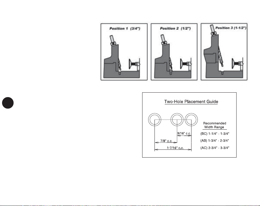
adjustments for working with different thicknesses of material as well as three horizontal
hole spacings to properly place holes in material
of varying widths. In addition, the Mini Kreg
Jig that is included in this ProPack can be used
virtually anywhere. Simply clamp the jig flush to the edge of your workpiece, adjust depth
collar setting, and drill to achieve the Position 1 result. Adjust the distance from the edge of your
workpiece accordingly for thicker or thinner materials and change your depth collar setting.
fig. 2
A
B
C
fig. 3

Set-up for Position 1
**Position 1 assumes standard 3/4" thick material using
1-1/4" screw. However, use this position for material ranging
between 3/4" and 1-1/8" in thickness. (You may need to adjust
screw length as material thickness varies.)
1. Set up base and support wings as shown on page 5.
2. Place the upright onto the base and finger tighten
using the 2-1/2" T-Bolt provided until parts are snug.
3. When using 3/4" material, the depth collar can be
set by aligning the step of the drill bit with the
3/4" marking on either wing support. Then use the
allen wrench to tighten the depth collar flush with
the end of the wing support as shown in fig. 5.
This setting leaves approximately 1/8" between the
tip of the bit and the base of the jig. (The depth
collar setting on the wing supports is a standard
setting only. Difference in screw length as well as
material thickness may cause need for adjustment.
Always check your setting before drilling final holes
as shown on page 8, fig. 7.)
4. Depending on which width of material you will be
drilling, either choose the AB, AC, or BC hole
spacings shown in fig. 6. Center the appropriate two
holes over the width of your material.
fig. 4
7
fig. 5
A
B
C
fig. 6

Drilling the Pocket Hole
Because variations in wood thickness and screw length can cause undesired results in
the screw protruding through the final workpiece, always check depth collar setting by testing in
scrap material and adjust depth collar accordingly (as shown in fig. 7). To set the correct
clamping pressure, spin the bumper in or out of the clamp’s barrel until the handle snaps closed
with two fingers of pressure. Once adjusted correctly, tighten the hex nut. Drill the pocket hole
by sliding the bit into the guide allowing the drill to achieve full
speed before pushing into the material. Once the depth collar has
made contact with the top of the drill guide, keep the drill turning at
full speed and withdraw the drill bit from the guide. It is recommended to use a 2000+ RPM corded drill in order to maximize drill
bit life.
8
fig. 7
Assembling the Joint
Self-tapping pocket hole screws eliminate the need to bore an aligning pilot hole in the
mating workpiece, even in hardwoods lik e oak, hick ory and maple. Although other types of
screws may work, pocket hole scre ws greatly reduce splitting and are hardened to nearly eliminate
breakage. We recommend using glue unless the ability to disassemble the joint is desired.
Using the 6" Face Clamp included to align the workpieces, as shown below, ensures
that the joint stays flush as the screws are driven. Place the large washer on the face of the joint,
increase tension, and clamp. The washer will help to keep the face flush if the workpieces are of
slightly different thicknesses, and will also keep the clamp from denting the face of softer materials.

It is strongly recommended to drive the screws using a drill with a clutch. The
clutch allows you to vary how much torque the drill puts on the screws so you don’t have
strip out. Most cordless drills include this feature. If you do not have a drill with a clutch,
you can use a corded drill to drive the screws until they are almost seated, and then finish
driving the screws using a hand driver.
When driving the screws, you may notice a slight separation of the work pieces
before the screw begins to pull them back together. This is normal, but if the gap exceeds
1/4" increase the clamp pressure. The face clamp works well for aligning face frame and
picture frame style joints. For other joints a bar clamp will be useful to keep the
workpieces in position while driving the screws.
A good tip for joining workpieces is to build a grid similar to the one shown in fig.
8. The grid allows you to suspend the joint above the table top
where you can reach it from both sides with the face clamp. The
grid also keeps your tools, screws and glue easily accessible
between the 2x4’s, yet out of the w ay when sliding the frame
around. Make the grid using a sheet of 3/4" plywood cut to any
dimension, with 2x4’s pocket-holed on edge to the sheet. Vary
the spacing of the 2x4’s.
fig. 8
9

Set-up for Position 2
**Position 2 was primarily designed for use with standard 1/2"
thick material. This type of stock is widely used in drawer construction.
To attach workpieces, plan on using 1" screws. You will also want to use
this position for material ranging between 1/2" and 5/8" in thickness.
(You may need to adjust screw length as material thickness varies.)
1. Set up base and support wings as shown on page 5.
2. Press the 1/2" Step Block into place.
3. When using 1/2" material, the depth collar can be
set by aligning the step of the drill bit with the 1/2"
marking on either wing support. Then use the allen
10
wrench to tighten the depth collar flush with the end
of the wing support as shown in fig. 10. This setting
leaves approximately 1/8" between the tip of the bit
and the base of the jig. (The depth collar setting on
the wing supports is a standard setting only. Difference in screw length as well as material thickness may
cause need for adjustment. Always check your setting
before drilling final holes as shown on page 8.)
4. Depending on which width of material you will be
drilling, either choose the AB, AC, or BC hole
spacings shown in fig. 11. Center the appropriate two
holes over the width of your material.
A
fig. 9
fig. 10
B
fig. 11
C

Set-up for Position 3
**Position 3 assumes standard 1-1/2" thick material using
2-1/2" screw. However, use this position for material ranging between
1-1/2" to 2" in thickness. (You may need to adjust screw length as
material thickness varies.)
1. Set up base and support wings as shown on page 5.
2. Locate the 1-1/2" Riser Block from the ProPack case. Press
the Riser Block into position on the base and then assemble
the upright on top of the Riser Block using the 3-3/4"
T-bolt. Finger tighten until all parts become snug.
3. When using 1-1/2" material, the depth collar can be set
by aligning the step of the drill bit with the 1-1/2"
marking on either wing support. Then use the allen
wrench to tighten the depth collar flush with the end of
the wing support as shown in fig. 13. This setting
leaves approximately 3/4" between the tip of the bit and
the base of the jig. (The depth collar setting on the
wing supports is a standard setting only . Dif ference in
screw length as well as material thickness may cause
need for adjustment. Al ways check your setting before
drilling final holes as shown on page 8.)
4. Depending on which width of material you will be
drilling, either choose the AB, A C, or BC hole spacings
shown in fig. 14. Center the appropriate two holes o ver
the width of your material.
A
fig. 12
B
11
fig. 13
C
fig. 14

Choosing the Right Screw
Choosing the right screw is largely a matter of experi-
mentation, however some guidelines do exist.
1. Thread - Our screws are designed so that a fine thread
screw is to be used in hardwoods, and a coarse thread screw
is used in softwoods and composite material (plywood,
particle board, MDF).
2. Length - 1-1/4" is standard length for 3/4" materials. Use
1" screws when working with 1/2" thick material. A 2-1/2"
screw is recommended when working with 1-1/2" thick
12
material. All screws are available in a Sun Seal weather
resistant finish. Call for details.
3. Maxi-loc Screws - The washer head keeps the screw
head from crushing into the bottom of the pocket hole and
seating the screws deeper than desired. Use a coarse thread
washer head when joining any combination of soft materials
like pine, plywood or particle board. Use a fine washer head
screw when the pocket hole is bored in a soft material and
passes into a hard material (i.e., edge-banding or partition to
face frame).
Maxi-Loc Fine
fig. 15
Maxi-Loc Coarse
fig. 16

Applications
With the almost limitless settings and adjustability of the K2000
ProPack, application data has grown tremendously. The following are some
of the most common in use today.
Face Frames
Using pocket hole joinery for face frames is faster and stronger
than conventional methods (dowel, biscuit and even mortise and tenon), and
frees you from having to simultaneously manipulate several bar clamps as
the frame is clamped for glue-up.
Angled Joinery
Using pocket hole joinery to make angles and curves eliminates
difficult clamping set-ups and the expense of specialized clamps. To form
any angle up to 45 degrees, rather than cutting half the desired angle
on both workpieces, the entire angle is cut on the mating workpiece
(right), which provides more distance for the screw. Before drilling
the pocket hole make sure the depth collar is set correctly by checking a piece of scrap.
Cutting the entire miter on only one workpiece makes its
edge longer than the edge of the first workpiece. This o verhang is to
be removed with a jointer, sander, or hand plane. Notice in
fig. 18 that the point of the joint shifts away from the glue-line.
When making face frames assemble your angled stiles first, remove
the overhang, and then complete the face frame. A simple jig, as
pictured at right, makes it easy to screw the workpieces together.
pocket holes
mating work piece
shim
workbench
pocket
holes
fig. 17
overhang
glue-line
shim
height
13
fig. 18
fig. 19
clamp

Curves
The same technique used to form angles is also used for curves,
except a shallower angle between 5 and 15 degrees is typically used as shown
at right. The smaller angle creates a smaller overhang, and a belt sander is
used to smooth the face. This technique can be used for both solid wood and
curved panel work as well.
Beveled Ninety Degree Corners
Trying to join two workpieces, each with 45 degree miters, to form a
90 degree corner is not a good application for the pocket hole joint. However,
a 90 degree change of direction can be accomplished using pocket hole joinery
with the 90 degree bevel joint shown at right. The joint consists of a center
14
workpiece with a 45 degree miter on both edges.
Table Tops and Aprons
When making table tops a bar clamp is helpful to hold the work in
position as the screws are driven.
Edge-Banding Countertops or Shelving
Pocket holes are a great, sometimes overlooked solution for edgebanding countertops and shelving made from either plywood or particle board,
as shown at right.
fig. 20
fig. 21
fig. 22
fig. 23

Mitered Corners
Using pocket hole joinery for a mitered corner eliminates
the need for frustrating and expensive clamps. For narrower frames
a single pocket hole can be used. Cut the miter and rout the rabbet
before boring the pocket holes. Use a face clamp to align the joint
and drive the screws. Notice in the drawing at right that the holes
are not necessarily drilled perpendicular to the joint line. This is
accomplished by lifting one edge of the workpiece off the base of
the jig as shown. This technique is especially helpful when working
with stock less than 2" wide. One inch screws are useful when
making mitered corners.
Window and Door Jam Extensions
A great time saver and something that can easily be
accomplished in the field.
Stairs
Extremely solid stair construction. Pocket holes can be
bored into existing stairs to eliminate squeaks.
fig. 24
fig. 25
15
fig. 26
fig. 27

Post (Leg) and Rail Leg
Table and chair legs are extremely strong and easy to
construct with pocket hole joinery. Cut the miters for the brace after
drilling the pocket holes.
Traditional Style (Framed Cabinets)
Pocket hole joinery can be used for almost every facet of
framed cabinet construction, as shown at right. The traditional
technique calls for making the face frame and case as separate
components, and then fitting the two together, creating substantial
opportunities for error. Because of the strength of pocket hole
joinery, cabinet end-panels and partitions can be attached directly to
the face frame one component at a time making construction much
16
simpler. Also, the strength of pocket hole joinery eliminates the
need for dadoes and rabbets that are usually cut into the face frame
for the partitions and end-panels, making construction easier.
Euro-Style (Frameless) Cabinets
Pocket hole joinery works well for Euro-style (frameless)
cabinetry, as shown at right. Use #SML-C125 (#7 coarse) screws
for greater holding power.
Shelving
Pocket holes work great for shelving with or without
a dado.
fig. 28
fig. 29
fig. 30

Outdoor Applications
The K2000 makes working with dimension material easier than ever. Pocket holes help to
hide the fastener from exposure to the elements. Because water can no longer pool around the head
of the fastener and seep into the core of the wood, the fastener and the wood last much longer.
Project Plans / Videos
To get the most out of your Kreg Jig ProPack, consider purchasing one of our pocket hole
plan sets or instructional videos. The plan sets include step-by-step instructions in a large, easy to
read format that will have you building professional quality projects in no time. Be sure to check
with your local dealer or www.kregtool.com for the most up to date listing of projects av ailable.
17

Mini Kreg Jig
The Mini Kreg Jig is
provided in the ProPack as a
portable companion to the
K2000. Simply clamp the jig
flush to the edge of your
3/4"workpiece, adjust depth
collar setting, and drill to
achieve the Position 1 result as
shown at right. Adjust
accordingly for thicker or
thinner materials and change
your depth collar setting.
18
also incorporates a plug setting
feature into its design. Load
the plug into the groove on the
underside of the jig (1),
position it in the center of the
pocket hole and press into
place (2). Pre-cut pocket hole
plugs are available in a variety
of species from Kreg.
The Mini Kreg Jig
1.
2.

Other Products Available From Kreg Tool
For maximum performance from your Kreg Jig ask your dealer for genuine Kreg tools
and accessories. If there is not a Kreg dealer near you, or your dealer can’t supply you with
genuine Kreg accessories, please call 1-800-447-8638 or visit www.kregtool.com.
Maintenance
Place a drop of oil in hardened steel drill guides when dry, or every 250-500 holes.
Keep your drill bits sharp. It is recommended that you sharpen your bits after
approximately 750-1000 holes. Kreg Tool provides a bit sharpening service for a small fee.

Kreg Tool Company, 201 Campus Drive, Huxley, Iowa 50124
www.kregtool.com
 Loading...