

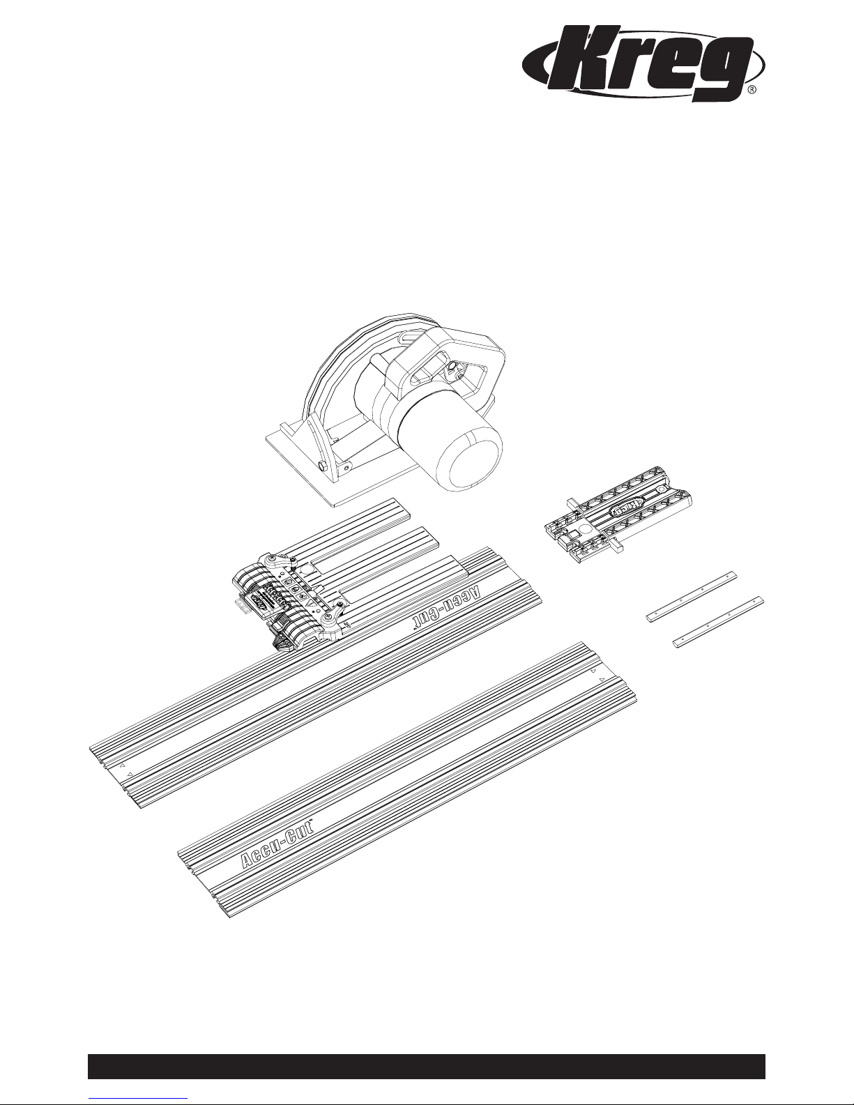
Kreg Accu-Cut KMA2700 Owner's Manual
Accu-Cut
™
Owner’s Manual
Guide d’utilisation
Manual del propietario
NK9191
Version 2 - 06/2017
www.kregtool.com • 800.447.8638
Item# KMA2700
Article KMA2700
Artículo # KMA2700
Saw not included
General Safety Guidelines
!
WARNING When using electric tools, always follow the safety precautions below to reduce the risk of re, electric shock,
and personal injury. Read all these instructions before attempting to operate this product. SAVE THESE INSTRUCTIONS.
• Before using the Accu-Cut™, read, understand, and follow the safety
warnings and operation instructions included with this product and provided
by your saw manufacturer. Keep all guards and safety devices in place.
• Wear proper eye, ear, and respiratory protection when operating your saw.
• Use a sharp blade designed for the type of material you are cutting.
• Always disconnect your saw from power before making adjustments
to the saw or Accu-Cut™.
• Wipe the guide strips with a damp cloth and remove dust and debris
from the workpiece before positioning the track on the workpiece.
• The Accu-Cut™ is designed for use with both tracks joined together.
Do not attempt a cut using only one track section without rst clamping
the track section to the work piece.
• Ensure that the saw blade will not contact the aluminum track during the cut.
• Do not attempt a cut when any part of the Accu-Cut™ interferes with
the operation of the saw blade guard.
• Fully support both the workpiece and the cutoff piece to prevent
binding and kickback.
• Adjust the depth of cut so the saw blade protrudes ⅛″ [3mm] through
the workpiece during the cut.
• Keep your hands away from the saw blade during operation.
• Secure your workpiece to ensure it doesn’t move during the cut.
• Do not use excessive force when cutting. Maintain a steady
and controlled pace.
• Allow the saw blade to come to a complete stop before removing the
saw/sled assembly from the track.
• Do not leave unattended saw resting on the track or starting block.
• Maintain your tools and accessories. Check for misalignment or binding of
moving parts, loose fasteners, broken parts, and any other condition that may
affect safe operation. If an unsafe condition is discovered, correct it before use.
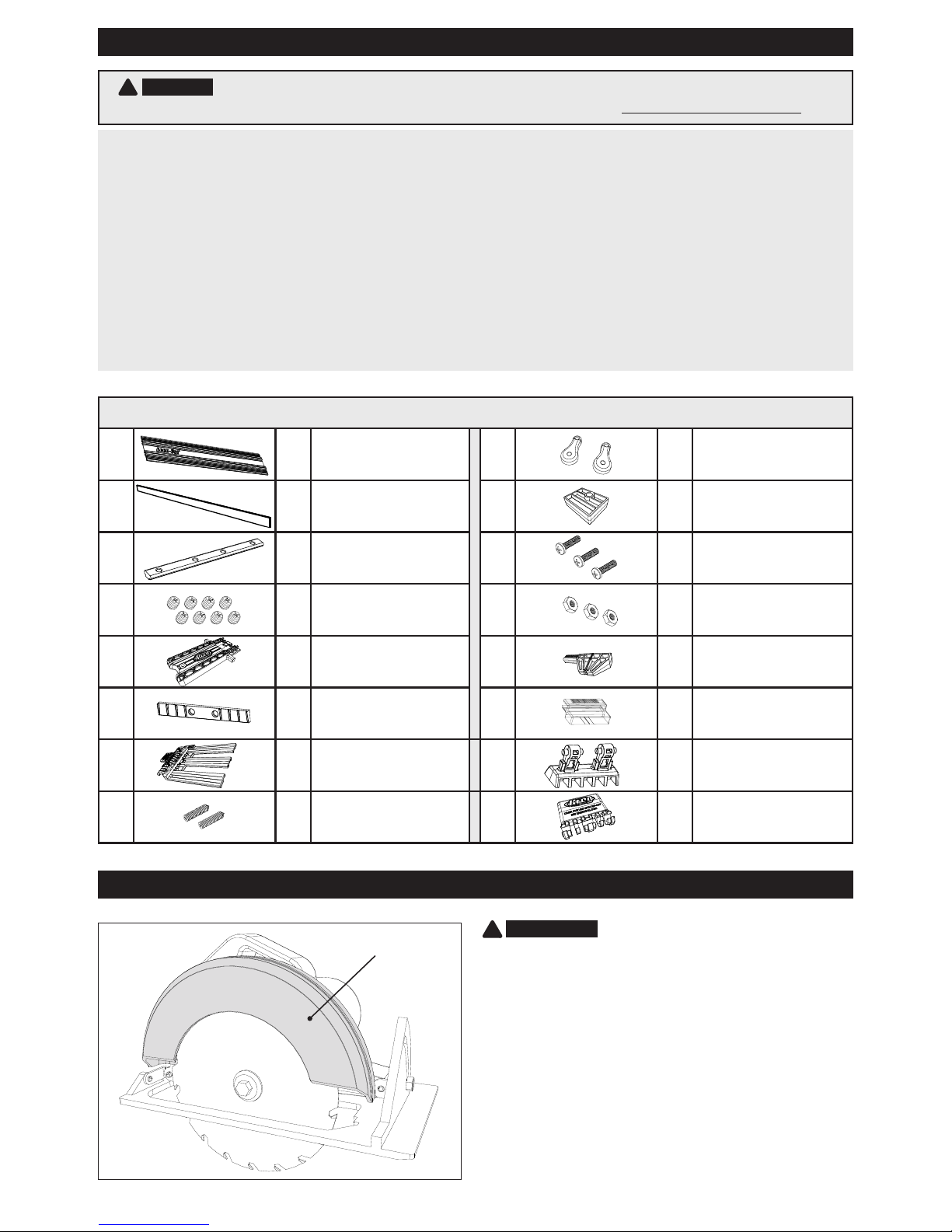
Parts
A 2
Tracks
I 2
Base-plate Clamps
B 4
Guide Strips
(Pre-Installed)
J 1
Indexing Stop
C 2
Connector Bars
K 3
Machine Screws
D 8
Set Screws
L 3
Hex Nuts
E 1
Starting Block
M 1
Indicator Clip
F 1
Filler Strip
N* 1
Cursor
G 1
Sled
O* 1
Wedge
H 2
Set Screws
P* 1
Handle
*Part functional only on Kreg Rip-Cut™.
Upper blade guard
Before You Begin
Welcome to the Kreg Accu-CutTM!
With your new Accu-CutTM, you are sure to have a
lifetime of quality cutting experience. The Accu-Cut is
designed to work best with circular saws that have
a metallic upper blade guard. Saws with a plastic
upper blade guard may allow excessive deection
between the blade and the base plate causing
undesirable results when paired with the Accu-CutTM.
Please check the upper blade guard on your circular
saw. If your upper blade guard is plastic, Kreg
recommends not using this circular saw with the
Accu-CutTM.
!
ATTENTION
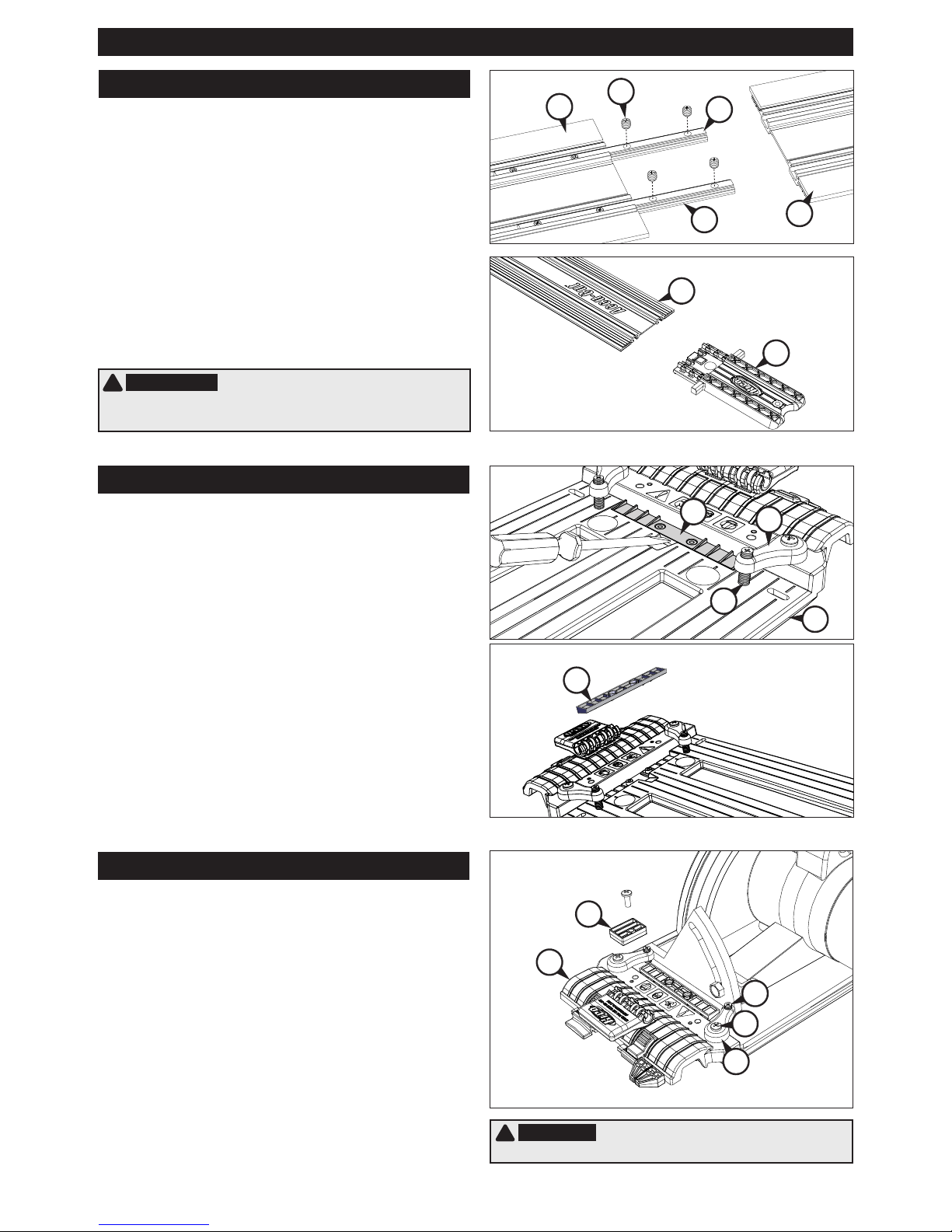
1
Turn the two tracks (A) upside down (black faces
of the guide strips up). Slide the connector bars
(C) halfway into the T-slots in the rst track at the end
with the indicator arrows on the top face and tighten
the set screws (D). Slide the second track onto the
connector bars so the indicator arrows on the top face
align with those on the rst track section. Tightly hold
the two tracks together and tighten the remaining set
screws. Slide the starting block (E) into the T-slots at
the end of one track.
Assemble the track
D
C
C
E
A
A
A
I
H
G
I
K
H
G
J
F
F
!
ATTENTION The tracks can be taken apart for storage.
If you disassemble the tracks, align the indicator arrows on the
top faces of the tracks when reassembling them.
!
WARNING Disconnect the saw from power before
mounting it on the sled.
2
The ller strip (F) on the sled (G) is shipped with
the angled ribs facing up. These ribs support a
saw base with an angled leading edge, keeping the
saw base at on the sled when the set screws (H) in
the base-plate clamps (I) are tightened. For a saw
base with a at leading edge, lift the ller strip from
the sled recess with the tip of a screwdriver, turn
it over to expose the at face, and press it into the
recess.
3
Remove the indexing stop (J) from the sled (G).
Loosen the set screws (H) in the base-plate
clamps (I) and slide your saw base plate under them.
Position the saw on the sled with the front of the saw
base plate against the step at the front of the sled. For
saws with the blade on the left-hand end of the motor,
center the blade in the left sled slot. For saws with the
blade on the right-hand end of the motor, center the
blade in the right sled slot. To accommodate different
saw base-plate congurations, there are two holes for
attaching each base-plate clamp to the sled. For the
most secure clamping, choose the holes that provide
widest spacing allowed by your saw. The clamps can
be oriented at an angle. Tighten the set screws onto the
saw base plate just enough to hold the saw in place.
Assembly
Orient the Filler Strip
Mount your Circular Saw on the Sled
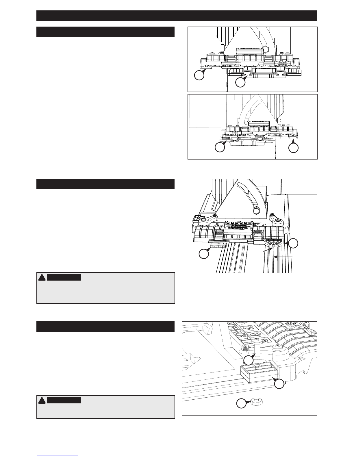
5
There are two positions on the sled for the
indicator clip (M) and cursor (N*) that correspond
to the two sled slots. Position the cursor in the holder
in front of the saw blade and the indicator clip in
the other holder. To switch indicator clip and cursor
positions, press down on the holder locks, slide
the indicator clip and cursor out of the holders and
reinstall each one in the other holder. For ease in
positioning the saw/sled assembly on the starting
block, align the notch at the front of the indicator clip
with the groove in the track rail.
Assembly
Check the Position of the Indicator Clip and Cursor
*
6
The indexing stop (J) allows you to remove the
saw from the sled assembly and then re-mount it
in exactly the same position without having to re-trim
the guide strip. Place the indexing stop against the
side of the saw base and secure it to the sled with
the machine screw (K) and nut (L). For maximum
positioning exibility, the sled is slotted and the
indexing stop can be rotated 180°.
Reinstall the Indexing Stop
N*
K
J
L
M
Groove
Notch
!
ATTENTION When mounting a different saw on the sled
repeat Steps 2-6. When installing a different blade in the saw,
repeat Step 4.
!
ATTENTION The sled assembly is equipped with
features only functional on the Kreg Rip-Cut™. Additional steps,
found in the Rip-Cut™ manual, are required to calibrate this sled
for use on the Rip-Cut™.
*The cursor is functional only on the Rip-Cut™.
A
A
G
G
4
There are three grooves in the bottom of the sled
(G). For a saw with the blade in the right-hand
sled slot, the center and left grooves ride on the track
(A) rails. For a saw with the blade in the left-hand sled
slot, the center and right grooves ride on the track rails.
Position the saw/sled assembly on the starting block,
engaging the appropriate sled grooves. Loosen the
base-plate clamp (I) set screws (H) enough to slide the
saw side to side. Align the saw so the blade will shave
about 1⁄32″ [.8mm] off the guide strip. (You’ll trim the
guide strip later for zero-offset positioning of the track.)
Tighten the base-plate clamp set screws enough to
securely hold the saw, but do not over tighten. Make
sure the saw blade guard operates freely.
Align the Saw/Sled Assembly on the Track
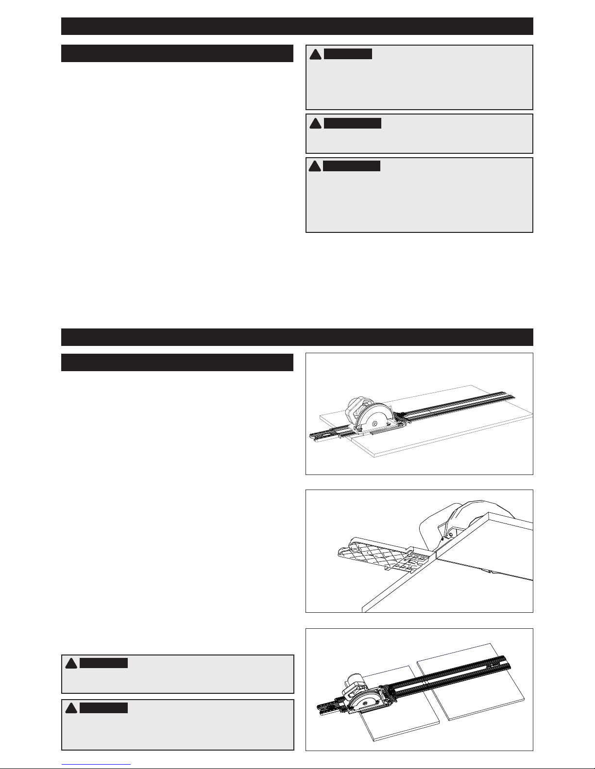
Using your Accu-Cut™
Using your Accu-Cut™
7
The tracks (A) are supplied with the guide strips
(B) already installed. The guide strips grip the
workpiece surface to ensure the track does not move
during use. When properly trimmed, the guide strips
allow you to align the edge of the strip with the cutline
and provide zero-clearance support next to the blade
to minimize chip-out.
To allow positioning the edge of the guide strip on
the workpiece cutline (zero offset), position and fully
support the track on a 48″ [1219mm]-long scrap
workpiece with the edge stop on the bottom of the
starting block against the edge of the workpiece.
Position the saw/sled assembly on the starting block
using the indicator clip to ensure proper alignment
and engage the track rails. Adjust the depth of cut
so the blade will protrude ⅛″ [3mm] through the
workpiece during the cut. With the blade clear of the
workpiece, turn on the saw. Applying light downward
pressure on the saw and maintaining a steady,
controlled pace, trim the guide strip and workpiece
along the entire length of the track. Turn off the saw
and allow the blade to stop before removing the saw/
sled assembly from the track.
Trim the Guide Strip
!
ATTENTION Always wipe the guide strips with a
damp cloth and remove dust and debris from the workpiece
before positioning the track.
1
For the best results, install a 40-tooth blade on
your saw
2
Mark the cutline on your workpiece. Position
the track with the edge of the guide strip on
the cutline and the starting block edge stop against
the edge of the workpiece. Always make cuts with
the workpiece under the track and the waste to the
outside.
3
Place the saw/sled assembly on the starter
block, using the indicator clip to align the sled
with the track. Adjust the depth of cut so the blade will
protrude ⅛″ [3mm] through the workpiece during the
cut.
4
Connect your saw to power. With both hands on
the saw and the blade clear of the workpiece,
turn on the saw. Applying light downward pressure on
the saw and maintaining a steady, controlled pace,
make the cut. Turn off the saw and allow the blade to
stop before removing the saw/sled assembly from the
track.
!
WARNING Completely support the workpiece and
cutoff with 2x4s or [2″] [50mm]-thick rigid foam insulation laid
at on the oor.
!
WARNING When more than 12″ of the end of the track
opposite the starter block extends beyond the workpiece,
support the protruding end of the track with an auxiliary
surface that it is ush with the workpiece.
!
WARNING The wedge lock is functional only on the
Kreg Rip-Cut™. To avoid interference with the operation of
the Accu-Cut™, raise the wedge (O*) by pushing the handle
(P*) forward and down. Make sure the handle is in this
position whenever using the Accu-Cut™.
!
ATTENTION Should the zero-offset guide strip
become worn or damaged, remove the starting block from
the track and install it on the other end. Perform the trimming
operation on the second guide strip. When the guide strips
are no longer usable, contact Kreg Customer Service or
www.kregtool.com to purchase replacements.
Assembly
 Loading...