

Page 1

KRAMER ELECTRONIC S LTD.
USER GUIDE
K-Router Plus Online
User Guide
Version 2.0.28
P/N: 2900-300247 Rev 1
Page 2

K-Router Plus Online User Guide – Contents
i
Contents
1 Introduction 1
2 Downloading and Installing K-Router Plus 2
3 Defining K-Router Plus 3
3.1 Defining the Menu Bar Items 5
3.2 Defining the View Mode 5
4 Using K-Router Plus 8
4.1 Connecting a Router 8
4.2 Switching Inputs to Outputs 8
4.3 Using the Take Button 12
4.4 Using Presets 12
4.5 Using Input/Output Properties 14
5 Using the Menu Utilities 16
5.1 Using Device Details 16
5.2 Updating the Firmware 17
5.3 Using the EDID Manager 18
5.4 Restarting the Device 19
5.5 Editing Custom Resolutions 20
5.6 Using K-Link Data 21
5.7 Using the Settings Menu 22
5.8 Using the Help Menu 23
Figures
Figure 1: K-Router Plus Main Screen 3
Figure 2: Dual Mode View 6
Figure 3: Matrix Mode View 6
Figure 4: I/O List Mode View 7
Figure 5: Connection Method Window 8
Figure 6: Device Detail Window 16
Figure 7: Firmware Upgrade Window 17
Figure 8: EDID Manager Window 18
Figure 9: Saving an EDID 19
Figure 10: Restart Device Window 19
Figure 11: Edit Custom Resolutions Window 20
Figure 12: K-Link Data Window 21
Figure 13: System Colors Window 22
Figure 14: Select Color Window 22
Figure 15: About Window 23
Page 3

K-Router Plus Online User Guide - Introduction
1
1 Introduction
Welcome to Kramer Electronics! Since 1981, Kramer Electronics has been
providing a world of unique, creative, and affordable solutions to the vast range of
problems that confront video, audio, presentation, and broadcasting professionals
on a daily basis. In recent years, we have redesigned and upgraded most of our
line, making the best even better!
Our 1,000-plus different models now appear in 11 groups that are clearly defined
by function: GROUP 1: Distribution Amplifiers; GROUP 2: Switchers and Routers;
GROUP 3: Control Systems; GROUP 4: Format/Standards Converters; GROUP 5:
Range Extenders and Repeaters; GROUP 6: Specialty AV Products; GROUP 7:
Scan Converters and Scalers; GROUP 8: Cables and Connectors; GROUP 9:
Room Connectivity; GROUP 10: Accessories and Rack Adapters and GROUP 11:
Sierra Products.
Kramer Electronics presents the K-Router Plus software application for remotely
controlling Kramer matrix switchers over an Ethernet, RS-232 or USB connection.
The graphic user interface makes it easy to visualize and switch devices
connected to the router. The powerful suite of utilities makes it easy to view and
change EDID, communication, device and display settings.
Note: K-Router Plus supports a wide range of Kramer routers. This manual
describes all the features available in K-Router Plus. Not all of the features are
implemented for every device. Each K-Router Plus is customized to the
connected device and implements a subset of these features. Active features
appear in black and inactive features appear in grey.
Page 4

2
K-Router Plus Online User Guide - Downloading and Installing K-Router Plus
Go to http://www.kramerelectronics.com/support/product_downloads.asp
to check for up-to-date user manuals, application programs, and to check
if firmware upgrades are available (where appropriate).
i
2 Downloading and Installing K-Router Plus
To download K-Router Plus Online User Guide:
1. Go to the Kramer Web site: http://www.kramerelectronics.co.il/.
2. Do a Product Search for your router.
3. Select the Downloads tab.
4. Under Product Software click K-Router Plus.
5. On the K-Router Plus page click Download Now.
6. Save the downloaded folder to your desktop.
To install K-Router Plus:
1. Double-click the downloaded folder to open.
2. Double-click the application file to launch.
3. Follow the Wizard instructions and when asked, select K-Router Plus from
the list of available software products.
An icon for launching K-Router Plus Online User Guide appears on your
desktop and under
Start > All Programs > Kramer Electronics > K-Router Plus.
To launch K-Router Plus Online User Guide, click on the icon. The K-Router
Plus Online User Guide screen opens (see Figure 1).
Page 5
K-Router Plus Online User Guide - Defining K-Router Plus
3
3 Defining K-Router Plus
Note: The examples shown below may not exactly match what you see on your
version of K-Router Plus. This is due to the specific customization of K-Router
Plus to each router.
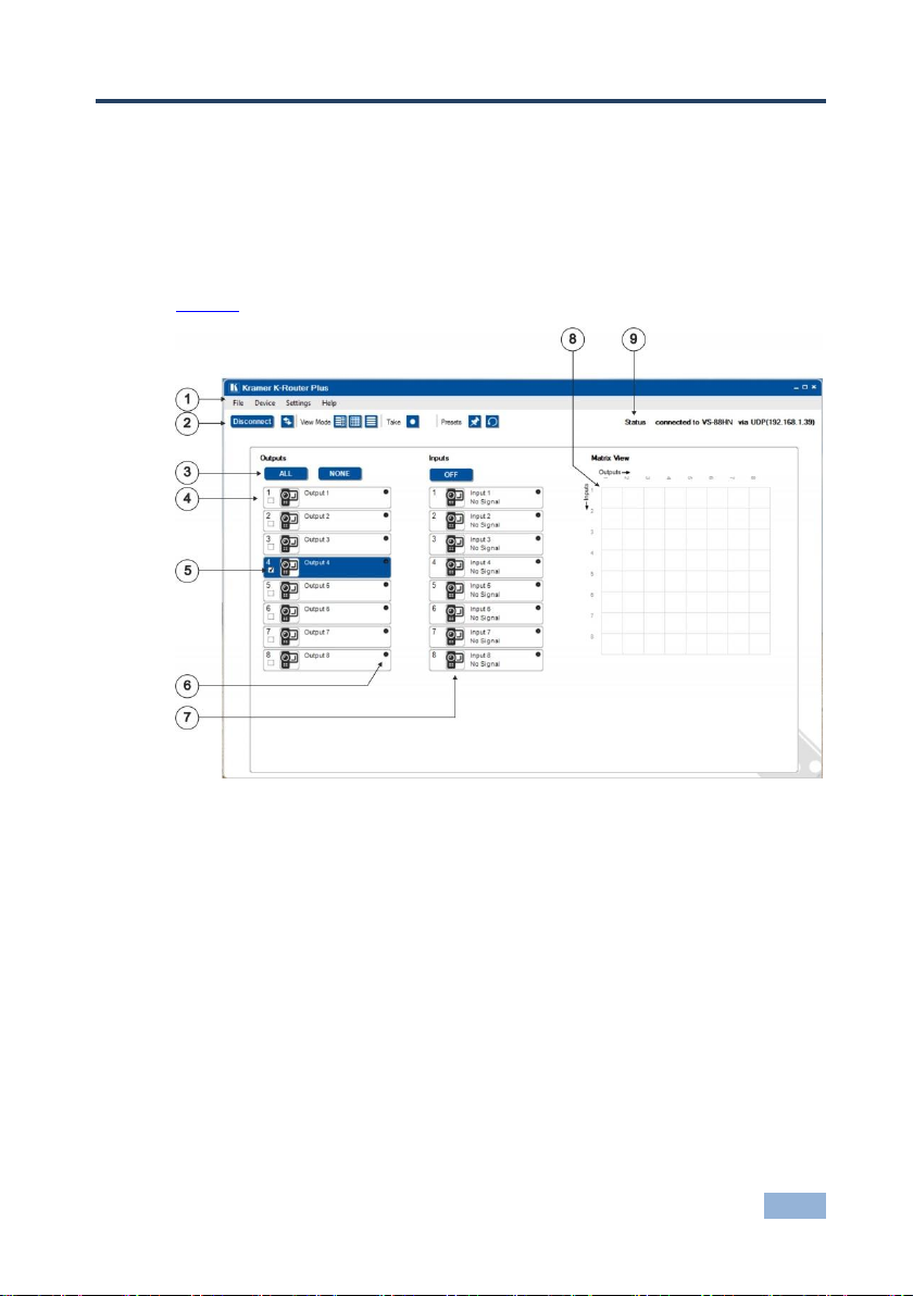
Figure 1 defines the elements of the main screen of K-Router Plus.
Figure 1: K-Router Plus Main Screen
Page 6
4
K-Router Plus Online User Guide - Defining K-Router Plus
#
Feature
Function
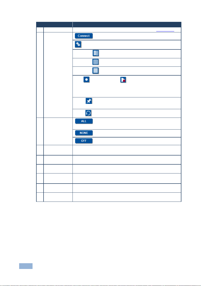
1
Menu Bar
Shows File, Device, Settings and Help submenus (see Section 3.1)
2
Tool Button Bar
Connects and disconnects a router
Refreshes all router information to the program
View Mode displays the I/O list and matrix views together
View Mode displays a matrix view only
View Mode displays the I/O list only
Take Sets up the switch, actuates the change, x cancels
the take.
Note: K-Router Plus displays the change on screen but the device does
not switch until the actuate button is pushed
Preset saves the present state to a preset memory location (in
this example 1–16, the number varies according to the machine)
Preset loads a saved state from a preset memory location
3
I/O Button Bar
Selects all outputs. Together with OFF disconnects all
inputs and outputs
Deselects all outputs
Turns off the selected input
4
OUTPUT
Buttons
Select the target output(s) (1 – n)
The number of output buttons match the configuration of your router
5
Output Check
Box
Allows choosing multiple outputs
6
Active Status
Indicator
On input and output buttons, lights red if inactive, green if active
7
INPUT Buttons
Select the target input (1 – n)
The number of input buttons match the configuration of your router
8
MATRIX VIEW
Displays all active crosspoint connections; click at an intersection to
make a new connection
9
STATUS
Indicates the type of router, its connection method and if the device is
connected or not
Page 7
K-Router Plus Online User Guide - Defining K-Router Plus
5
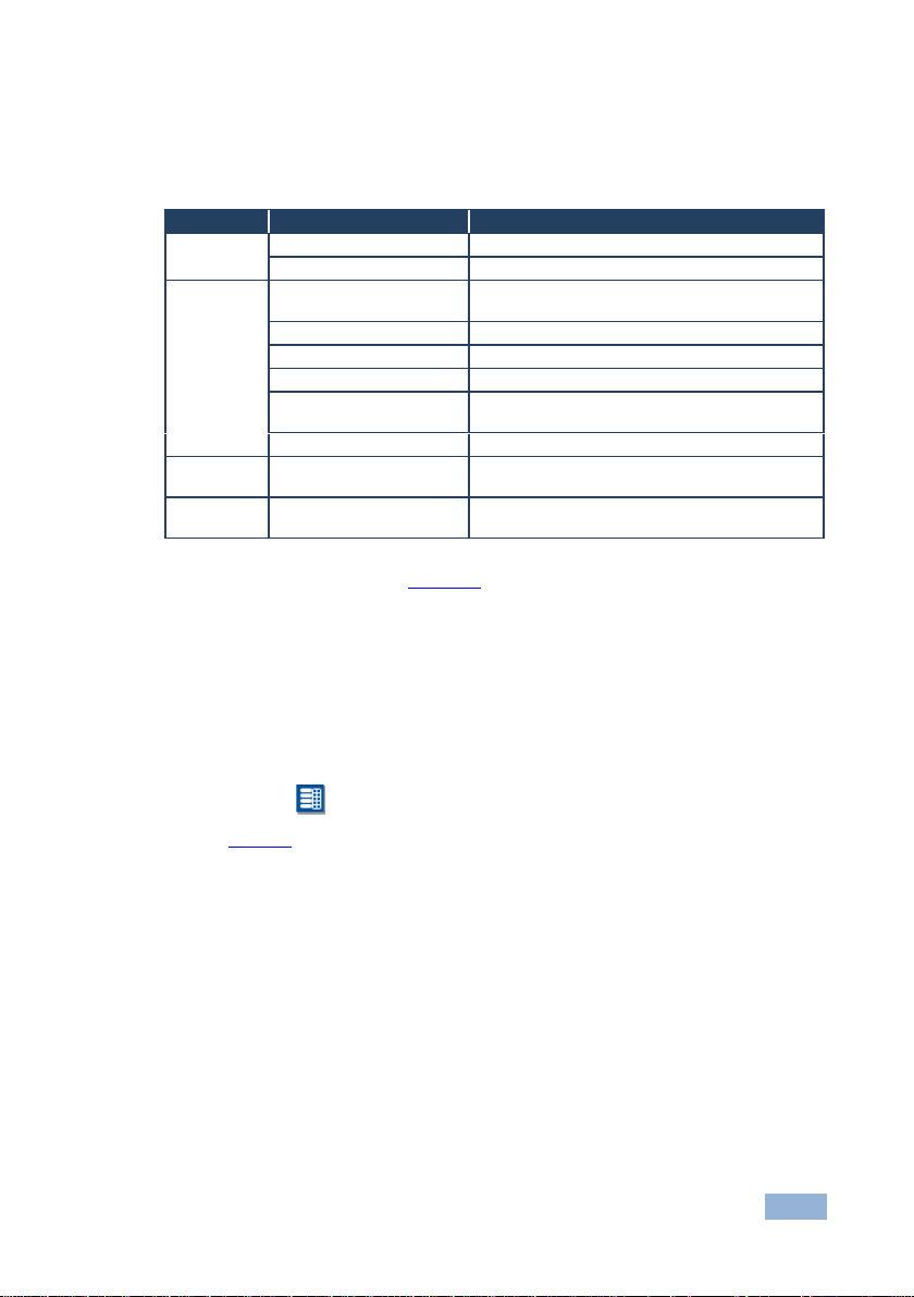
Menu
Item
Function
File
Connect/Disconnect
Connects and disconnects a router
Exit
Closes the K-Router Plus application
Device
Device Details
Displays and allows changing the router
information and communication parameters
Firmware Update
Updates the router firmware from a saved file
EDID Manager
Allows loading, viewing and saving an EDID
Restart Device
Restarts the connected router
Edit Custom Resolutions
Allows the choice and specification of nonstandard resolutions
K-Link Data
Routes K-Link data connections
Settings
System Colors
Allows the selection and customization of system
colors
Help
About
Displays the K-Router Plus software version and
Kramer contact information
3.1 Defining the Menu Bar Items
The following table explains the functions available on the menu bar.
Note: Active functions appear in black. Inactive functions appear in grey.
For detailed explanations see Section 5.
3.2 Defining the View Mode
The view mode allows you to view the connections as an I/O list, a matrix or a
combined list and matrix view.
To see the dual mode view:
Click the icon. The I/O list and a matrix display all the connections
(Figure 2).
Page 8

6
K-Router Plus Online User Guide - Defining K-Router Plus
Figure 2: Dual Mode View
To see the matrix view:
Click the icon. A large matrix displays all of the connections (Figure 3).
Figure 3: Matrix Mode View
Page 9

K-Router Plus Online User Guide - Defining K-Router Plus
7
To see the Input/Output list view:
Click the icon. Inputs and outputs are displayed as a list (Figure 4).
Figure 4: I/O List Mode View
Page 10

8
K-Router Plus Online User Guide - Using K-Router Plus
4 Using K-Router Plus
This section explains how to operate the main functions of K-Router Plus.
4.1 Connecting a Router
To connect a router:
1. Physically connect a router via RS-232, USB or a network to a PC running
K-Router Plus.
2. Click the menu item File > Connect or click the Connect button.
The Connection Method screen opens:
Figure 5: Connection Method Window
3. Choose the appropriate connection method, set the parameters as required
and click Connect.
4.2 Switching Inputs to Outputs
To switch inputs to outputs:
In the list view, click the desired output button then the desired input button
In the matrix view, click the intersection of the desired input and output
Page 11

K-Router Plus Online User Guide - Using K-Router Plus
9
4.2.1 Switching Using the I/O Buttons
The following examples show how to perform switching functions.
To switch one input to one output (in this example Input 4 to Output 4):
Click the desired output (4), then the desired input (4)
The connection appears on the Matrix View
To switch one input to several outputs (in this example Input 4 to Outputs 2, 4
and 6):
Click the check boxes on the desired outputs (2, 4, 6), then the desired
input (4)
The connections appear on the Matrix View
Page 12

10
K-Router Plus Online User Guide - Using K-Router Plus
To switch one input to all outputs (in this example Input 4 to all Outputs):
Click the ALL button (all outputs highlight), then the desired input (4)
The connections appear on the Matrix View
Page 13

K-Router Plus Online User Guide - Using K-Router Plus
11
To disconnect one connection:
Click on the desired connection and click OFF
The connection is broken and disappears from the matrix
To disconnect all connections:
Click on the ALL button and click OFF
All connections are broken and disappear from the matrix
4.2.2 Switching Using the Matrix
The matrix is useful for making individual connections quickly (either in the matrix
or dual views).
To switch one input to one output (in this example Input 3 to Output 4):
Navigate to the intersection of Input 3 and Output 4 and click
The new connection appears on the matrix in the matrix and dual views
To disconnect one connection:
Click on the desired connection and click OFF
The connection is broken and disappears from the matrix
Page 14

12
K-Router Plus Online User Guide - Using K-Router Plus
4.3 Using the Take Button
Takeallowsyoutosetupacertainconfiguration“offline”andtomakethecomplete
switch all at once.
To perform a switch using Take:
1. Click .
The button changes to . (To cancel the Take, press .)
2. Choose the output(s).
3. Choose the input.
K-Router Plus displays the new configuration in the matrix view.
4. Press
The device switches and displays the new configuration.
4.4 Using Presets
Use presets to store frequently used setups.
To save a preset (in this example, Input 3 connected to Outputs 1, 3, 5, 7 are
saved to Preset 1):
From the given setup click the button
The preset buttons drop down
Page 15

K-Router Plus Online User Guide - Using K-Router Plus
13
Click on Preset 1
The following warning appears:
To continue, click OK
The setup is saved in Preset 1
To restore a preset (in this example, Preset 1 containing Input 3 connected to
Outputs 1, 3, 5, 7):
Click the button
The preset buttons drop down
Click the desired Preset number (1)
The existing setup (if any) disconnects and the saved configuration activates
Page 16

14
K-Router Plus Online User Guide - Using K-Router Plus
Property
Values
Display
Show the display status: ON, OFF
Resolution
Choose from a list of available resolutions plus user-defined
Native Resolution
Show sink native resolution
Signal Type
Outputsignaltype(HDMI/DVI/…)
HDCP Follow Input
Show HDCP working mode
Color Space
RGB, YCbCr 4:2:2, YCbCr 4:4:4, Follow Output
Label
Text to identify the output
Icon
Choose from Kramer, camera, DVD, Laptop, Mobile, Music, PC,
Tablet
EDID
Displays the EDID associated with the port
4.5 Using Input/Output Properties
Input/output properties display and control port settings.
To display the port properties:
Right-click on an output port
The Output properties widow appears:
Right-click on an input port
The Input properties widow appears:
Page 17

K-Router Plus Online User Guide - Using K-Router Plus
15
Property
Values
Signal
Show the signal status: ON, OFF
Signal Type
Inputsignaltype(HDMI/DVI/…)
HDCP
Input signal encryption status (ON/OFF)
Color Space
RGB, YCbCr 4:2:2, YCbCr 4:4:4, Follow Output
Label
Text to identify the output
Icon
Choose from Kramer, camera, DVD, Laptop, Mobile, Music, PC,
Tablet
EDID
Displays the EDID associated with the port
Page 18

16
K-Router Plus Online User Guide - Using the Menu Utilities
5 Using the Menu Utilities
Note: Utilities may vary from device to device. Available utilities show in black text.
Unavailable utilities are greyed out.
5.1 Using Device Details
Device Details enables you to change information on the unit name and the K-Net
ID and set network communication parameters.
To change device details:
Click Device > Device Details and modify any non-greyed field as needed
When finished, click APPLY and CLOSE
Figure 6: Device Detail Window
Page 19

K-Router Plus Online User Guide - Using the Menu Utilities
17
5.2 Updating the Firmware
This utility allows you to install the latest version router firmware downloaded from
Kramer Electronics.
To upgrade the router firmware:
1. Download the latest version of firmware from the Kramer Web site to a file
on your computer.
2. Navigate to Device > Firmware Update and select.
The Firmware Update window opens.
Figure 7: Firmware Upgrade Window
3. Enter the name of the downloaded firmware file in the Select File field or
click Browse to navigate to the location of the file and select it.
4. Do not check CRC - If checked, the file is uploaded and burned to the
device. If not checked, the device compares the uploaded CRC to the
currently existing CRC and does not burn it if the same file is detected.
5. Click Upload to send the file to the router.
6. After completion, the router resets then reconnect it to K-Router Plus.
Page 20

18
K-Router Plus Online User Guide - Using the Menu Utilities
5.3 Using the EDID Manager
The EDID Manager allows you to load and view an EDID from any I/O source, file
or default and then save it to an input or file.
To use the EDID Manager:
1. Navigate to Device > EDID Manager and select.
The EDID manager window opens.
Figure 8: EDID Manager Window
In this example, the EDID from Input 1 is saved to Input 2 (see Figure 9).
2. Load the EDID source by clicking Load EDID from Input 1. Input lights
green, the Input 1 button highlights and the EDID for Input 1 displays in the
central matrix.
3. Click Save EDID to Input 2, then click Save.
Asuccessfulsaveisindicatedbyamessage“TheEDIDwascopied”.Click
OK to close.
Page 21

K-Router Plus Online User Guide - Using the Menu Utilities
19
Figure 9: Saving an EDID
To save the EDID to all inputs, click Save EDID to ALL
To deselect all target inputs, click NONE
EDIDs can be loaded or saved to files. Click File Browse and navigate to
the desired file location.
5.4 Restarting the Device
To restart the router:
1. Navigate to Device > Restart Device and click.
The Restart Device window opens.
Figure 10: Restart Device Window
2. Confirm the restart by clicking OK.
The router restarts.
3. Reconnect by selecting File > Connect or clicking Connect.
Page 22

20
K-Router Plus Online User Guide - Using the Menu Utilities
5.5 Editing Custom Resolutions
Device defined resolutions are read from/written to the device. Available
resolutions are read from/written to the computer.
To edit a resolution:
1. Navigate to Device > Edit Custom Resolutions and select.
The Edit Custom Resolutions window opens:
Figure 11: Edit Custom Resolutions Window
2. Choose the resolution source (available or device defined) by clicking the
radio button at the upper left of the panel.
.
Page 23

K-Router Plus Online User Guide - Using the Menu Utilities
21
5.6 Using K-Link Data
K-Link Data allows the user to route K-Link data connections in a manner similar to
the video matrix view. Point and click the intersection square between elements
(input, output, network, or device) to make the data connection.
To route a K-Link data connection:
Click any non-grey intersecting square.
The square turns green to indicate the connection is made.
In this example:
In 4 is connected to Out 1
In 5 is connected to Out 2
Local 2 is connected to RS-232
Figure 12: K-Link Data Window
Note: Grey squares are forbidden connections. Only one connection is allowed per
device. Making a second connection to a device breaks the previous connection.
Page 24

22
K-Router Plus Online User Guide - Using the Menu Utilities
5.7 Using the Settings Menu
To change system colors:
1. Navigate to Settings > System Colors and select.
The System Colors window opens.
Figure 13: System Colors Window
2. To change a color, click on the desired left-hand color box.
The Select Color window opens.
Figure 14: Select Color Window
3. Click on the desired color to select. The selected color and its number code
appear in the upper-left corner.
Page 25

K-Router Plus Online User Guide - Using the Menu Utilities
23
5.8 Using the Help Menu
To see the version of the K-Router Plus software and Kramer contact
information, select Help > About.
Figure 15: About Window
 Loading...