

Page 1

KRAMER ELECTRONIC S LTD.
USER MANUAL
MODEL:
VP-4 x1 CS
4x1 PC Graphics Clean
Switcher
P/N: 2900-300198 Re v 4
Page 2
Page 3

VP-4x1CS - Contents
i
Contents
1 Introduction 1
2 Getting Started 2
2.1 Achieving the Best Performance 2
2.2 Safety Instructions 2
2.3 Recycling Kramer Products 3
3 Overview 4
4 Defining the VP-4x1CS 4x1 PC Graphics Clean Switcher 5
4.1 Using the IR Transmitter 7
5 Installing in a Rack 8
6 Connecting the VP-4x1CS 4x1 PC Graphics Clean Switcher 9
6.1 Connecting the Remote Selector and Mute Switches 10
6.2 Connecting a Balanced/Unbalanced Stereo Audio Output 11
6.3 Connecting to the VP-4x1CS via RS-232 11
6.4 Connecting to the VP-4x1CS via Ethernet 11
6.5 Ethernet Port Configuration 13
7 Operating the VP-4x1CS 4x1 PC Graphics Clean Switcher 14
7.1 Operating the VP-4x1CS Locally 14
7.2 Operating the VP-4x1CS Remotely Using the Embedded Web Pages 16
7.3 Using the K-Single Application 23
8 Wiring the TP RJ-45 Ethernet Connector 24
9 Technical Specifications 25
10 Default Communication Parameters 26
11 Kramer Protocol 2000 27
11.1 Protocol 2000 Hex Codes 29
12 Protocol 3000 31
12.1 Kramer Protocol 3000 Syntax 31
12.2 Kramer Protocol 3000 Commands 34
Figures
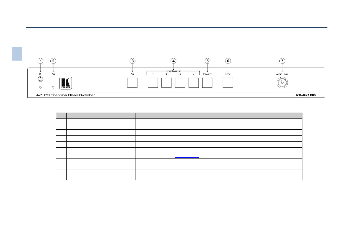
Figure 1: VP-4x1CS 4x1 PC Graphics Clean Switcher Front Panel 5
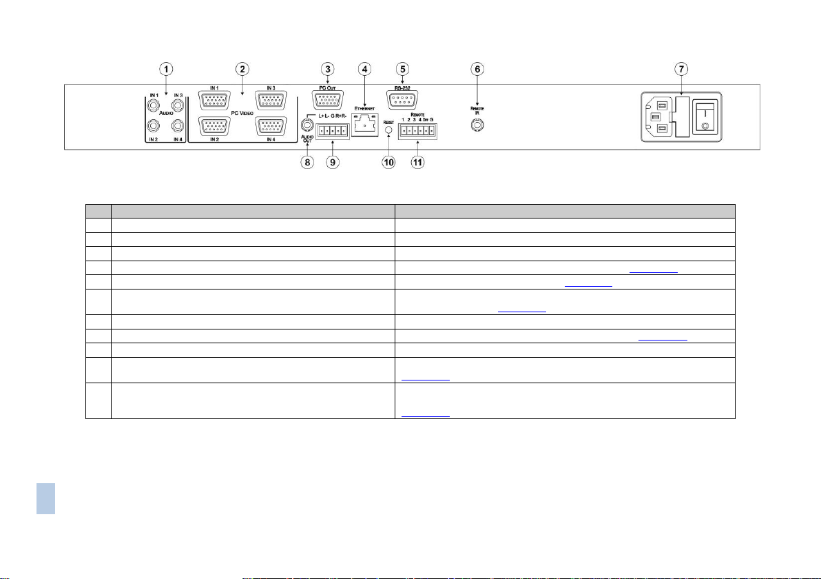
Figure 2: VP-4x1CS 4x1 PC Graphics Clean Switcher Rear Panel 6
Figure 3: Connecting the VP-4x1CS 4x1 PC Graphics Clean Switcher 9
Figure 4: Remote Selector and Output Mute Switch Connection 10
Figure 5: Balanced Stereo Audio Connection 11
Figure 6: Unbalanced Stereo Audio Connection 11
Figure 7: Local Area Connection Properties Window 12
Figure 8: Internet Protocol (TCP/IP) Properties Window 13
Figure 9: Java Test Page Success Message 17
Figure 10: The Loading Page 18
Figure 11: First Time Security Warning 18
Figure 12: VP-4x1CS Switching Matrix Page 19
Figure 13: Switching an Input to an Output 20
Figure 14: Exiting Offline Warning 21
Figure 15: Audio Gain Page 21
Figure 16: Configurations Page 22
Figure 17: TP Pinout Wiring 24
Page 4

VP-4x1CS - Introduction
1
1 Introduction
Welcome to Kramer Electronics! Since 1981, Kramer Electronics has been
providing a world of unique, creative, and affordable solutions to the vast range of
problems that confront video, audio, presentation, and broadcasting professionals
on a daily basis. In recent years, we have redesigned and upgraded most of our
line, making the best even better!
Our 1,000-plus different models now appear in 11 groups that are clearly defined
by function: GROUP 1: Distribution Amplifiers; GROUP 2: Switchers and Routers;
GROUP 3: Control Systems; GROUP 4: Format/Standards Converters; GROUP 5:
Range Extenders and Repeaters; GROUP 6: Specialty AV Products; GROUP 7:
Scan Converters and Scalers; GROUP 8: Cables and Connectors; GROUP 9:
Room Connectivity; GROUP 10: Accessories and Rack Adapters and GROUP 11:
Sierra Video Products.
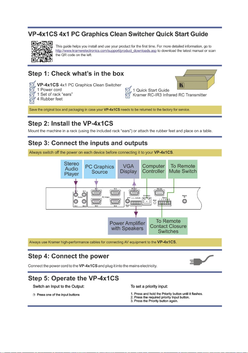
Congratulations on purchasing your Kramer VP-4x1CS 4x1 PC Graphics Clean
Switcher, which is ideal for the following typical applications:
Display systems requiring simple input selection
Remote monitoring of computer activity in schools and businesses
Rental/staging applications
Multimedia and presentation source selection
Page 5

2
VP-4x1CS - Getting Started
Go to http://www.kramerelectronics.com/support/product_downloads.asp
to check for up-to-date user manuals, application programs, and to check if
firmware upgrades are available (where appropriate).
This equipment is to be used only inside a building. It may only be
connected to other equipment that is installed inside a building.
Caution:
There are no operator serviceable parts inside the unit
Warning:
Use only the power cord that is supplied with the unit
Warning:
Do not open the unit. High voltages can cause
electrical shock! Servicing by qualified personnel only
Warning:
Disconnect the power and unplug the unit from the wall
before installing
i
!
!
2 Getting Started
We recommend that you:
Unpack the equipment carefully and save the original box and packaging
materials for possible future shipment
Review the contents of this user manual
2.1 Achieving the Best Performance
To achieve the best performance:
Use only good quality connection cables (we recommend Kramer high-
performance, high-resolution cables) to avoid interference, deterioration in
signal quality due to poor matching, and elevated noise levels (often
associated with low quality cables)
Do not secure the cables in tight bundles or roll the slack into tight coils
Avoid interference from neighboring electrical appliances that may adversely
influence signal quality
Position your VP-4x1CS away from moisture, excessive sunlight and dust
2.2 Safety Instructions
Page 6

VP-4x1CS - Getting Started
3
2.3 Recycling Kramer Products
The Waste Electrical and Electronic Equipment (WEEE) Directive 2002/96/EC
aims to reduce the amount of WEEE sent for disposal to landfill or incineration by
requiring it to be collected and recycled. To comply with the WEEE Directive,
Kramer Electronics has made arrangements with the European Advanced
Recycling Network (EARN) and will cover any costs of treatment, recycling and
recovery of waste Kramer Electronics branded equipment on arrival at the EARN
facility. For details of Kramer’s recycling arrangements in your particular country
go to our recycling pages at http://www.kramerelectronics.com/support/recycling/.
Page 7

4
VP-4x1CS - Overview
3 Overview
The VP-4x1CS is a high quality 4x1 switcher for PC graphics (up to UXGA) and
audio signals. Kramer’s Kr-isp® technology ensures high quality video.
In particular, the VP-4x1CS features:
Clean switching
Automatic switching
Kramer’s innovative integrated sync processing; Kr-isp® technology provides
a sharp, stable image by restoring the signal waveform even when the sync
level is too low
Audio-follow-video switching
Remote, contact closure input selection
Remote, contact closure output muting
A lock button to prevent unwanted tampering with the buttons on the front
panel
Independent audio level adjustment
Support for Kramer Protocol 2000 and Protocol 3000
You can control the VP-4x1CS using the front panel buttons, or remotely via:
RS-232 serial commands transmitted by a PC, touch screen system or other
serial controller
The Kramer RC-IR3 infrared remote control transmitter
A PC connected to the Ethernet port on the device via a LAN
An optional external remote IR receiver (see Section 4.1)
Remote, contact closure switches for input selection and muting
Page 8
#
Feature
Function
1
IR Receiver and LED
Signal receiver and LED for the infrared remote control transmitter. The indicator LED
lights yellow when receiving an IR signal
2
ON LED
The LED lights green when the device is powered on
3
OFF Button
Press to mute the output
4
INPUT SELECTOR 1~4 Buttons
Press one of the 4 input buttons to switch it to the output
5
PRIORITY Button
Press to set the current active input as the priority input. Press again to cancel priority
input selection (see Section 7.1.1)
6
LOCK Button
Press and hold to lock the front panel buttons. Press and hold again to unlock the
buttons (see Section 7.1.3)
7
AUDIO LEVEL Control
Rotate clockwise to increase the audio level and anticlockwise to decrease the audio
level of the audio output
5
VP-4x1CS
– Defining the
VP-4x1CS PC Graphics Clean
Switcher
4 Defining the VP-4x1CS 4x1 PC Graphics Clean Switcher
This section defines the front and rear panels of the VP-4x1CS.
Figure 1: VP-4x1CS 4x1 PC Graphics Clean Switcher Front Panel
Page 9
VP-4x1CS
– Defining the V
P-4x1CS PC Graphics Clean
Switcher
6
#
Feature
Function
1
AUDIO IN1~IN4 Unbalanced Stereo Audio 3.5mm Mini Jacks
Connect to up to 4 unbalanced, stereo audio sources
2
PC VIDEO IN1~IN4 UXGA 15-pin HD Connectors (F)
Connect to up to 4 PC graphics sources
3
PC OUT UXGA 15-pin HD Connector (F)
Connect to the PC graphics acceptor
4
ETHERNET RJ-45 Connector
Connect to a PC via a LAN to control the device (see Section 6.4)
5
RS-232 Serial Port 9-pin D-sub Connector (F)
Connect to a PC/serial controller (see Section 6.3)
6
REMOTE IR Opening
Connect to an external IR receiver for controlling the device using an IR
remote controller (see Section 4.1)
7
Mains Power Connector, Fuse and Power Switch
Plug in the power cord and switch the device on and off
8
AUDIO OUT Unbalanced Stereo Audio 3.5mm Mini Jack
Connect to the unbalanced, stereo audio acceptor (see Section 6.2)
9
AUDIO OUT Balanced Stereo Audio 5-pin Terminal Block
Connect to the balanced, stereo audio acceptor
10
RESET Button
Press and hold while powering on to reset the device to factory default (see
Section 4.1)
11
REMOTE Contact Closure Selector and Mute Switches 6-way
Terminal Block
Connect pins 1 to 4 and G to up to 4 remote, input selector, contact closure
switches. Connect the OFF and G pins to a remote mute switch (see
Section 6.1)
Figure 2: VP-4x1CS 4x1 PC Graphics Clean Switcher Rear Panel
Page 10

VP-4x1CS - Defining the VP-4x1CS 4x1 PC Graphics Clean Switcher
7
4.1 Using the IR Transmitter
You can use the RC-IR3 IR transmitter to control the machine via the built-in IR
receiver on the front panel or, instead, via an optional external IR receiver (for
example, P/N C-A35M/IRR-50). The external IR receiver can be located up to 15m
away from the machine. This distance can be extended to up to 60m when used
with three extension cables (for example, P/N C-A35M/A35F-50).
Before using the external IR receiver, be sure to arrange for your Kramer dealer to
insert the internal IR connection cable (for example, P/N: 505-70434010-S) with
the 3.5mm connector that fits into the REMOTE IR opening on the rear panel.
Connect the external IRreceiver to the REMOTE IR 3.5mm connector.
Page 11
8
VP-4x1CS - Installing in a Rack
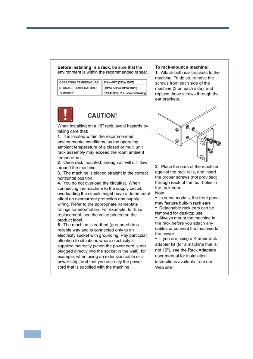
5 Installing in a Rack
This section provides instructions for rack mounting the unit.
Page 12
VP-4x1CS - Connecting the VP-4x1CS 4x1 PC Graphics Clean Switcher
9
Always switch off the power to each device before connecting it to your
VP-4x1CS. After connecting your VP-4x1CS, connect its power and
then switch on the power to each device.
i
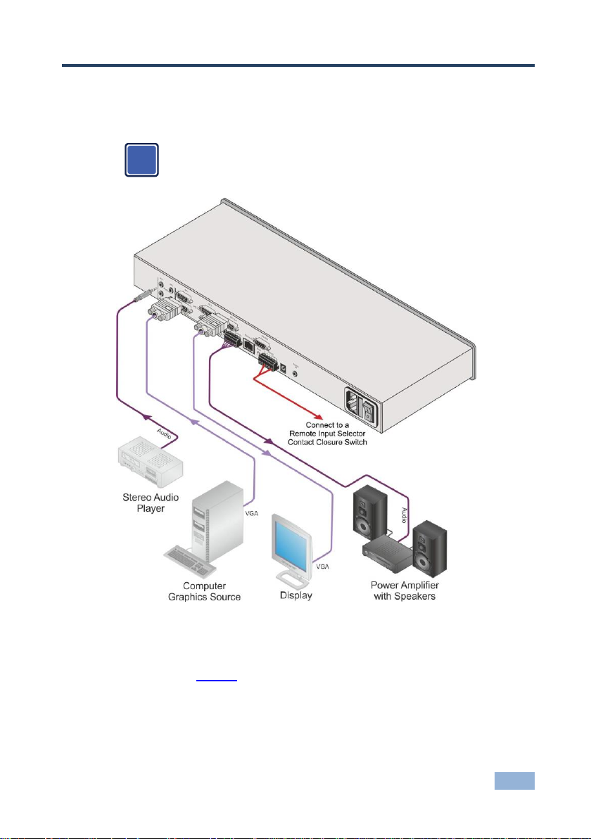
6 Connecting the VP-4x1CS 4x1 PC Graphics
Clean Switcher
Figure 3: Connecting the VP-4x1CS 4x1 PC Graphics Clean Switcher
To connect the VP-4x1CS 4x1 PC Graphics Clean Switcher as illustrated in
the example in Figure 3:
1. Connect up to four audio sources (for example, stereo audio players) to the
Audio In connectors.
2. Connect up to four PC graphics sources to the PC Video In connectors.
Page 13

10
VP-4x1CS - Connecting the VP-4x1CS 4x1 PC Graphics Clean Switcher
3. Connect the PC Out connector to the PC graphics acceptor (for example, a
display).
4. Connect the Audio Out 5-pin terminal block to the balanced, stereo, audio
acceptor.
5. Connect the Remote 6-pin terminal block (pins 1, 2, 3, 4, and G) to up to four
remote, contact closure, input selector switches.
6. Connect the Remote 6-pin terminal block (pins Off and G) to a remote,
contact closure, mute switch.
7. If required, connect a PC/controller to the RS-232 port (see Section 7.1.2)
and/or the Ethernet port (see Section 6.4).
8. Connect the device to the mains electricity (not shown in Figure 3) and
power the device on.
6.1 Connecting the Remote Selector and Mute Switches
You can connect:
Up to four remote switches to enable remote input selection and,
A remote output mute switch
The contact closure, remote selector pins operate in a similar way to the Input
Selector buttons.
Figure 4 illustrates how to connect remote, momentary-contact switches.
Figure 4: Remote Selector and Output Mute Switch Connection
Page 14

VP-4x1CS - Connecting the VP-4x1CS 4x1 PC Graphics Clean Switcher
11
Figure 5: Balanced Stereo
Audio Connection
Figure 6: Unbalanced Stereo
Audio Connection
In Figure 4, the operation of Switches 1 and 4 select Inputs 1 and 4 respectively;
operation of Switch A mutes the output.
Note: Do not connect more than one terminal to ground at a time.
6.2 Connecting a Balanced/Unbalanced Stereo Audio Output
Figure 5 illustrates how to wire a balanced, stereo, audio output connection.
Figure 6 illustrates how to wire an unbalanced, stereo, audio output connection.
6.3 Connecting to the VP-4x1CS via RS-232
You can connect to the VP-4x1CS via an RS-232 connection using, for example, a
PC. Note that a null-modem adapter/connection is not required.
To connect to the VP-4x1CS via RS-232:
Connect the RS-232 9-pin D-sub rear panel port on the VP-4x1CS unit via a
9-wire straight cable (only pin 2 to pin 2, pin 3 to pin 3, and pin 5 to pin 5
need to be connected) to the RS-232 9-pin D-sub port on your PC
6.4 Connecting to the VP-4x1CS via Ethernet
You can connect the VP-4x1CS via the Ethernet, using a crossover cable (see
Section 6.4.1) for direct connection to the PC or a straight through cable (see
Section 6.4.2) for connection via a network hub or network router.
After connecting the Ethernet port, you have to install and configure your Ethernet Port. For
detailed instructions, see the “Ethernet Configuration (FC-11) guide.pdf” file in the technical
support section at http://www.kramerelectronics.com.
Page 15

12
VP-4x1CS - Connecting the VP-4x1CS 4x1 PC Graphics Clean Switcher
This type of connection is recommended for identification of the factory
default IP Address of the VP-4x1CS during the initial configuration
i
6.4.1 Connecting the Ethernet Port Directly to a PC
You can connect the Ethernet port of the VP-4x1CS to the Ethernet port on your
PC via a crossover cable with RJ-45 connectors.
After connecting the Ethernet port, configure your PC as follows:
1. On your desktop, right-click the My Network Places icon.
2. Select Properties.
3. Right-click Local Area Connection Properties.
4. Select Properties.
The Local Area Connection Properties window appears.
5. Select the Internet Protocol (TCP/IP) and click the Properties Button (see
Figure 7).
Figure 7: Local Area Connection Properties Window
Page 16

VP-4x1CS - Connecting the VP-4x1CS 4x1 PC Graphics Clean Switcher
13
6. Select Use the following IP Address, and fill in the details as shown in
Figure 8. You can use any IP address in the range 192.168.1.1 to
192.168.1.255 (excluding 192.168.1.39) that is provided by your IT
department.
7. Click OK.
Figure 8: Internet Protocol (TCP/IP) Properties Window
6.4.2 Connecting the Ethernet Port via a Network Hub
You can connect the Ethernet port of the VP-4x1CS to the Ethernet port on a
network hub or network router, via a straight through cable with RJ-45 connectors.
6.5 Ethernet Port Configuration
To configure the Ethernet port, use either the embedded Web pages (see
Section 7.2.7) or the K-Upload Software which is available for download from
http://www/kramerelectronics.com.
Page 17

14
VP-4x1CS - Operating the VP-4x1CS 4x1 PC Graphics Clean Switcher
7 Operating the VP-4x1CS 4x1 PC Graphics
Clean Switcher
The VP-4x1CS can be operated:
Locally using the front panel buttons (see Section 7.1)
Remotely using:
The embedded Web pages (see Section 7.2)
The K-Single Application (see Section 7.3)
7.1 Operating the VP-4x1CS Locally
This section describes:
Setting a priority Input (see Section 7.1.1)
Switching Between Protocol 2000 and Protocol 3000 (see Section 7.1.2)
Locking and unlocking the front panel buttons (see Section 7.1.3)
Resetting the device to factory default settings (see Section 7.1.4)
Upgrading the VP-4x1CS firmware (see Section 7.1.5)
EDID Handling (see Section 7.1.6)
7.1.1 Setting a Priority Input
When a priority input is set, the VP-4x1CS cycles through the inputs from 1 to 4
(beginning with the priority input) looking for a live signal. If there is no signal on
the priority input the device cycles through the inputs (from low to high) and
selects the first input that is encountered with a live signal.
Note: When a priority Input is selected, the device does not perform clean
switching.
Note: For clean switching, all extracted sources must be of the same resolution.
Page 18

VP-4x1CS - Operating the VP-4x1CS 4x1 PC Graphics Clean Switcher
15
To set a priority Input:
1. Press and hold the Priority button for a few seconds.
The button flashes.
2. Press the required priority Input button.
The selected Input button flashes.
3. Press the Priority button to save the selection.
The selected Input is made the priority input. Both the Priority and the
selected Priority Input buttons light.
Note: When a priority input is selected it is still possible to manually select an
input; both LEDs remain lit.
To cancel the priority Input selection:
Press the lit Priority button.
The priority Input is cancelled and the Priority button no longer lights
7.1.2 Switching Between Protocol 2000 and Protocol 3000
To switch between Protocol 2000 and Protocol 3000 using the front panel
buttons:
1. Press INPUT SELECTOR buttons 1 and 3 at the same time.
Protocol 3000 is active.
2. Press INPUT SELECTOR buttons 1 and 2 at the same time.
Protocol 2000 is active.
7.1.3 Locking and unlocking the Front Panel Buttons
To lock and unlock the front panel buttons:
1. Press and hold the unlit Lock button.
The front panel buttons are locked and the button LED lights.
2. Press and hold the lit Lock button.
The front panel buttons are unlocked and the button LED no longer lights.
Page 19

16
VP-4x1CS - Operating the VP-4x1CS 4x1 PC Graphics Clean Switcher
7.1.4 Resetting the Device to Factory Default Configuration
To reset the device to the factory default configuration:
1. Turn the device off.
2. Press and hold the Reset button on the rear panel of the device.
3. While holding the button depressed, turn the device on.
4. Hold the button depressed for a few seconds and release the button.
The configuration is reset to the factory default.
7.1.5 Upgrading the Firmware
For instructions on upgrading the firmware refer to the “K-Upload” Guide (go to
http://www.kramerelectronics.com/support/product_downloads.asp).
7.1.6 EDID Handling
The monitor EDID is read and automatically written to all four inputs. When the
monitor is changed, the EDID automatically updates. When there is no device
connected to the output, the VP-4x1CS sends the EDID that was read from the
last device connected to the output.
7.2 Operating the VP-4x1CS Remotely Using the Embedded Web Pages
You can use a Web browser to operate the VP-4x1CS using the embedded Web
pages.
The embedded Web pages can be used to remotely operate the VP-4x1CS using
a Web browser and an Ethernet connection.
Before attempting to connect:
Perform the procedures in Section 6.4
Ensure that the Java™ software is installed and functioning correctly on your
computer. If not, download it from www.java.com
Page 20

VP-4x1CS - Operating the VP-4x1CS 4x1 PC Graphics Clean Switcher
17
Ensure that your browser is supported—Microsoft IE (V6.0 and higher),
Google Chrome, Firefox (V3.0 and higher)
To check that Java is installed and running correctly, browse to
http://www.java.com/en/download/help/testvm.xml
This page runs a test and displays a Java success (see Figure 9) or failure
message.
Figure 9: Java Test Page Success Message
If you do not see the success message, follow the instructions on the page to:
Load and enable Java
Enable Javascript in your browser
7.2.1 To Log On to the VP-4x1CS Web Pages
To log on to VP-4x1CS Web pages:
1. Open your Internet browser.
2. Type the unit’s IP number in the Address bar of your browser.
The Loading page appears.
Note: Opening the VP-4x1CS Web Page automatically switches the device to
Protocol 3000.
Page 21

18
VP-4x1CS - Operating the VP-4x1CS 4x1 PC Graphics Clean Switcher
Figure 10: The Loading Page
The first time that you run the program, the Warning-Security screen appears.
Figure 11: First Time Security Warning
Page 22

VP-4x1CS - Operating the VP-4x1CS 4x1 PC Graphics Clean Switcher
19
3. Click Run.
The main switching control Home page is displayed which shows a graphical
interpretation of the front panel (see Figure 12).
The Web pages let you control the VP-4x1CS via the Ethernet. The menu appears
on the left side of the screen. There are three remote operation Web pages:
The switching matrix (see Section 7.2.2)
Audio gain (See Section 7.2.5)
Configuration (See Section 7.2.7)
A description of each Web page is displayed if you place your mouse over the
question mark that appears on the left side of the screen.
7.2.2 The Switching Matrix Page
The VP-4x1CS switching matrix page lets you route any of the four inputs to the
output by clicking the relevant square on the matrix.
Figure 12: VP-4x1CS Switching Matrix Page
From this page you can:
Select an input by clicking on the matrix (see Section 7.2.3)
Operate in the At-Once or Confirm mode (see Section 7.2.4)
Lock and unlock the front panel buttons (see Section 7.2.5)
Page 23

20
VP-4x1CS - Operating the VP-4x1CS 4x1 PC Graphics Clean Switcher
7.2.3 Switching an Input to the Output
To switch an input to the output (for example, input 3 to output 1):
Click on the required switching point within the matrix (In 3 to Out 1, see
Figure 13).
The blue square moves to the In 3 to Out 1 switching matrix box, indicating
that In 3 is now switched to Out 1.
Figure 13: Switching an Input to an Output
7.2.4 Operating in the Confirm Mode
By default, the device is set to the At-Once mode.
To operate in the Confirm mode:
1. Click the red Offline button.
The border of the button turns dark.
2. Click the desired Input in the switching matrix.
The blue square indicator appears as an outline on the matrix and the Take
and Cancel buttons turn blue.
3. Click either Take to accept the changes or Cancel to abandon the changes.
4. Click the Online button to exit the Confirm mode.
If you click the Online button before you click the Take button, the warning
shown in Figure 14 appears.
Page 24

VP-4x1CS - Operating the VP-4x1CS 4x1 PC Graphics Clean Switcher
21
Figure 14: Exiting Offline Warning
5. Click OK to cancel all changes made. Click Cancel to return to the
switching matrix screen with the changes made but not saved.
7.2.5 Locking and Unlocking the Front Panel Buttons
To lock and unlock the front panel buttons:
1. Click on the unlocked icon .
The front panel buttons are locked and the locked icon appears .
2. Click on the locked icon.
The front panel buttons are unlocked and the unlocked button appears.
7.2.6 The Audio Gain Page
The Audio Gain screen lets you set the gain for the four inputs and the output.
Figure 15: Audio Gain Page
To change an input or output gain:
1. Using the Input Gain drop-down list, select the channel number.
2. Click and hold the + or – button to increase or decrease the gain
respectively.
Page 25

22
VP-4x1CS - Operating the VP-4x1CS 4x1 PC Graphics Clean Switcher
7.2.7 The Configurations Page
The Configurations page lets you view some Ethernet settings and change others
(see Figure 16). Fields with a white background are editable; fields with a blue
background are read-only.
Figure 16: Configurations Page
To change the configuration definitions:
1. Modify the values as required.
2. Click the blue Submit button to apply changes or Cancel to abandon them.
A confirmation message appears asking if you are sure you want to change
the network settings.
3. Click Yes.
A message appears informing you that the configuration has been
successfully changed.
4. Click OK.
5. If the IP address has been changed, close your browser and reload the Web
page using the new IP address.
Page 26

VP-4x1CS - Operating the VP-4x1CS 4x1 PC Graphics Clean Switcher
23
7.3 Using the K-Single Application
The K-Single Application can be used to operate the VP-4x1CS. Download it
from http://www.kramerelectronics.com/support/product_downloads.asp.
Note: As the K-Single Application will only work with Protocol 2000 so you must
switch the VP-4x1CS to Protocol 2000 either from the front panel (see section
7.1.2) or from the Communication menu of the K-Single Application.
Page 27

24
VP-4x1CS - Wiring the TP RJ-45 Ethernet Connector
EIA /TIA 568B
Figure 17: TP Pinout Wiring
PIN
Wire Color
1
Orange / White
2
Orange
3
Green / White
4
Blue 5 Blue / White
6
Green
7
Brown / White
8
Brown
8 Wiring the TP RJ-45 Ethernet Connector
This section defines the TP pinout using a straight pin-to-pin cable with RJ-45
connectors.
Page 28

VP-4x1CS - Technical Specifications
25
INPUTS:
4 PC graphics on 15-pin HD (F) connectors
4 Unbalanced stereo audio on 3.5mm mini jack
connectors
OUTPUTS:
1 PC graphics on a 15-pin HD (F) connectors
1 Balanced stereo audio on a 5-pin terminal block
1 Unbalanced stereo audio on a 3.5mm mini jack
VIDEO BANDWIDTH:
Up to UXGA (including WUXGA)
VIDEO COUPLING:
DC
COLOR PHASE:
0 deg
VIDEO INPUT IMPEDANCE:
75Ω
VIDEO OUTPUT IMPEDANCE:
75Ω
VIDEO S/N RATIO:
>–52dB @5MHz unweighted
VIDEO ISOLATION/CROSSTALK:
<–54dB @5MHz unweighted
AUDIO COUPLING:
AC
AUDIO INPUT IMPEDANCE:
100kΩ
AUDIO OUTPUT IMPEDANCE:
150Ω
DC OFFSET:
40mV
AUDIO BANDWIDTH:
21kHz @–3dB
AUDIO SIGNAL/NOISE RATIO:
86dB @1kHz A weighted
THD + NOISE:
0.008% @1kHz A weighted
AUDIO CROSSTALK:
–72dB @1kHz
POWER CONSUMPTION:
100240V AC, 50/60Hz, 23VA
CONTROLS:
Front panel buttons, infrared remote control
transmitter, RS-232, Ethernet, Audio level, Remote
contact closure input selector switches, Remote
contact closure mute switch
OPERATING TEMPERATURE:
0° to +40°C (32° to 104°F)
STORAGE TEMPERATURE:
–40° to +70°C (–40° to 158°F)
HUMIDITY:
10% to 90%, RHL non-condensing
DIMENSIONS:
19” x 7.28” x 1U (W, D, H)
WEIGHT:
1.7kg (3.74lbs) approx.
ACCESSORIES:
Power cord, IR transmitter, rack ”ears”
OPTIONS:
External remote IR receiver cable
Specifications are subject to change without notice at http://www.kramerelectronics.com
9 Technical Specifications
Page 29

26
VP-4x1CS - Default Communication Parameters
RS-232
Protocol 2000
Protocol 3000 (Default)
Baud Rate:
9600
Baud Rate:
115,200
Data Bits:
8
Data Bits:
8
Stop Bits:
1
Stop Bits:
1
Parity:
None
Parity:
None
Command Format:
HEX
Command Format:
ASCII
Example (Output 1 to Input 1):
0x01, 0x81,
0x81, 0x81
Example (Output 1 to Input 1):
#AV
1>1<CR>
Switching Protocol
P2000 -> P3000
P3000 -> P2000
Command:
0x38, 0x80, 0x83, 0x81
Command:
#P2000<CR>
Front
Panel:
Press and hold Output 1 and
Output 3 simultaneously
Front Panel:
Press and hold Output 1 and
Output 2 simultaneously
Ethernet
Default Settings
Reset Settings
IP Address: 192.168.1.39
Power cycle the unit while holding in the
Factory Reset button, located on the rear
panel of the unit.
TCP Port #: 5000
UDP Port #: 50000
10 Default Communication Parameters
Page 30

VP-4x1CS - Kramer Protocol 2000
27
MSB
LSB
DESTINATION
INSTRUCTION
0 D N5
N4
N3
N2
N1
N0
7 6 5 4 3 2 1
0
1st byte
INPUT
1
I6
I5
I4
I3
I2
I1
I0 7 6 5 4 3 2 1 0
2nd byte
OUTPUT
1
O6
O5
O4
O3
O2
O1
O0
7 6 5 4 3 2 1
0
3rd byte
MACHINE NUMBER
1
OVR X M4
M3
M2
M1
M0 7 6 5 4 3 2 1 0
4th byte
11 Kramer Protocol 2000
The Kramer Protocol 2000 RS-232/RS-485 communication uses four bytes of
information as defined below. All the values in the table are decimal, unless
otherwise stated.
1st BYTE: Bit 7 – Defined as 0.
D – “DESTINATION”: 0 - for sending information to the switchers (from the PC);
1 - for sending to the PC (from the switcher).
N5…N0 – “INSTRUCTION”
The function that is to be performed by the switcher(s) is defined by the INSTRUCTION (6 bits). Similarly, if a function is
performed via the machine’s keyboard, then these bits are set with the INSTRUCTION NO., which was performed. The
instruction codes are defined according to the table below (INSTRUCTION NO. is the value to be set for N5…N0).
2nd BYTE: Bit 7 – Defined as 1.
I6…I0 – “INPUT”.
When switching (ie. instruction codes 1 and 2), the INPUT (7 bits) is set as the input number which is to be switched.
Similarly, if switching is done via the machine’s front-panel, then these bits are set with the INPUT NUMBER which was
switched. For other operations, these bits are defined according to the table.
3rd BYTE: Bit 7 – Defined as 1.
O6…O0 – “OUTPUT”.
When switching (ie. instruction codes 1 and 2), the OUTPUT (7 bits) is set as the output number which is to be switched.
Similarly, if switching is done via the machine’s front-panel, then these bits are set with the OUTPUT NUMBER which
was switched. For other operations, these bits are defined according to the table.
4th BYTE: Bit 7 – Defined as 1.
Bit 5 – Don’t care.
OVR – Machine number override.
M4…M0 – MACHINE NUMBER.
Used to address machines in a system via their device numbers. When several machines are controlled from a single
serial port, they are usually configured together with each machine having an individual machine number. If the OVR bit
is set, then all machine numbers accept (implement) the command, and the addressed machine replies. For a single
machine controlled via the serial port, always set M4…M0 = 1, and make sure that the machine itself is configured as
MACHINE NUMBER = 1.
Page 31

28
VP-4x1CS - Kramer Protocol 2000
Instruction Codes for Protocol 2000
Instruction
Definition for Specific Instruction
Notes
#
Description
Input
Output
0
RESET VIDEO
0 0 1
1
SWITCH VIDEO
Set equal to video input that is
switched
(0 = disconnect)
Set equal to video output that
is switched
(0 = to all the outputs)
2, 15
5
REQUEST STATUS
OF A VIDEO OUTPUT
Set as SETUP #
Equal to output number
whose status is required
4, 3
15
REQUEST WHETHER
SETUP IS DEFINED /
VALID INPUT IS
DETECTED
SETUP #
or
Input #
or
Output #
0 – For checking if setup is
defined
1 – For checking if input is
valid
2 – For checking if output is
valid
3 – For checking if EDID
output is valid
8
16
ERROR / BUSY
For invalid / valid input (i.e.
OUTPUT byte = 4 or OUTPUT
byte = 5),
this byte is set as the input #;
For invalid / valid output (i.e.
OUTPUT byte=7 or OUTPUT
byte=8), this byte is set as the
output#
0 – Error
1 – Invalid instruction
2 – Out of range
3 – Machine busy
4 – Invalid input
5 – Valid input
6 – RX buffer overflow
7 – Invalid output
8 – Valid output
9 – Valid EDID
9, 25
30
LOCK FRONT PANEL
0 – Unlock panel
1 – Lock panel
0
2
31
REQUEST WHETHER
PANEL IS LOCKED
0 0 16
61
IDENTIFY MACHINE
1 – Video machine name
2 – Audio machine name
3 – Video software version
4 – Audio software version
5 – RS-422 controller name
6 – RS-422 controller version
7 – Remote control name
8 – Remote software version
9 – Protocol 2000 revision
10 – Control data machine name
11 – Control data software
version
For names:
0 – Request first 4 digits
1 – Request first suffix
2 – Request second suffix
3 – Request third suffix
10 – Request first prefix
11 – Request second prefix
12 – Request third prefix
For versions:
0 – Main board
or the number of external
board
13
62
DEFINE MACHINE
1 – Number of inputs
2 – Number of outputs
3 – Number of setups
1 – For video
2 – For audio
3 – For SDI
4 – For remote panel
5 – For RS-422 controller
6 – For control data
14
Notes on the above table:
NOTE 1 - When the master switcher is reset, (e.g. when it is turned on), the reset code is sent to the PC. If this code is
sent to the switchers, it resets according to the present power-down settings.
NOTE 2 - These are bi-directional definitions. That is, if the switcher receives the code, it performs the instruction; and if
the instruction is performed (due to a keystroke operation on the front panel), then these codes are sent. For example, if
the HEX code:
01 85 88 83
was sent from the PC, then the switcher (machine 3) switches input 5 to output 8. If the user switched input 1 to output 7
via the front panel keypad, then the switcher sends HEX codes:
41 81 87 83
to the PC.
When the PC sends one of the commands in this group to the switcher, then, if the instruction is valid, the switcher
replies by sending to the PC the same four bytes that it was sent (except for the first byte, where the DESTINATION bit
is set high).
NOTE 3 - SETUP # 0 is the present setting. SETUP # 1 and higher are the settings saved in the switcher's memory, (i.e.
those used for Store and Recall).
Page 32

VP-4x1CS - Kramer Protocol 2000
29
Video
Audio
IN 1
, , ,
2, , ,
IN 2
, 2, ,
2, 2, ,
IN 3
, 3, ,
2, 3, ,
IN 4
, 4, ,
2, 4, ,
IN 1
IN 2
IN 3
IN 4
Increase
18 81 86 81
18 82 86 81
18 83 86 81
18 84 86 81
Decrease
18 81 87 81
18 82 87 81
18 83 87 81
18 84 87 81
NOTE 4 - The reply to a "REQUEST" instruction is as follows: the same instruction and INPUT codes as were sent are
returned, and the OUTPUT is assigned the value of the requested parameter. The replies to instructions 10 and 11 are
as per the definitions in instructions 7 and 8 respectively. For example, if the present status of machine number 5 is
breakaway setting, then the reply to the HEX code:
0B 80 80 85
would be HEX codes
4B 80 81 85
NOTE 8 - The reply is as in TYPE 3 above, except that here the OUTPUT is assigned with the value 0 if the setup is not
defined / no valid input is detected; or 1 if it is defined / valid input is detected.
NOTE 13 - This is a request to identify the switcher/s in the system. If the OUTPUT is set as 0, and the INPUT is set as
1, 2, 5 or 7, the machine sends its name. The reply is the decimal value of the INPUT and OUTPUT. For example, for a
2216, the reply to the request to send the audio machine name would be (HEX codes):
7D 96 90 81 (i.e. 128dec+ 22dec for 2nd byte, and 128dec+ 16dec for 3rd byte).
If the request for identification is sent with the INPUT set as 3 or 4, the appropriate machine sends its software version
number. Again, the reply would be the decimal value of the INPUT and OUTPUT - the INPUT representing the number
in front of the decimal point, and the OUTPUT representing the number after it. For example, for version 3.5, the reply to
the request to send the version number would be (HEX codes):
7D 83 85 81 (i.e. 128dec+ 3dec for 2nd byte, 128dec+ 5dec for 3rd byte).
If the OUTPUT is set as 1, then the ASCII coding of the lettering following the machine’s name is sent. For example, for
the VS-7588YC, the reply to the request to send the first suffix would be (HEX codes):
7D D9 C3 81 (i.e. 128dec+ ASCII for “Y”; 128dec+ ASCII for “C”).
NOTE 14 - The number of inputs and outputs refers to the specific machine which is being addressed, not to the system.
For example, if six 16X16 matrices are configured to make a 48X32 system (48 inputs, 32 outputs), the reply to the HEX
code:
3E 82 81 82 (ie. request the number of outputs)
would be HEX codes:
7E 82 90 82
ie. 16 outputs
NOTE 15 – When the OVR bit (4th byte) is set, then the “video” commands have universal meaning. For example,
instruction 1 (SWITCH VIDEO) causes all units (including audio, data, etc.) to switch. Similarly, if a machine is in
“FOLLOW” mode, it performs any “video” instruction.
NOTE 16 - The reply to the “REQUEST WHETHER PANEL IS LOCKED” is as in NOTE 4 above, except that here the
OUTPUT is assigned with the value 0 if the panel is unlocked, or 1 if it is locked.
11.1 Protocol 2000 Hex Codes
The following table lists the hex values to switch an input to the output for a single
VP-4x1CS device.
The following table lists the hex codes that increase or decrease audio input gain.
The following table lists the hex codes that set the audio input gain.
Page 33

30
VP-4x1CS - Kramer Protocol 2000
IN 1
IN 2
IN 3
IN 4
Level [Rel]
16 81 80* 81
16 82 80* 81
16 83 80* 81
16 84 80* 81
-63dB Mute
… … …
…
16 81 8D* 81
16 82 8D* 81
16 83 8D* 81
16 84 8D* 81
-50dB
… … …
…
16 81 BF* 81
16 82 BF* 81
16 83 BF* 81
16 84 BF* 81
0dB
… … …
…
16 81 C6* 81
16 82 C6* 81
16 83 C6* 81
16 84 C6* 81
+7dB (Max)
OUT 1
OUT 2
OUT 3
OUT 4
Increase
18 81 80 81
18 82 80 81
18 83 80 81
18 84 80 81
Decrease
18 81 81 81
18 82 81 81
18 83 81 81
18 84 81 81
OUT 1
Level [Rel]
16 81 80* 81
-30dB
…
16 81 9E* 81
0dB
…
16 81 B2* 81
+20dB
Note: Before sending any of these codes, the command 2A 86 80 81 must be
sent.
* BYTE 3 = 0x80 + Gain Value (0x00-0x46)
The following table lists the hex codes that increase or decrease the audio output
gain.
The following table lists the hex codes that set the audio output gain.
Note: Before sending any of these codes, the command 2A 87 80 81 must be
sent.
*BYTE 3 = 0x80 + Gain Value (0x00-0x32)
Page 34

VP-4x1CS - Protocol 3000
31
Start
Address (optional)
Body
Delimiter
#
Destination_id@
Message
CR
Start
Body
Delimiter
#
Command SP Parameter_1,Parameter_2,…
CR
Start
Address
Body
Delimiter
#
Destination_id@
Command_1 Parameter1_1,Parameter1_2,…|
Command_2 Parameter2_1,Parameter2_2,…|
Command_3 Parameter3_1,Parameter3_2,…|…
CR
Start
Address (optional)
Body
delimiter
~
Sender_id@
Message
CR LF
Start
Address (optional)
Body
Delimiter
~
Sender_id@
Command SP [Param1 ,Param2 …] result
CR LF
12 Protocol 3000
The VP-4x1CS can be operated using serial commands from a PC, remote
controller or touch screen using the Kramer Protocol 3000.
This section describes:
Kramer Protocol 3000 syntax (see Section 12.1)
Kramer Protocol 3000 commands (see Section 12.2)
12.1 Kramer Protocol 3000 Syntax
12.1.1 Host Message Format
12.1.1.1 Simple Command
Command string with only one command without addressing:
12.1.1.2 Command String
Formal syntax with commands concatenation and addressing:
12.1.2 Device Message Format
12.1.2.1 Device Long Response
Echoing command:
CR = Carriage return (ASCII 13 = 0x0D)
LF = Line feed (ASCII 10 = 0x0A)
SP = Space (ASCII 32 = 0x20)
Page 35

32
VP-4x1CS - Protocol 3000
12.1.3 Command Terms
Command
A sequence of ASCII letters ('A'-'Z', 'a'-'z' and '-').
Command and parameters must be separated by at least one space.
Parameters
A sequence of alphanumeric ASCII characters ('0'-'9','A'-'Z','a'-'z' and some special
characters for specific commands). Parameters are separated by commas.
Message string
Every command entered as part of a message string begins with a message
starting character and ends with a message closing character.
Note: A string can contain more than one command. Commands are separated by
a pipe ( '|' ) character.
Message starting character
'#' – For host command/query
'~' – For device response
Device address (Optional, for K-NET)
K-NET Device ID followed by '@'
Query sign
'?' follows some commands to define a query request.
Message closing character
CR – For host messages; carriage return (ASCII 13)
CRLF – For device messages; carriage return (ASCII 13) + line-feed (ASCII 10)
Command chain separator character
When a message string contains more than one command, a pipe ( '|' ) character
separates each command.
Spaces between parameters or command terms are ignored.
Page 36

VP-4x1CS - Protocol 3000
33
12.1.4 Entering Commands
You can directly enter all commands using a terminal with ASCII communications
software, such as HyperTerminal, Hercules, etc. Connect the terminal to the serial
or Ethernet port on the Kramer device. To enter CR press the Enter key.
( LF is also sent but is ignored by command parser).
For commands sent from some non-Kramer controllers like Crestron, some
characters require special coding (such as, /X##). Refer to the controller manual.
12.1.5 Command Forms
Some commands have short name syntax in addition to long name syntax to allow
faster typing. The response is always in long syntax.
12.1.6 Chaining Commands
Multiple commands can be chained in the same string. Each command is
delimited by a pipe character (“|”). When chaining commands, enter the message
starting character and the message closing character only once at the
beginning of the string and at the end.
Commands in the string do not execute until the closing character is entered.
A separate response is sent for every command in the chain.
12.1.7 Maximum String Length
64 characters
Page 37

34
VP-4x1CS - Protocol 3000
Command
Short
Form
Description
Permission
# Protocol handshaking
End User
ADL Set audio level in specific amplifier stage
ADL? Read audio volume level
AUD-LVL
ADL
Set audio level in specific amplifier stage
AUD-LVL?
ADL?
Read audio volume level
AV Switch audio and video
BUILD-DATE?
Read device build date
End User
ETH-PORT
ETHP
Change protocol Ethernet port
ETH-PORT?
ETHP?
Read protocol Ethernet port
FACTORY
Reset to factory default configuration
INFO-IO?
Read in/out count
End User
INFO-PRST?
Read maximum preset count
End User
LOCK-FP
LCK
Lock front panel
Administrator
LOCK-FP?
LCK?
Read Lock front panel
End User
MODEL?
Read device model
End User
NET-DHCP
NTDH
Set DHCP mode
NET-DHCP?
NTDH?
Read subnet mask
NET-GATE
NTGT
Set gateway address
NET-GATE?
NTGT?
Read subnet mask
NET-IP
NTIP
Set IP address
NET-IP?
NTIP?
Read IP address
NET-MAC?
NTMC
Read MAC address
NET-MASK
NTMSK
Set subnet mask
NET-MASK?
NTMSK?
Read subnet mask
P2000
Switch to Protocol 2000
End User
P3000
Switch to Protocol 3000
End User
PRIO Set switching priority
End User
PRIO?
Get switching priority
End User
PROT-VER?
Read device protocol version
End User
RESET
Reset device
Administrator
SIGNAL?
Get valid/invalid status
End User
SN? Read device serial number
End User
VERSION?
Read device firmware version
End User
VID Switch Video only
End User
VID? Get Video switch state
End User
VOL Set simple audio volume
VOL? Read simple audio level
VOLUM
VOL
Set simple audio volume
VOLUM?
VOL?
Read simple audio level
12.2 Kramer Protocol 3000 Commands
Page 38

Page 39

For the latest information on our products and a list of Kramer
distributors, visit our Web site where updates to this user
manual may be found.
We welcome your questions, comments, and feedback.
Web site: www.kramerelectronics.com
E-mail: info@kramerel.com
P/N:
2900-300198
Rev:
4
!
SAFETY WARNIN G
Disconnect the unit from the power
supply before opening and servicing
 Loading...