

Page 1

Kramer Electronics, Ltd.
USER MANUAL
Model:
VP-419xl
Video To SXGA/HD Scaler
Page 2

Contents
Contents
1
Introduction 1
2
Getting Started 1
2.1 Quick Start 1
3
Overview 3
4
Your VP-419xl Video to SXGA/HD Scaler 4
5
Connecting the VP-419xl Video to SXGA/HD Scaler 6
6
Controlling the VP-419xl 8
6.1 Controlling via the Front Panel Buttons 8
6.2 Using the CONTROL Buttons 8
6.2.1 The MAIN MENU 8
6.2.2 The PICTURE Menu 9
6.2.3 The SETUP Menu 9
6.3 Controlling via the Infra-Red Remote Control Transmitter 10
7
Technical Specifications 11
Figures
Figure 1: VP-419xl Video To SXGA/HD Scaler – Front and Rear View 4
Figure 2: Connecting the VP-419xl Video To SXGA/HD Scaler 7
Figure 3: Infra-Red Remote Control Transmitter 10
Tables
Table 1: VP-419xl Video To SXGA/HD Scaler Front Panel Features 5
Table 2: VP-419xl Video To SXGA/HD Scaler Rear Panel Features 5
Table 3: HD15 PINOUT for HD 6
Table 4: The MAIN MENU Features 8
Table 5: The PICTURE Menu Features 9
Table 6: The SETUP Menu Features 9
Table 7: Infra-Red Remote Control Transmitter Functions 10
Table 8: Technical Specifications of the VP-419xl Video To SXGA/HD Scaler 11
i
Page 3

Introduction
1 Introduction
Welcome to Kramer Electronics (since 1981): a world of unique, creative and
affordable solutions to the infinite range of problems that confront the video,
audio and presentation professional on a daily basis. In recent years, we have
redesigned and upgraded most of our line, making the best even better! Our
500-plus different models now appear in 8 Groups1, which are clearly defined
by function.
Congratulations on purchasing your Kramer VP-419xl Video To SXGA/HD
Scaler. This product is ideal for:
Projection systems in conference rooms, boardrooms, hotels and churches
Home theater up-scaling
The package includes the following items:
VP-419xl Video To SXGA/HD Scaler
Power adapter (12V DC input)
Infra red remote control transmitter
This user manual2
2 Getting Started
We recommend that you:
Unpack the equipment carefully and save the original box and packaging
materials for possible future shipment
Review the contents of this user manual
Use Kramer high performance high resolution cables3
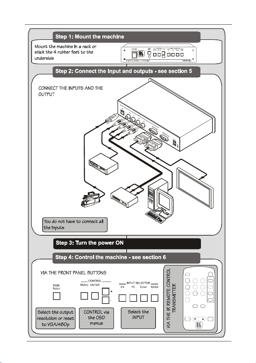
2.1 Quick Start
This Quick start chart summarizes the basic setup and operation steps.
1 GROUP 1: Distribution Amplifiers; GROUP 2: Video and Audio Switchers, Matrix Switchers and Controllers; GROUP 3:
Video, Audio, VGA/XGA Processors; GROUP 4: Interfaces and Sync Processors; GROUP 5: Twisted Pair Interfaces;
GROUP 6: Accessories and Rack Adapters; GROUP 7: Scan Converters and Scalers; and GROUP 8: Cables and Connectors
2 Download up-to-date Kramer user manuals from the Internet at this URL: http://www.kramerelectronics.com
3 The complete list of Kramer cables is on our Web site at http://www.kramerelectronics.com
1
Page 4
Plasma
Display
Computer Gra phics
DVD Player
Composite
Video Player
MENU
YPbCr
S-VIDEO
C-VIDEO
DISPLAY
PICTURE
Getting Started
s-Video
Camcorder
Source
POWER
VGA XGA
SVGA
ASPECT
480p
SXGA
576p
1080i
720p
PC
NR
3D
RESET
ENTER
2
KRAMER: SIMPLE CREATIVE TECHNOLOGY
Page 5

Overview
3 Overview
The Kramer VP-419xl Video To SXGA/HD Scaler is a high quality converter
for up-scaling composite video, s-Video (YC), and SD component video to
XGA1 and HD resolutions. It also has a computer graphics (XGA) input,
which – when selected, or when the machine is not powered - is routed
directly (bypassed) to the output. Video inputs are de-interlaced and scaled to
the selected PC or HDTV resolutions, as follows:
VGA (640x480) SXGA (1280x1024) 720p
SVGA (800x600) 480p 1080i
XGA (1024x768) 576p
The VP-419xl Video To SXGA/HD Scaler also features:
Automatic detection of NTSC, PAL-B, PAL-G, PAL-I, PAL-D, and
SECAM video standards
An On-Screen Display (OSD) for easy setup and adjustment, accessible
via the IR remote control and via the front-panel buttons
A high-performance adaptive 3D comb filter (for precise color
management)
Per-pixel motion compensated de-interlacing for artifact-free video images
Automatic detection for 3:2 pulldown for 24fps film source material
Frame rate conversion of 50Hz to 60Hz for PAL input signals
A Vertical Temporal (VT) Filter for removing jagged artifacts
Advanced color/luminance transient improvement circuitry
A PC Input connector for easy integration into an existing system
A built-in procamp for convenient signal adjustment
A non-volatile memory that retains the last settings used
The machine is fed from an external 12V DC source, making it suitable for
field operation.
Control your VP-419xl:
Directly, via the front panel push buttons
Remotely, from the infra-red remote control transmitter
1 The terminology XGA is used throughout this manual, where this implies any RGBHV signal on an HD15 connector
having a resolution from VGA up to SXGA
3
Page 6

Your VP-419xl Video to SXGA/HD Scaler
To achieve the best performance:
Connect only good quality connection cables, thus avoiding interference,
deterioration in signal quality due to poor matching, and elevated noiselevels (often associated with low quality cables)
Avoid interference from neighboring electrical appliances and position
your Kramer VP-419xl away from moisture, excessive sunlight and dust
Caution – No operator-serviceable parts inside unit.
Warning – Use only the Kramer Electronics input power
wall adapter that is provided with this unit1.
Warning – Disconnect power and unplug unit from wall
before installing or removing device or servicing unit.
4 Your VP-419xl Video to SXGA/HD Scaler
Figure 1, Table 1 and Table 2 define the VP-419xl Video To SXGA/HD Scaler:
Figure 1: VP-419xl Video To SXGA/HD Scaler – Front and Rear View
1 For example: model number AD2512C, part number 2535-000251
4
KRAMER: SIMPLE CREATIVE TECHNOLOGY
Page 7

Your VP-419xl Video to SXGA/HD Scaler
Table 1: VP-419xl Video To SXGA/HD Scaler Front Panel Features
# Feature Function
1 POWER Switch Switch for turning the unit ON or OFF
2 RGB/RESET Button Illuminates when the output resolution is set to RGB. Press to set output
3 IR Receiver Lights when receiving signals from the remote control transmitter
4 MENU Button Displays the OSD menu (see section 6.2)
5 ENTER Button Press to accept changes and change the SETUP parameters (see
6 + Button Press to go up the menu list or adjust the PICTURE submenu values
CONTROL
7
8 CV Button Press to select the composite video source
9 YC Button Press to select the s-Video (YC) video source
10 COMP. Button Press to select the component video source
11
- Button Press to go down the menu list or adjust the PICTURE submenu values
INPUT
SXGA Button Press to select the SXGA source
SELECTOR
to Y Pb Pr (the button no longer illuminates). Press and hold for more
than 3 seconds to reset to VGA. Press and hold for 10 seconds to reset
to 480p
section 6.2.3)
(see section 6.2.2)
(see section 6.2.2)
Table 2: VP-419xl Video To SXGA/HD Scaler Rear Panel Features
# Feature Function
12 YC 4p Connector Connects to the s-Video source
13 CV RCA Connector Connects to the composite video source
14 Y RCA Connector
15 CB RCA Connector Connects to the interlaced1 component video source2
INPUTS
16 CR RCA Connector
17
18 SXGA / HD OUT HD15 Connector Connects to the SXGA or HDTV (component video)
19 12 VDC +12V DC connector for powering the unit
SXGA PASS HD15 Connector Connects to the VGA/Y, Pb, Pr source3
acceptor
1 Not compatible with progressive scan Y, Pb, Pr or HDTV
2 For component video, connect all three connectors: Y, Cb, Cr (also known as YUV)
3 This PC input signal is not scaled, but is available for pass-through when the PC source is selected
5
Page 8

Connecting the VP-419xl Video to SXGA/HD Scaler
5 Connecting the VP-419xl Video to SXGA/HD Scaler
Connect1 your VP-419xl, as illustrated in the example in Figure 2:
1. Connect an s-Video source (for example, an s-Video camcorder) to the
YC INPUT 4p connector.
2. Connect a composite video source (for example, a composite video player)
to the CV INPUT RCA connector.
3. Connect a component video source (for example, a DVD player) to the Y,
Cb and Cr INPUT RCA connectors.
4. Connect an SXGA graphics source to the SXGA PASS INPUT HD15
connector2.
5. Connect the SXGA/HD OUT HD15 connector to a video acceptor (for
example, a plasma display) as follows:
When connecting to an XGA acceptor (RGBHV), then connect to the
acceptor’s XGA connector
When connecting to a component acceptor (Y, Cb, Cr), then connect
as shown in Table 3
Table 3: HD15 PINOUT for HD3
PIN # Signal
1 Cr
2 Y
3 Cb
6. Connect the 12V DC power adapter to the power socket and connect the
adapter to the mains electricity (not shown in Figure 2).
1 You do not have to connect all the inputs, connect only those that are required
2 This PC input signal is not scaled, but is available for pass-through when the PC Source is selected
3 The PINOUT should be: PIN 1 = Cr, PIN 2 = Y and PIN 3 = Cb (with pins 6, 7 and 8 as ground respectively)
6
KRAMER: SIMPLE CREATIVE TECHNOLOGY
Page 9

Connecting the VP-419xl Video to SXGA/HD Scaler
Plasma
Display
Computer Graphics
Source
DVD Player
Composite
Video Player
s-Video
Camcorder
Figure 2: Connecting the VP-419xl Video To SXGA/HD Scaler
7
Page 10

Controlling the VP-419xl
6 Controlling the VP-419xl
The VP-419xl can be controlled directly via the front panel buttons (see section
6.1), via the OSD menu (see section 6.2), and/or remotely from the infra-red
remote control transmitter (see section 6.3).
6.1 Controlling via the Front Panel Buttons
The VP-419xl includes the following control front panel buttons:
An RGB/RESET button for setting the output to either RGB or Y, Pb, Pr
or resetting1 the resolution to VGA or 480p
CONTROL buttons, including the MENU, ENTER, + and – buttons
INPUT SELECTOR buttons for selecting the required input (CV, YC,
COMP. or SXGA)
6.2 Using the CONTROL Buttons
The CONTROL buttons let you control the VP-419xl via the OSD menu
Press the MENU button to enter the menu2
Press the ENTER button to accept changes and to change the menu
settings
Press the + and – buttons to move through the OSD menu, which is
displayed on the video output, or adjust the PICTURE parameters
On the OSD menu, select EXIT to exit the menu.
6.2.1 The MAIN MENU
Table 4 defines the MAIN MENU features and functions.
Table 4: The MAIN MENU Features
Mode Function
PICTURE Set the picture parameters (contrast, brightness, color, hue, detail and reset), see
SOURCE Select the desired input source: video, s-Video, Y, CB, CR or computer
RESOLUTION After selecting the output type3, select between the RGB output resolutions (VGA,
SETUP Select the aspect, output, 3D enhance, digital NR, display and HV output (see section
INFORMATION Displays the source, resolution and software version
EXIT Select to exit the menu
1 Press for 3 seconds to reset to VGA and press for 10 seconds to reset to 480p
2 The menu times out after 8 seconds
3 By pressing the RGB/RESET button or via the OSD menu
8
section 6.2.2
SVGA, XGA or SXGA) or the YPbPr output resolutions (480p, 576p, 720p or 1080i)
6.2.3)
KRAMER: SIMPLE CREATIVE TECHNOLOGY
Page 11

Controlling the VP-419xl
6.2.2 The PICTURE Menu
Table 5 defines the PICTURE menu.
Table 5: The PICTURE Menu Features
Parameter Function Range Default
CONTRAST Adjust the contrast From 0 to 63 58
BRIGHT Adjust the brightness From 0 to 63 31
COLOR Adjust the color From 0 to 63 31
HUE Adjust the hue From 0 to 63 31
DETAIL Adjust the sharpness From 0 to 63 10
RESET Select RESET and press ENTER to reset to the default parameters
EXIT Select to exit to the MAIN MENU
6.2.3 The SETUP Menu
Table 6 defines the SETUP menu.
Table 6: The SETUP Menu Features
Parameter Function
ASPECT1 Select between STANDARD, 4:3 and 16:9
OUTPUT Select a PC (RGB) output or an HDTV (Y, Pb, Pr) output
3D ENHANCE Turn the 3D comb filter function ON or OFF2
DIGITAL NR Turn the digital noise reduction function ON or OFF
DISPLAY Set to ON to display the input standard and the output resolution on the screen all the time
HV OUTPUT Select ON to send H and V synchronization when Y, Pb, Pr is selected for the output3
EXIT Select to exit to the MAIN MENU
Set to INFO to briefly display the input standard and the output resolution on the screen
after a change is made
Otherwise, set to OFF
1 STANDARD will output the signal in the same aspect ratio as the input aspect ratio. 4:3 and 16:9 will always output as 4:3
and 16:9 respectively, regardless of the input aspect ratio
2 When a video player or a non-standard video source is connected to the input, the output picture may jitter. If this occurs,
turn the 3D Comb Filter to OFF
3 H and V are always sent when RGB is selected at the output
9
Page 12

Controlling the VP-419xl
MENU
YPbCr
S-VIDEO
C-VIDEO
6.3 Controlling via the Infra-Red Remote Control Transmitter
You can control the VP-419xl from the infra-red remote control transmitter,
as Figure 3 and Table 7 define:
VGA XGA
SXGA
576p 720p 1080i
PICTURE
RESET
SVGA
ASPECT
3D
480p
PC
NR
ENTER
Table 7: Infra-Red Remote Control
Transmitter Functions
Keys Function
POWER Turn power ON or OFF
DISPLAY Turn input standard and output
C-VIDEO Select the composite video input
S-VIDEO Select the s-Video input
YCbCr Select the component video input
PC Select the input PC to loop-through
VGA Set the output resolution to 640x480
SVGA Set the output resolution to 800x600
XGA Set the output resolution to 1024x768
SXGA Set the output resolution to 1280x1024
480p Set the output resolution to 852x480p
576p Set the output resolution to 852x576p
720p Set the output resolution to 1280x720p
1080i Set the output resolution to 1920x1080i
ASPECT Select the standard, normal (4:3) or the
PICTURE
RESET
3D Turn the 3D enhance feature ON or
NR Turn the digital noise reduction feature
MENU Enter the OSD menu
ENTER Press to accept changes and to
resolution information display ON or
OFF
wide (16:9) aspect ratio
Press and hold for 2 seconds to reset
all the ProcAmp settings (contrast,
brightness and so on)1
OFF
ON or OFF
change SETUP parameters
Figure 3: Infra-Red Remote Control
Transmitter
Press to adjust the picture parameters
1 In some versions, you need to be within the PICTURE menu to do this
10
KRAMER: SIMPLE CREATIVE TECHNOLOGY
Page 13

Technical Specifications
7 Technical Specifications
Table 8: Technical Specifications1 of the VP-419xl Video To SXGA/HD Scaler
INPUTS: 1 VGA/SVGA/XGA/SXGA on an HD15F connector
OUTPUT: 1 RGB/YPbPr on an HD15F connector
OUTPUT RESOLUTIONS2: VGA (640x480), SVGA (800x600), XGA (1024x768), SXGA
PROCESSING DELAY: 2 frames
CONTROLS: Front panel buttons and infra red remote for menu driven OSD control
ADDITIONAL CONTROLS: Contrast, brightness, color, tint and sharpness; Resolution, output
POWER SOURCE: 12V DC, 350mA
DIMENSIONS: 21.5cm x 16.3cm x 4.36cm (8.46” x 6.4” x 1.7”) W, D, H
WEIGHT:
ACCESSORIES: Power supply, IR remote control
OPTIONS 19" rack adapter RK-80, RK-80N
1 composite video on an RCA connector
1 component video (Y, Cb, Cr) on RCA connectors
1 s-Video on a 4p connector
(1280x1024), HDTV: 480p, 576p, 720p, 1080i
image scaling, output mode, 3D comb filter function and aspect ratio
0.66kg (1.45lbs.) approx.
1 Specifications are subject to change without notice
2 All resolutions are outputted @ 60Hz, except 576p which is outputted @ 50Hz
11
Page 14

Kramer Electronics (hereafter ) warrants this product free from defects in material and workmanship under the
The lia bility of Kramer for any effective products is limited to the repair or replacement of the product at our option. Kramer shall
Except as below, this warranty covers all defects in material or workmanship in this produc t. The following are not cove red
uncertain as to whether a dealer is authorized, please contact Kramer at one of the agents listed in the Web site
LIMI TED WARR ANTY
following terms.
HOW LONG IS THE WARRA NTY
Labor and parts are warranted for seven years from the date of the first customer purchase.
WHO IS PROTECT ED?
Only the first purchase customer may enforce this warranty.
WHAT IS COVERED AND WHAT IS NOT COVERED
Kramer
by the wa rranty:
1. Any product which is not distributed by Kramer, or which is not purchased from an authorized Kramer dealer. If you are
www.kramerelectronics.com.
2. Any product, on which the serial number has been defaced, modified or removed.
3. Damage, deterioration or malfunction resulting from:
i) Accident, misuse, abuse, neglect, fire, water, lightning or other acts of nature
ii) Product modification, or failure to follow instructions supplied with the product
iii) Repair or attempted repair by anyone not authorized by Kramer
iv) Any shipment of the product (claims must be presented to the carrier)
v) Removal or installation of the product
vi) Any other cause, which does not relate to a product defect
vii) Cartons, equipment enclosures, cables or accessories used in conjunction with the product
WHAT WE WILL PAY FOR AN D WHAT WE WILL NOT PAY F OR
We will pay labor and material expenses for covered items. We will not pay for the following:
1. Removal or installations charges.
2. Costs of initial technical adjustments (set-up), including adjustment of user controls or programming. These costs are the
responsibility of the Kramer dealer fro m whom the product was purchased.
3. Shipping charges.
HOW YOU CAN G ET WAR RANTY SERVICE
1. To obtain service on you product, you must take or ship it prepaid to any authorized Kramer service center.
2. Whenever warranty service is required, the original dated invoice (or a copy) must be presented as proof of warranty
coverage, and should be included in any shipment of the product. Please also include in any mailing a contact name,
company, address, and a description of the problem(s).
3. For the name of the nearest Kramer authorized service center, consult your authorized dealer.
LIMI TATION OF IM PLIED WARRAN TIES
All implied warranties, including warranties of merchantability and fitness for a particular purpose, are limited in duration to
the length of this warranty.
EXCLUSIO N O F DAMAGES
not be liable for:
1. Damage to other property caused by defects in this product, damages based upon inconvenience, loss of use of the product, loss
of time, commercial loss; or:
2. Any other damages, whether incidental, consequential or otherwise. Some countries may not allow limitations on how long an
implied warranty lasts and/or do not al low the exclusion or limitation of incidental or consequential damages, so the above
limitations and exclusions may not apply to you.
This warranty gives you specific legal rights, and you may also have other rights, which vary from place to place.
All products returned to Kramer for service must have prior approval. This may be obtained from your dealer.
NOTE:
This equipment has been tested to d etermine compliance with the requirements of:
EN-50081: "Electromagnetic compatibility (EMC);
Residential, commercial and light industry"
EN-50082: "Electromagnetic compatibility (EMC) generic immunity standard.
CFR-47: FCC Rules and Re gulations:
CAUT ION!
generic emission standard.
Part 1:
Part 1: Residential, commercial and light industry environment".
Part 15: “Radio frequency devices
Subpart B Unintentional radiators”
Servicing the machines can only be done by an authorized Kramer technician. Any user who makes changes or
modifications to the unit without the expressed approval of the manufacturer will void user authority to operate the
equipment.
Use the supplied DC power supply to feed power to the machine.
Please use recommended interconnection cables to connect the machine to other components.
12
KRAMER: SIMPLE CREATIVE TECHNOLOGY
Page 15

For the latest information on our products and a list of Kramer
distributors, visit our Web site: www.kramerelectronics.com,
where updates to this user manual may be found.
We welcome your questions, comments and feedback.
Safety Warning:
Disconnect the unit from the power supply before
opening/servicing.
Caution
Kramer Electronics, Ltd.
Web site: www.kramerelectronics.com
E-mail: info@kramerel.com
P/N: 2900-000201 REV 3
 Loading...