


P/N: 2900-300496 Rev 5 www.kramerav.com
USER MANUAL
MODEL:
VSM on Cloud & VSM on Premises
Management Platform for VIA Devices

Kramer Electronics Ltd.
VSM on Cloud & VSM on Premises – Contents
i
Contents
Introduction 1
Intended Audience 1
Definitions 1
VSM Version 4.0 and Gateway support 2
TCP/IP Port Requirements 3
Getting Started 4
Installing the VIA Site Management on Premises 4
Setting VIA Site Management on Cloud 7
Accessing the Administration Interface 9
Resetting the Password 9
User Management 10
Adding a User 10
Editing a User 11
Deleting a User 12
Editing Permissions 12
Changing the Password 13
Device Management 14
Managing Groups 14
Managing Devices 16
Register VIA Units 21
Adding and Managing a Calendar 22
Managing VIA 29
Creating and Editing a Template 29
Managing Configurations Template 30
Using VIA Screen Editor 47
VSM Settings Management 69
Configuring VSM Home Page 69
Managing License Details 70
Viewing App Version Details 70
Defining VSM Settings 71
Managing Firmware 73
Updating Firmware 73
Scheduling Updates 76
Managing Alerts 77
Adding an Alert 77
Setting an Alert. 79
Managing Alert List 79
Configuring SMTP 81
Managing an Instant Alert Message 82
Managing Recording 83
Digital Signage 84
Managing Content 84
Managing Templates 92
Managing Campaign Editor 94
Scheduling a Campaign 97
Managing Fonts 100
Updating VIA Site Management 101
Updating VIA Site Management on Premises 101
Updating VSM on Cloud 102
Reports 103
Viewing or Exporting VIA Activity Log 103
Viewing or Exporting VSM Activity Log 104
Viewing Top 25 Active Users 104
Top 25 Inactive Users 105
Viewing Usage of VIA Features 106
Viewing Top 25 Most Used Devices 107
Viewing Top 25 Least Used Devices 107

Kramer Electronics Ltd.
VSM on Cloud & VSM on Premises – Contents
ii
Viewing Longest VIA Sessions 108
Viewing Shortest VIA Sessions 108
Viewing VIA Devices that are Never Used 109
Viewing Support Details 110

Kramer Electronics Ltd.
VSM on Cloud & VSM on Premises – Introduction
1
Introduction
VIA Site Management Server (VSM) is a software application that allows an administrator to
monitor and make changes to all the connected VIA devices (VIA Campus, VIA Campus Plus,
VIA Campus2, VIA Campus2 Plus, VIA Connect2, VIA GO2, VIA Connect PRO, VIA Connect
Plus and VIA GO).
The Web-based interface allows the administrator to:
• Add or modify an existing VIA device.
• Define device features, client features, VIA Screen Editor, Calendar settings and so on
for VIA devices.
• Update VIA devices from a central server.
• Manage the following statuses (for all the VIA devices attached to the central server):
▪ Off/On status
▪ Configuration, activity status
▪ HDD usage
▪ FW version status
All added devices can be configured to receive and apply settings from the Site Management
Server.
Intended Audience
This document is for Kramer customers, re-sellers and distributors with experience of VIA
products.
We recommend that you consult your IT group before making changes to the network and
other settings or have a network administrator configure this application.
Definitions
VIA Gateway – A VIA collaboration device, for example the VIA GO2, VIA Campus2, or
VIA Connect2.
Main Display – The meeting presentation and collaboration video display that is connected to
the HDMI™ output of a device.
Presentation – A user’s screen presented on the main display.
Content – The presentation content that is displayed on the main screen.
Live Stream – The video or audio that is streamed to the VIA unit for display on main screen.
Kramer Electronics Ltd.
VSM on Cloud & VSM on Premises – Introduction
2
Session – A meeting place where an exchange of ideas is facilitated by a VIA device.
Moderator – The session manager.
Participant – Participates in the session.
PIP (Picture-In-Picture) – A mode where a display from an external HDMI™ input is
displayed in an inset window at the same time as one or more participants’ screens are
displayed on full screen.
VIAADMIN – The admin user; a person who uses the VIA device.
VSM IP – A device IP address in which VSM server is installed.
VSM Version 4.0 and Gateway support
VSM version 4.0 manages Gateways running VIA version 4.0 and VIA versions 3.1 and up.
VIA version 4.0 significantly enhances the Gateway user-interface and improves the user
experience. It runs an updated, more secure version of the Apache server and enables “AP
(Access Point) isolation” on Linux-based VIA Gateways when Wi-Fi is switched on, improving
protection for both the network and guest users of Wi-Fi.
Mixed Sites (Gateways running a variety of different VIA versions): VSM version 4.0 can
simultaneously manage Gateways running a variety of older VIA versions, however some
advanced features may not work on older Gateway models.
Upgrading your VSM: Please read the VSM Version 4.0 Release Notes before upgrading
because VSM and Gateway upgrades require coordination.
Do not upgrade VIA Gateways before upgrading the VSM.
VIA Gateways which support VIA version 4.0
• Campus2 Plus
• Campus2
• Connect2
• Go2
Discontinued models: Some older VIA Gateway models cannot be upgraded to VIA version
4.0 due to lack of computing power. These Gateways are supported up to version 3.3.1.
See the table below for the list of discontinued Gateway models.
Discontinued VIA Gateways – Support up to VIA version 3.3.1
• Campus Plus
• Campus
• Connect Pro
• Connect Plus
• Go
Gateway versions older than 3.1 can still be managed, but some features will not work.

Kramer Electronics Ltd.
VSM on Cloud & VSM on Premises – TCP/IP Port Requirements
3
TCP/IP Port Requirements
Please make sure that the following ports are configured in your firewall to allow proper
communication between your VSM and VIA devices.
IA to VSM
Type
Function
9988
TCP
API Server used by VIA to VSM.
5555
TCP
File Server for updating firmware and wallpaper, etc.
5671
TCP
Data Server.
80
TCP
Web Server HTTP.
443
TCP
Web Server HTTPS.
5557
TCP
For Digital Signage Module.
Kramer Electronics Ltd.
VSM on Cloud & VSM on Premises – Getting Started
4
Getting Started
To get started with VSM, perform the following as required:
• Installing the VIA Site Management on Premises on page 4.
• Setting VIA Site Management on Cloud on page 7.
• Accessing the Administration Interface on page 9.
• Resetting the Password on page 9.
Installing the VIA Site Management on Premises
VIA Site Management installation includes the following steps:
• Installing VSM on Premises on page 4.
• Activating a License for VSM on Premises on page 6.
• Logging to VSM on Prem on page 7.
Installing VSM on Premises
To install VIA Site Management:
1. Connect your device to the internet.
2. Go to www.kramerav.com/in/product/vsm#Tab_Resources and download the latest
version of VIA VSM Server.
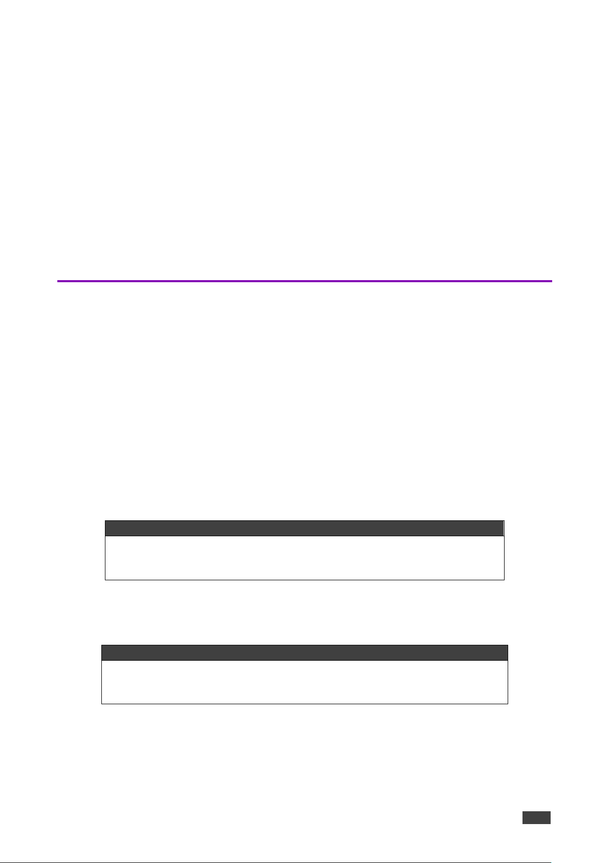
3. Navigate to the save location and double click the install package.
Setup page appears.
Figure 1: Setup Page
Kramer Electronics Ltd.
VSM on Cloud & VSM on Premises – Getting Started
5
4. Click Next on setup page.
The Ready to install window appears.
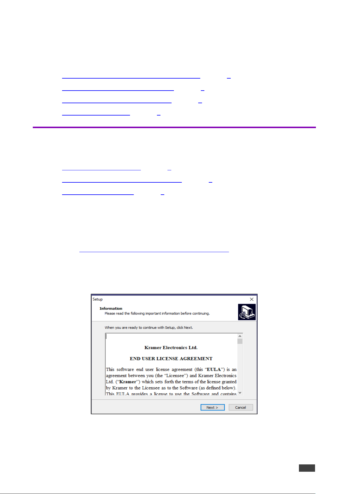
Figure 2: Setup Installation Page
5. Click Install to install page. The Server Installer window appears.
Figure 3: My SQL Password Page
6. Set My SQL Password or leave it blank to use default password.
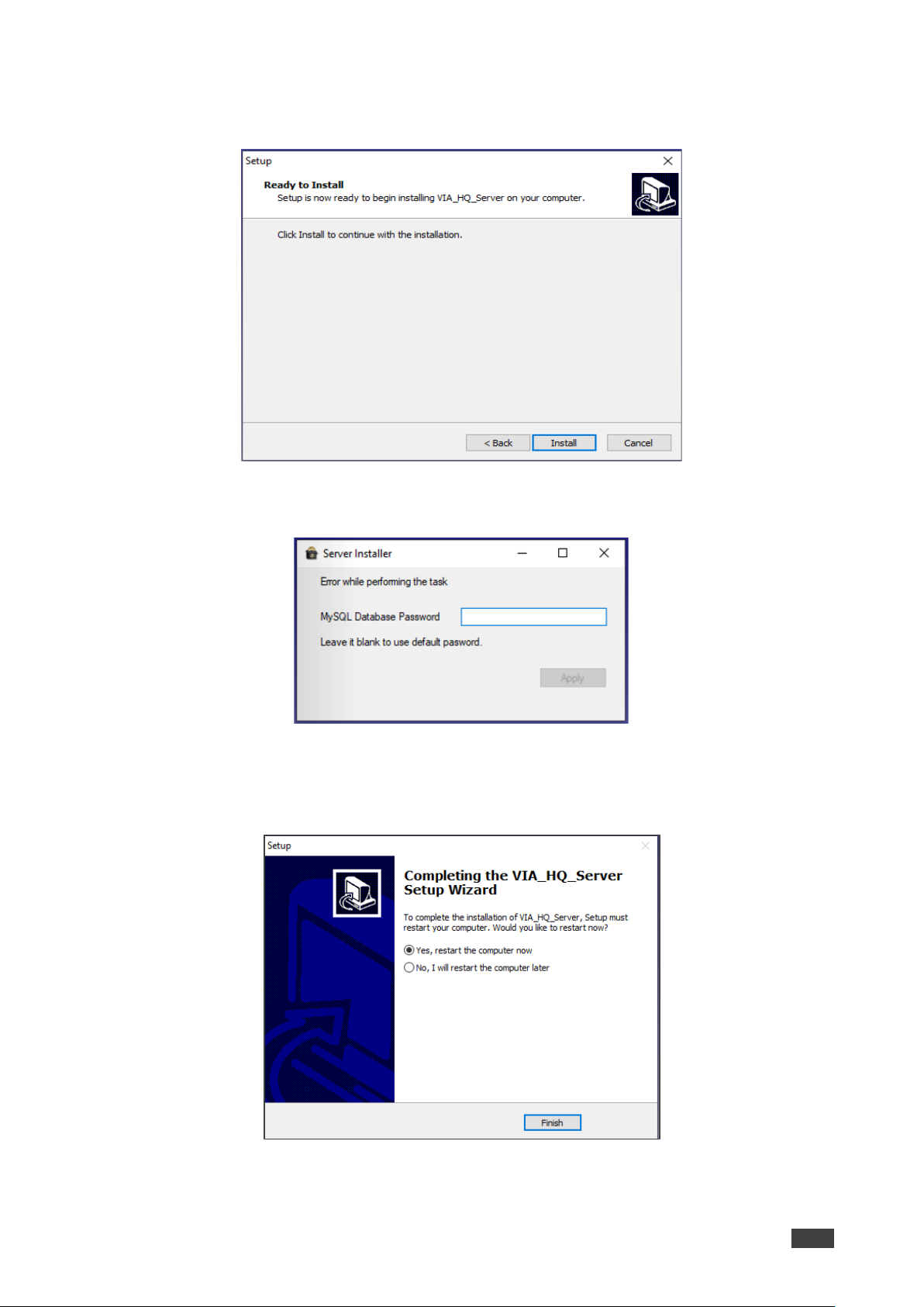
7. Click Apply. The Setup completion page appears.
Figure 4: Finish Setup

Kramer Electronics Ltd.
VSM on Cloud & VSM on Premises – Getting Started
6
8. Select Yes,restart the computer now and click Finish.
We recommended that you restart the device after finishing the setup.
9. Once the installation is complete and the VSM server is installed, a “VSM License”
application icon displays on your desktop.
Activating a License for VSM on Premises
To Activate Via Site Management License (only for VSM on Prem):
Make sure that the device is connected to the Internet.
1. Install VSM server (see Installing VSM on Premises on page 4), a “VSM License”
application icon displays
2. Double click on the VIA license icon on the desktop.
License management window appears.
Figure 5: License Management Window
3. Next to Enter Serial Number, enter the serial number that was provided at the time of
purchase.
4. Click Activate.
License is Activated.
In case any error occurs, contact the technical support team at support@kramerav.com.

Kramer Electronics Ltd.
VSM on Cloud & VSM on Premises – Getting Started
7
Logging to VSM on Prem
To log into VIA Site Management:
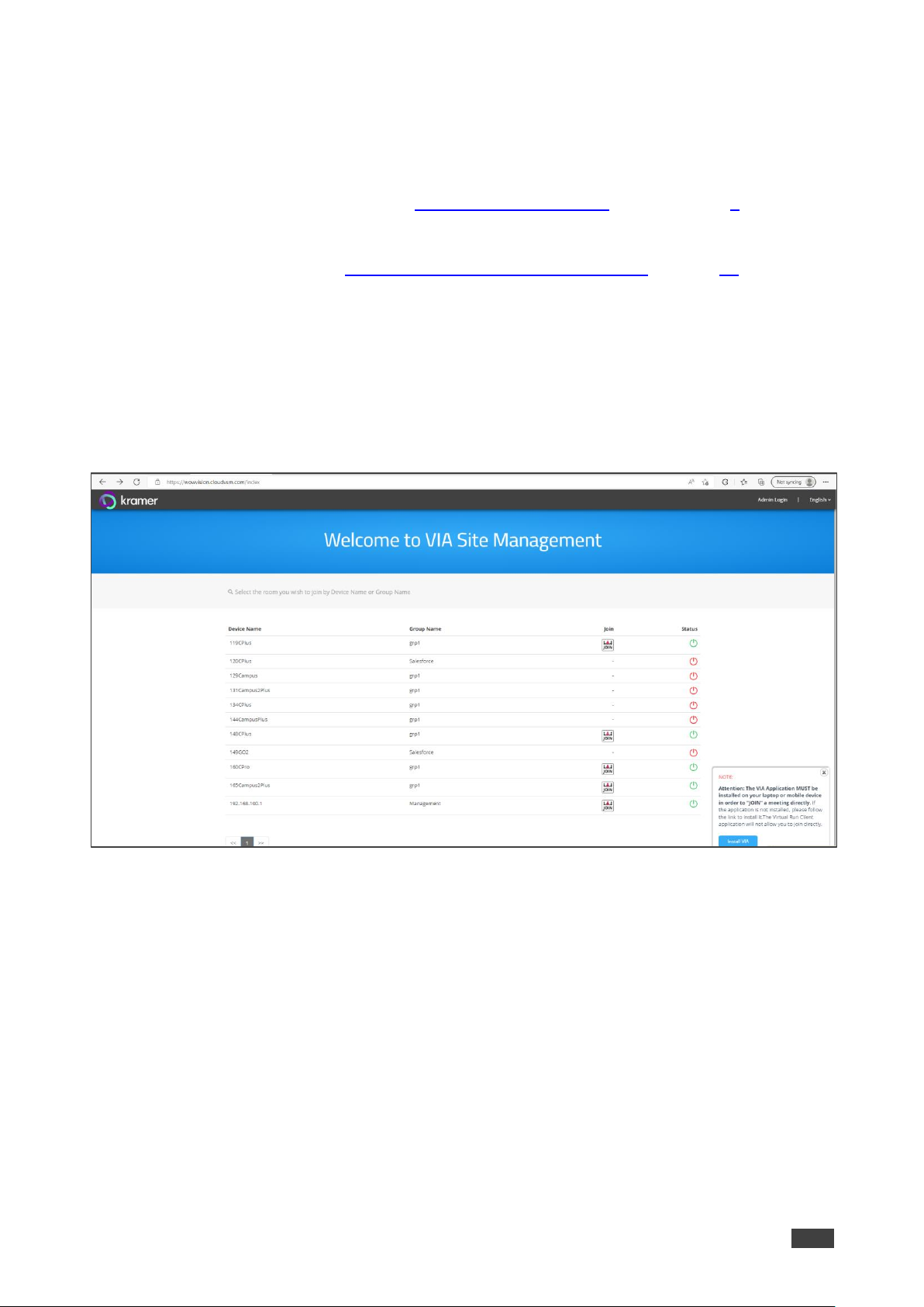
1. In a web browser, log in to the VIA Site Management software by typing the VSM IP
address (for example, the address http://192.168.100.125/).
The VSM Home page appears, listing all the VIA devices available on your network
(once configured):
Figure 6: VSM Home Page
To change the interface language, select the desired language from the English drop-down
box on the top right-side screen.
Setting VIA Site Management on Cloud
VIA Site Management on cloud is a cloud-based software for managing the gateways
without installing on server.
Setting up a New VSM on Cloud
To setup a new VSM on cloud:
1. Make sure you have the following details in hand:
▪ Product Id/ Duration in years/ Number of VIA device to manage in Qty (for example:
SW-00031/VSM-ON-CLOUD-SUB-1Y/QTY10).
▪ Customer Shipment and Sales Order number (for example: CS-2223302289, SO-
2213301744).
▪ The desired domain name that the customer would like to have for VSM (for
example: https://xxxxxxxx.cloudvsm.com).
Initial VSM server configuration and license activation is done at the time of purchase.
Kramer Electronics Ltd.
VSM on Cloud & VSM on Premises – Getting Started
8
Updating or Renewing an Existing VSM
To update or renew the existing VSM:
1. Contact the salesforce team.
2. Provide the required details (see Setting up a New VSM on Cloud on page 7).
3. License file will be generated and provided to the customer.
4. Upload license file (see Uploading VSM License (only for Cloud) on page 70).
Logging VSM on Cloud
To login VSM on Cloud
1. In the browser. click or type the URL link in the browser provided in the email at the time
of purchase (For example, <domainname>.cloudvsm.com/).
The VSM home page appears and shows a list of connected devices.
Figure 7: VSM Home Page

Kramer Electronics Ltd.
VSM on Cloud & VSM on Premises – Getting Started
9
Accessing the Administration Interface
To access the administration interface:
1. Click Admin login.
The Login page appears.
Figure 8: VSM Login Page
2. Enter the administrator’s User Name and Password:
▪ Type the administrator username In the User Name field.
▪ Type the administrator password in the Password field.
3. Type the Captcha and click Login.
You have logged into VSM.
Resetting the Password
To reset the password:
1. Click Forgot Password on Admin Login page.
The Forget Password window appears.
Figure 9: Forget Password Dialog Box
2. Type an email address In Email Id field and click Send Mail.
A link is sent to the email address to reset the password.

Kramer Electronics Ltd.
VSM on Cloud & VSM on Premises – User Management
10
User Management
User management helps a VIA Web administrator to create, edit and delete additional users
to manage the server.
Adding a User
To add a user:
1. Click USER MANAGEMENT → User List.
The User List Management window appears.
2. Click Add User.
3. The Add User window appears.
4. Type a user name in the Username field.
Text beside this field informs if the typed user name is available.
5. Type an Email Id associated with the new user.
6. Type a password in the Password field.
7. Type the same password in the Confirm Password field.
Users with unrestricted access such as ‘su’ can be created by the VSM’s user management.
8. To create users with unrestricted access:
a. Check User Management (Web Administrator).
This gives user unrestricted access to VSM.
b. Check the VSM Management box to create users which can access all menu options
listed under VSM Management.
9. Click Save.
Figure 10: User List Management Window

Kramer Electronics Ltd.
VSM on Cloud & VSM on Premises – User Management
11
Editing a User
To edit a user:
1. Click USER MANAGEMENT.
The User List management page appears.
Figure 11: User List
2. next to a username click to edit user name. the Edit User window appears.
Figure 12: Edit User Window
3. Edit the password and define the user type and authorization.
4. Click Update.
Kramer Electronics Ltd.
VSM on Cloud & VSM on Premises – User Management
12
Deleting a User
To delete a user:
1. Click USER MANAGEMENT.
The User List Management page appears.
2. Click in the Delete column of the user you want to delete.
A confirmation message to delete the group appears.
3. Click OK.
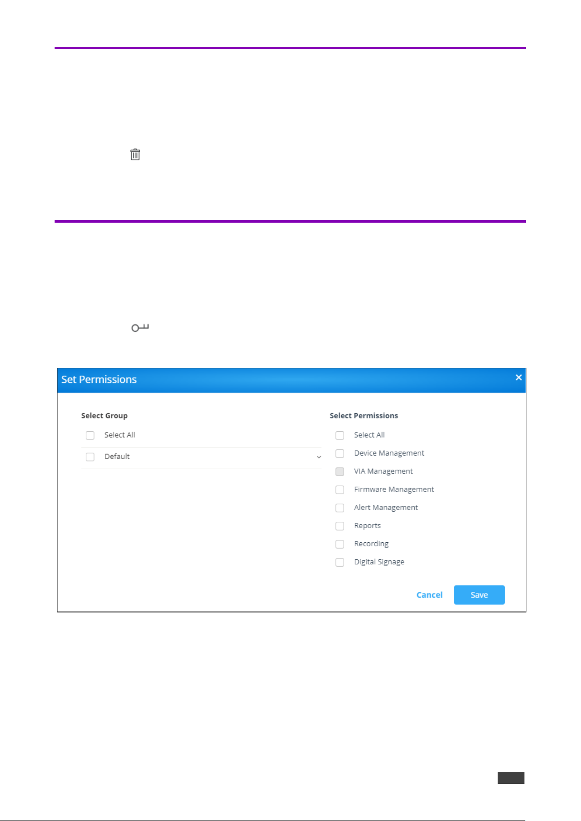
Editing Permissions
To edit user groups and permissions:
1. Click USER MANAGEMENT.
The User List page window appears.
2. Click in the Set Permissions column of the user you want to modify permissions.
The Set Permissions window appears.
Figure 13: User Permission Settings
3. Select the required permissions.
4. Click Save.
Kramer Electronics Ltd.
VSM on Cloud & VSM on Premises – User Management
13
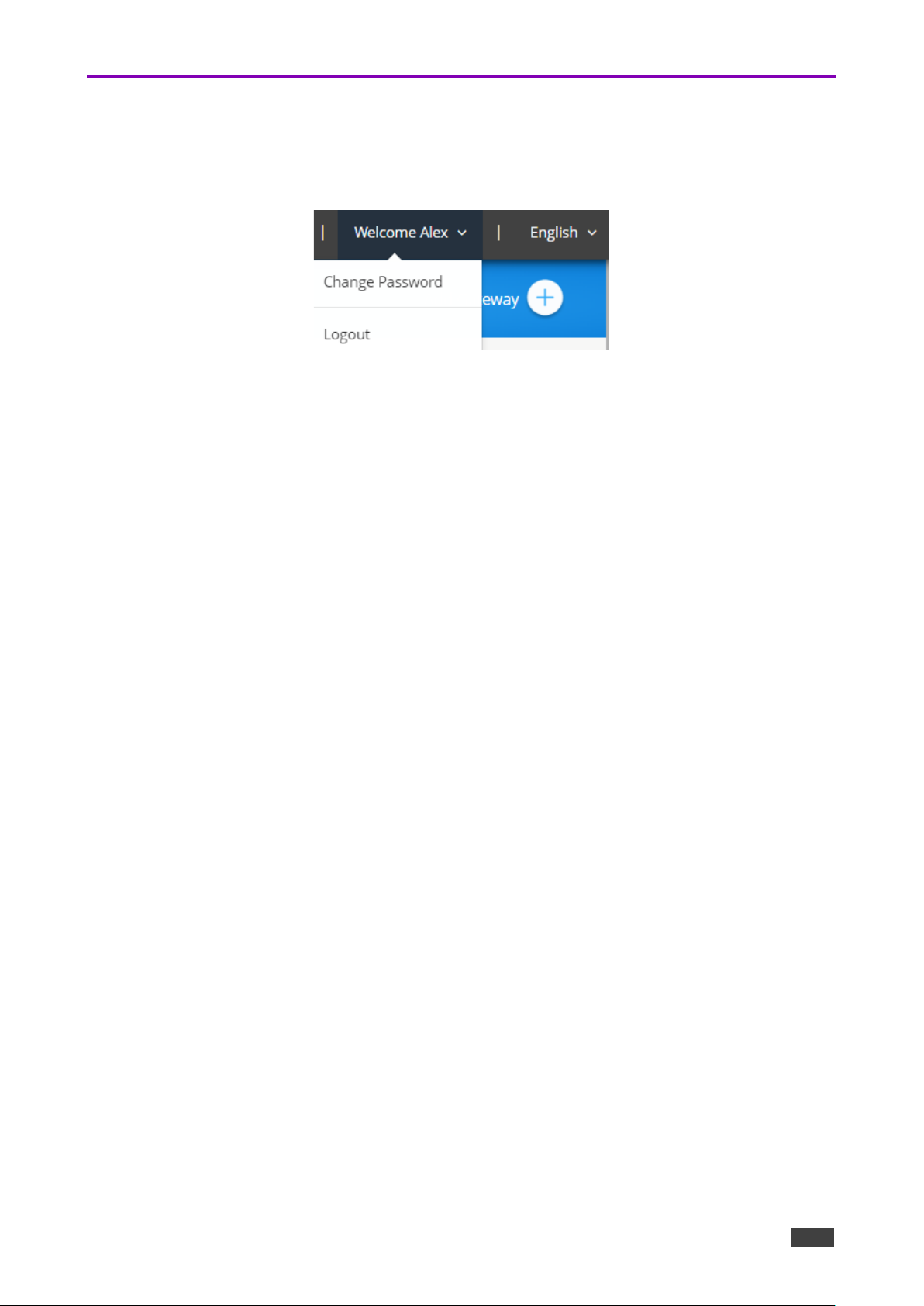
Changing the Password
To change password:
1. On the top right of the web pages, select Welcome [username] → Change Password.
Figure 14: Welcome User Dropdown
The Change Password window appears.
2. Type the old password in the Old Password field.
3. Type the new password in the New Password field.
4. Retype the new password in the Confirm Password field.
5. Click Update.
6. To clear typed values, click Reset.
Password has changed.
Kramer Electronics Ltd.
VSM on Cloud & VSM on Premises – Device Management
14
Device Management
VSM on Cloud & VSM on Premises enables managing multiple devices from one central
interface:
• Managing Groups on page 14.
• Managing Devices on page 16.
• Managing Configurations Template on page 30.
• Using VIA Screen Editor on page 47.
Managing Groups
VSM on Cloud & VSM on Premises enables managing groups for organizing your VIA
devices efficiently. You can add multiple devices a group name. For example, create a group
and name it by the floors in the office and then associate each device with a floor group
(see Adding a User on page 10).
To manage groups, perform the following actions:
• Creating a Group on page 14.
• Editing a Group on page 15.
• Deleting a Group on page 16.
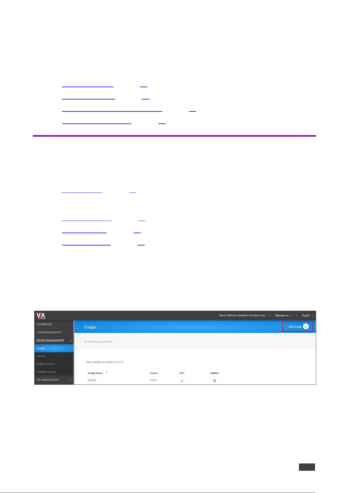
Creating a Group
To create a group:
1. Click DEVICE MANAGEMENT → Groups.
The Groups window appears.
Figure 15: Groups Window
Kramer Electronics Ltd.
VSM on Cloud & VSM on Premises – Device Management
15
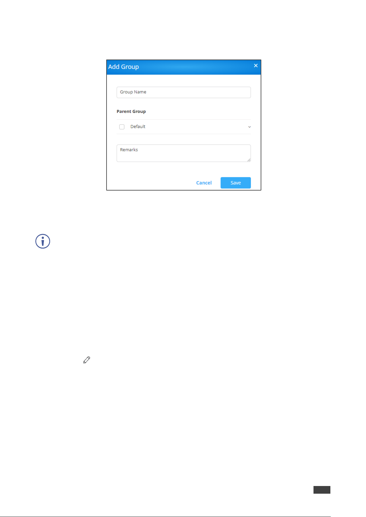
2. Click Add Group.
The Add Group window appears.
Figure 16: Add Group Window
3. Enter the Group Name (or parent group name).
4. Select a Parent Group.
You can create up to 5-level groups.
5. In Remarks enter the group details.
6. Click Save.
The group is created.
Editing a Group
To edit a group:
1. Click DEVICE MANAGEMENT → Groups.
The Groups window appears.
2. Click under the Edit column of the specific group.
The Edit Group window appears.
3. Edit the group information and click Update.
The group is edited.

Kramer Electronics Ltd.
VSM on Cloud & VSM on Premises – Device Management
16
Deleting a Group
To delete a group:
1. Click DEVICE MANAGEMENT → Groups.
The Groups window appears.
2. Click in the Delete column of the group you want to delete.
A confirmation message to delete the group appears.
3. Click OK.
The group is deleted.
Managing Devices
VSM on Cloud & VSM on Premises enables managing multiple VIA devices from one
interface. A new device can be added manually or be imported from a csv file.
Make sure that the Site Management Server and the devices are on the same network before
performing the following actions:
• Adding a Device via the VSM on Cloud & VSM on Premises Interface on page 16.
• Importing Devices on page 18.
• Editing/ Deleting a Device on page 19.
• Searching Devices on page 21.
Adding a Device via the VSM on Cloud & VSM on Premises Interface
VSM on Cloud & VSM on Premises enables adding a device to your VSM on Cloud & VSM
on Premises system using the VSM on Cloud & VSM on Premises interface.
To add a device using the VSM on Cloud & VSM on Premises interface:
1. Click DEVICE MANAGEMENT → Devices.
The Add/ Edit/ Delete Devices window appears.
Kramer Electronics Ltd.
VSM on Cloud & VSM on Premises – Device Management
17
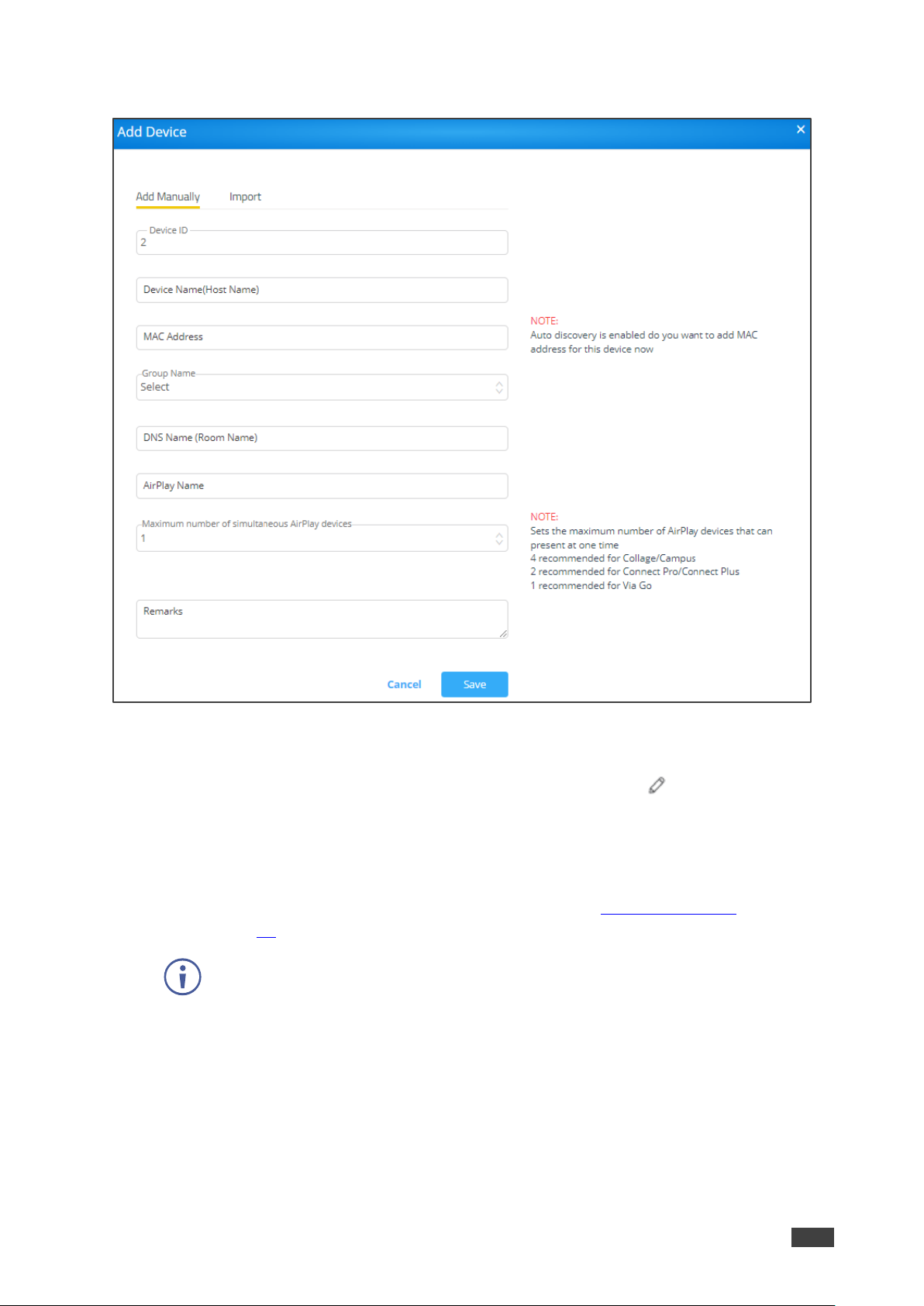
2. Click Add Device. The Add Manually tab in the Add Device window appears.
Figure 17: Add Device Window
3. Click Add Manually and enter the:
▪ Device ID: A unique number that identifies the device. Click to edit the device
name.
▪ Device Name (Host Name): A unique name that identifies the device.
▪ MAC Address: Enter the MAC address for auto-discovery.
▪ Group Name: Add the device to a created group (see Managing Groups
on page 14).
Make sure that the device does not have duplicate settings, while moving it from
one group to another group.
▪ DNS Name (Room Name): Relevant only if a DNS server is active in your network.

Kramer Electronics Ltd.
VSM on Cloud & VSM on Premises – Device Management
18
▪ AirPlay Name: An identifiable name for an iOS device to scan and connect
(optional).
▪ Maximum number of simultaneous AirPlay devices: The maximum number of
AirPlay devices that can present simultaneously.
We recommend that you set 4 for Collage/Campus devices, 2 for Connect
Pro/Connect Plus devices and 1 for VIA Go.
▪ Remarks: Additional information about the added device (optional).
4. Click Save.
The device is added.
Importing Devices
VSM on Cloud & VSM on Premises enables you to import a device to your VSM on Cloud &
VSM on Premises system using a csv file.
To import a device:
1. Click DEVICE MANAGEMENT → Devices.
The Add/ Edit/ Delete Devices window appears.
2. Click Add Device. The Add Manually tab in the Add Device window appears.
3. Click the Import tab. The Import tab appears.
4. Click Click here to download a template for entering device details to import.
The .csv file downloads.
5. Open the .csv file template in a spreadsheet application.
6. Fill in the details:
▪ Gateway ID: A unique number that identifies the device.
▪ Gateway Name: A unique name that identifies the device.
▪ Group Name: Connect the device to one of the groups that you created
(see Managing Groups on page 14). If a new group is imported, it is automatically
created.
▪ DNS Name: Relevant only if a DNS server is active in your network.
▪ Air Mirror Name: An identifiable name for an iOS device to scan and connect
(optional).
▪ Max No. Of Mirrored iOS Devices: Must conform to the rules for different device
models (see specifications for your VIA device model).
▪ Remarks: Additional information about the added device (optional).
▪ MAC address: Required if adding devices to VSM using VIA Discovery.
7. Save the file.
8. On the Import window, click Browse File to navigate to the saved file.
9. Click Import to add the device.

Kramer Electronics Ltd.
VSM on Cloud & VSM on Premises – Device Management
19
Editing/ Deleting a Device
To push configurations to a specific VIA unit:
1. Click DEVICE MANAGEMENT → Devices.
The Add/ Edit/ Delete Devices window appears.
2. Click and then click OK.
The status denotes VIA is updated to the latest version.
The green button indicates that the Device is powered ON and a red button indicates
that the Device is powered OFF.
3. Click the up/down arrow to sort a column in ascending or descending order.
To delete a device:
• Select the device and click Delete.
To reboot the Device/s:
• Select the device and click Reboot.
To reset a device session:
• Select the device and click Reset Session.
To export device information to a CSV file
• Click Export to CSV.
When upgrading VSM from 2.3 to 2.5 or 3.0, mirroring name is set with DNS Name or
Host name if DNS is not available.
Editing a Device
To edit device settings:
1. Click DEVICE MANAGEMENT → Devices.
The Add/ Edit/ Delete Devices window appears.
2. Click a device line. The device window appears.

Kramer Electronics Ltd.
VSM on Cloud & VSM on Premises – Device Management
20
Figure 18: Device Edit Window
3. If required, perform the following actions:
▪ Click Edit VIA Device to edit device settings (see Adding a Device via the VSM on
Cloud & VSM on Premises Interface on page 16).
▪ Click to go to the device webpage (when the device is powered).
▪ Reset/Reboot the device.
▪ View the device serial number and IP address.
▪ View the number of users.
▪ Click Screen Editor to update the screen editor to the VIA device and click OK.
▪ Click VIA Settings to update VIA settings to the VIA device and then click OK.
▪ Click Digital Signage to update digital signage to the VIA device and then click OK.
▪ View Storage Status.
4. Click Push Updates.
The device settings are edited.

Kramer Electronics Ltd.
VSM on Cloud & VSM on Premises – Device Management
21
Searching Devices
VSM on Cloud & VSM on Premises enables you to create filters to search for specific
devices in you network.
To search devices:
1. Click DEVICE MANAGEMENT → Devices.
The Add/ Edit/ Delete Devices window appears.
2. Click Add a filter and select from the following filters:
▪ Device Name
▪ Group Name
▪ Firmware Version
▪ Device IP
▪ Box Id
▪ Model Type
▪ Power Status
▪ Storage Status
3. Click OK.
The list of devices is filtered, enabling search.
Register VIA Units
After adding devices (see Adding a Device via the VSM on Cloud & VSM on Premises
Interface on page 16) you can register the list of devices.
To register VIA units:
1. Click DEVICE MANAGEMENT → Register Devices.
2. Click Kramer account credentials. The following window appears
Figure 19: Register VIA Units Window
3. In the Email and Password text boxes, enter your Kramer account credentials to
register your VIA devices.

Kramer Electronics Ltd.
VSM on Cloud & VSM on Premises – Device Management
22
4. Click Save.
VIA units are registered.
Adding and Managing a Calendar
VIA devices integrate with Office 365®, MS Exchange and Google calendar to display all
meetings and events scheduled for a room and manage them. VSM enables performing the
following actions:
• Adding Calendar Accounts on page 22.
• Managing the Calendar on page 25.
Adding Calendar Accounts
This section describes how to add a calendar to VSM:
• Adding Office 365 to Calendar Account on page 22.
• Adding MS Exchange to the Calendar Account on page 23.
• Adding Google Calendar to the Calendar on page 24.
Adding Office 365 to Calendar Account
When a resource mailbox (e.g. a room) is created, the Office365 administrator can define the
mailbox to be None, Impersonation or Delegate.
To add office 365 to the calendar account:
1. Click Device Management → Calendar Account. The Calendar Account page
appears.
Figure 20: Office 365 Basic Auth Calendar Account Window
Kramer Electronics Ltd.
VSM on Cloud & VSM on Premises – Device Management
23
2. Select Office 365 Basic Auth from Calendar Type drop-down.
3. Enter Username (type the email address authorized to create a meeting room).
4. Enter the Password.
5. Select the permission type.
6. Click Test & Save to check the validity of the calendar account. On success, the
Connection Successful message appears. The device starts displaying meeting room
information associated with this Office ID. The registered calendar account information
appears in the table.
7. To delete a calendar, click Delete.
Adding MS Exchange to the Calendar Account
VSM supports integration with Microsoft Exchange® Server.
When a resource mailbox (e.g. a room) is created, the Exchange® administrator can define
the mailbox to be None, Impersonation or Delegate.
When syncing a Microsoft Exchange resource mailbox with VIA calendar there is an option to
select if the mailbox type is Impersonation or Delegate.
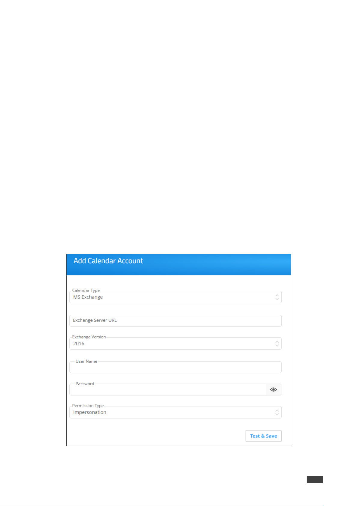
To add MS Exchange in calendar:
1. Click DEVICE MANAGEMENT → Calendar Account. The Calendar Account page
appears.
Figure 21: MS Exchange Calendar Account Window
2. Select MS Exchange from Calendar Type drop-down.
Kramer Electronics Ltd.
VSM on Cloud & VSM on Premises – Device Management
24
3. In Exchange Server URL, enter the Exchange server URL.
4. In Exchange Version, select an Exchange server version. The listed options are 2010,
2013, and 2016.
5. In Username, enter username.
6. Enter the Password (enter password for the resource mailbox to be synced).
7. In Permission Type, select Impersonation, Delegate or None. Contact your Exchange
Administrator to identify Delegate or Impersonation for your resource mailbox.
8. Click Test & Save to test if the details entered by you are correct. Once verified, it
synchronizes the calendar account with VIA Calendar. The registered calendar account
information appears in the table.
Adding Google Calendar to the Calendar
VIA devices integrate with Google Calendar to display all meetings and events scheduled for
a room.
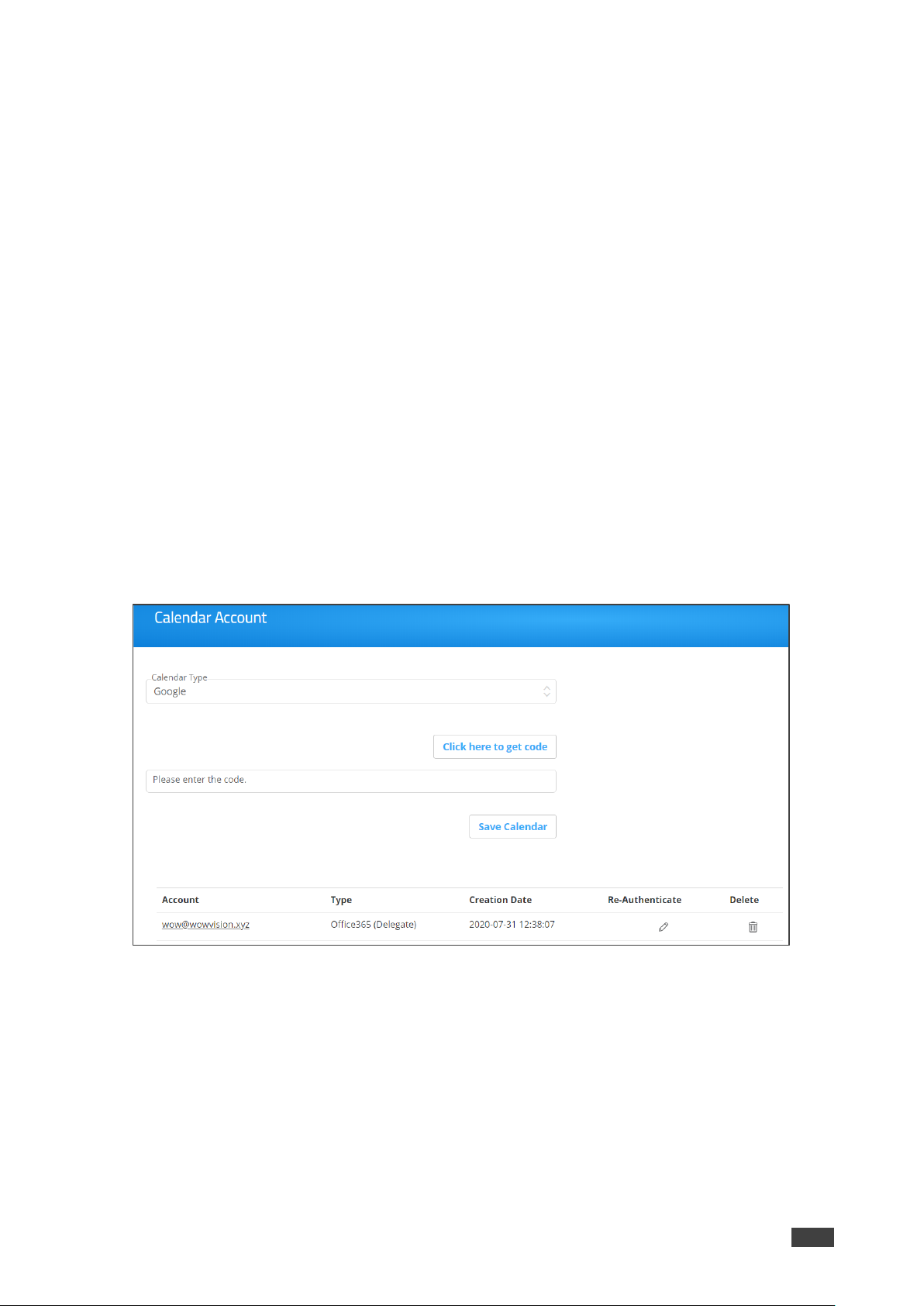
To add google calendar in calendar:
1. Click DEVICE MANAGEMENT → Calendar Account. The Calendar Account page
appears.
2. In Calendar Type, select Google.
Figure 22: Google Calendar Account Window
3. Click Click here to get code.
4. Sign-in with the Google account where a shared space calendar was created.
5. Allow access to event board.
6. Copy the code from the Sign in screen as shown below.

Kramer Electronics Ltd.
VSM on Cloud & VSM on Premises – Device Management
25
7. In Please enter the code, enter the code.
8. Click Save Calendar. The registered calendar account information appears in the table.
9. To delete the calendar, click Delete.
10. To re authenticate any account changes, click Re-Authenticate.
11. To delete the account, click Delete account. You cannot delete an associated account
with any device (link VIA).
Managing the Calendar
Once a calender is added, you can perform the following actions:
• Linking a VIA Device to a Calendar on page 25.
• Unlinking a VIA device from a Calendar on page 27.
• Viewing Sync Status on page 28.
Linking a VIA Device to a Calendar
Link a VIA device to an added calendar via (see Adding Calendar Accounts on page 22)
VSM.
To link a calendar:
1. Click DEVICE MANAGEMENT → Calendar Account.
The Calendar Account page appears.
Kramer Electronics Ltd.
VSM on Cloud & VSM on Premises – Device Management
26
Figure 23: Calendar Account Page
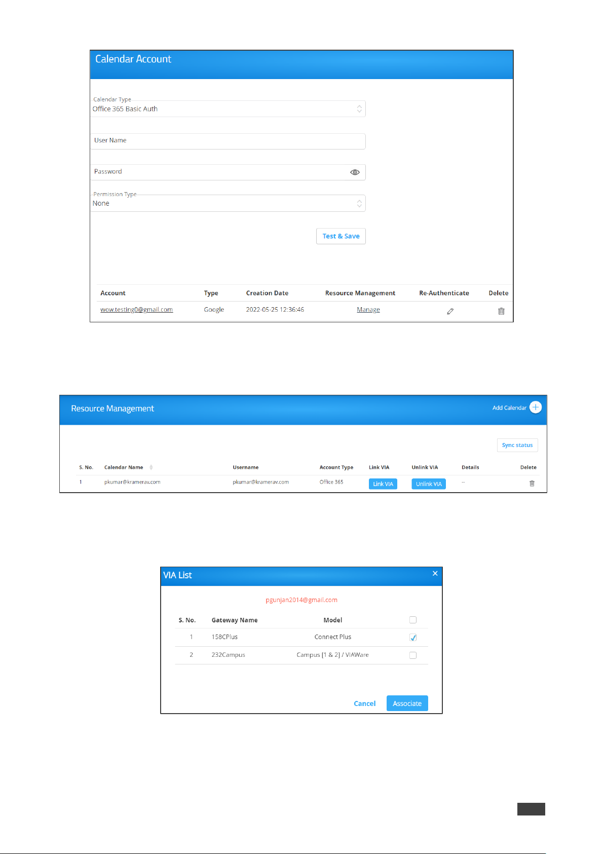
2. Select Manage (under Resource Management) on the relevant row.
The Resource Management window appears.
Figure 24: Resource Management Page
3. Click Link VIA in the relevant row.
The list of linked VIA devices appears.
Figure 25: Linked VIA Device List
4. Select the VIA device(s) to link with and click Associate.
An alert window appears.

Kramer Electronics Ltd.
VSM on Cloud & VSM on Premises – Device Management
27
5. Click OK. The Resource Management page reappears.
The linked device name displays under the Details column. If several devices are linked,
a Multiple link appears under the Details column).
Figure 26: Resource Management Page – Listing Linked Devices
6. Click Multiple (in this example). The linked VIA device list appears.
Figure 27: Linked VIA Device List
Unlinking a VIA device from a Calendar
Use VSM to unlink a VIA device with from the calendar.
To unlink a VIA device from a calendar:
1. Click DEVICE MANAGEMENT → Calendar Account.
The Calendar Account page appears.
2. Select Manage in the relevant row.
The Resource management window appears.
3. Click Unlink VIA in the relevant row.
The linked VIA device list appears.
Figure 28: Linked VIA Device List
4. Select the devices to unlink and click Delete. The alert window prompts.
Kramer Electronics Ltd.
VSM on Cloud & VSM on Premises – Device Management
28
5. Click OK.
The VIA device is unlinked from calendar.
Viewing Sync Status
To view the Sync status of VIA devices:
1. Click DEVICE MANAGEMENT → Calendar Account.
The Calendar Account page appears.
2. Select Manage on the relevant row.
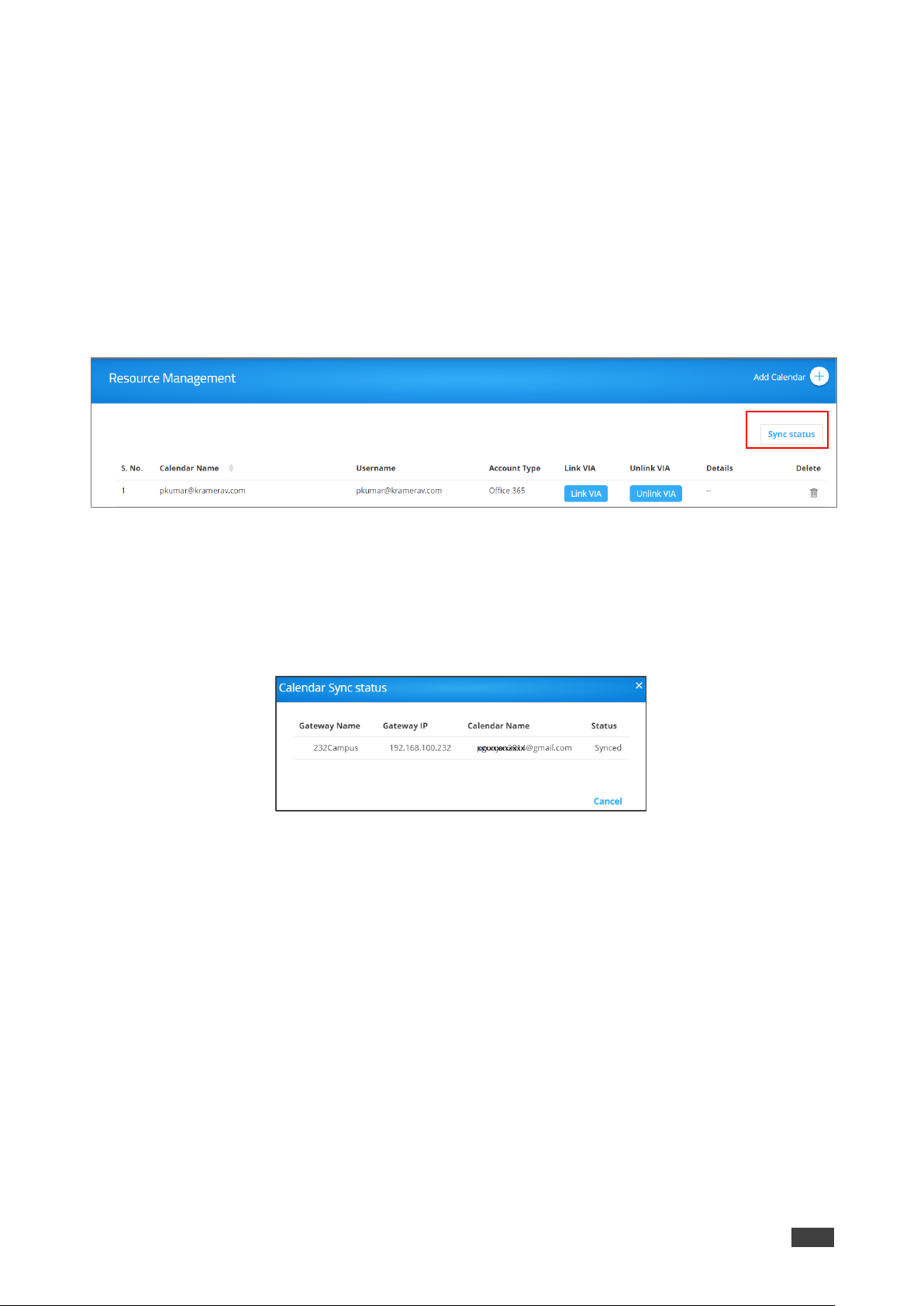
The Resource Management window appears.
Figure 29: Resource Management Page
3. Click Sync Status to display which devices have synced with the associated calendar
and which have not.
4. Click Cancel to close the window.
The calendar sync status window appears.
Figure 30: Calendar Sync Status Window
Kramer Electronics Ltd.
VSM on Cloud & VSM on Premises – Managing VIA
29
Managing VIA
Perform the following actions:
• Creating and Editing a Template on page 29.
• Managing Configurations Template on page 30.
• Using VIA Screen Editor on page 47.
Creating and Editing a Template
VSM Enables Creating a template which can then be configured to set all of aq VIA meeting
room needs.
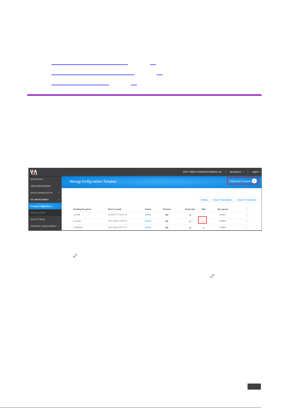
To create/edit a template:
1. Click VIA MANAGEMENT → Manage Configurations.
The Configurations Template Creation window appears.
Figure 31: Manage Configurations Template Window
2. perform any of the following options:
▪ Click (Edit) to edit an existing template.
▪ Click Create New Template.
▪ Click Duplicate to duplicate an existing template and then click (Edit).
The Configurations Template Creation window appears.
Kramer Electronics Ltd.
VSM on Cloud & VSM on Premises – Managing VIA
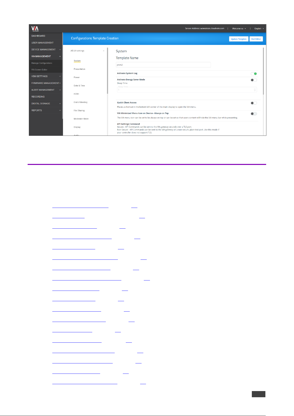
30
Figure 32: Configurations Template Creation Page
A template is created and can be edited.
Managing Configurations Template
Using VSM, you can configure the template settings, including VIA basic and advanced
settings:
• Configuring the System on page 31.
• Configuring a Presentation on page 31.
• Configuring Power on page 33.
• Configuring Date & Time on page 33.
• Configuring HDMI on page 33.
• Configuring End of Meeting on page 34.
• Configuring File Sharing on page 34.
• Configuring Moderator Mode on page 35.
• Configuring Display on page 38.
• Configuring Audio on page 38.
• Configuring Security on page 39.
• Configuring Certificate on page 41.
• Configuring NTP on page 41.
• Configuring the Host on page 42.
• Configuring RECORDING on page 43.
• Configuring Proxy Server on page 43.
• Configuring VIA GO on page 44.
• Configuring Campus PLUS on page 45.

Kramer Electronics Ltd.
VSM on Cloud & VSM on Premises – Managing VIA
31
• Configuring Connect PRO on page 45.
• Configuring Campus on page 46.
• Configuring Connect Plus/Connect2 on page 46.
Configuring the System
To configure the system:
1. Click VIA MANAGEMENT. The Configurations Template Creation window opens. The
System tab appears.
2. Enter the Template Name.
3. Slide the Activate System Log to on.
The Debug activity log is activated.
4. Slide Activate Energy Saver Mode to on. The energy saver mode is activated.
▪ Enter the sleep time duration. Energy saver mode automatically sends the VIA
Campus unit into sleep mode after the defining the minutes of inactivity.
5. Slide Quick Client Access to on.
The Quick Client Access mode is activated. This feature places a shortcut in the bottom
left corner of the main display to open the VIA menu.
6. Slide VIA Minimized Menu Icon on Gateway - Always on Top to on.
The VIA menu icon always appears on top of any content being displayed on the main
display.
7. Define API security settings, in the API Setting Command, by checking one of the
following:
a. Secure – API commands can be sent to the VIA device securely over a TLS port.
b. Non Secure – API commands can be sent to the VIA device on a non-secure, plain
text port. Select this option if your controller does not support TLS.
8. In Language, select the preferred language.
9. Under Broadcast, slide Bonjour and/or Bluetooth (BLE) to on.
10. Slide Third Party App Shortcut to on to allow access to third party users.
11. Hide VIAAdmin at the client side to hide the VIAAdmin user during a meeting from the
participants list.
12. Click Update Template.
System configuration is defined.
Configuring a Presentation
To configure a presentation:
1. Click VIA MANAGEMENT. The Configurations Template Creation window opens. The
System tab appears.
2. Click Presentation. The presentation tab appears.
3. Slide iOS Mirroring to set the VIA gateway to act as an Apple® AirPlay receiver.

Kramer Electronics Ltd.
VSM on Cloud & VSM on Premises – Managing VIA
32
4. Define Splash screen configuration:
▪ Slide Join through Browser to on to allow users to connect to VIA from web
browser. This activates support for Chrome browser.
▪ Slide Run VIA to on to allow users to install virtual client from splash screen.
▪ Slide Install VIA to on to allow users to download VIA Setup from splash screen.
5. Slide Miracast Settings to on to use KRAMER VIACast Dongle to enable this feature or
KRAMER recommend wifi dongles.
▪ Check 1 or 2 presenters.
6. Slide Reset Session to on to enable all users to reset a VIA session using the VIA tray
menu.
7. Check Auto/H264 or JPEG under Default Encoding for Presentation to enable PC &
Mac clients that are connected to the VIA gateway to default to the selected encoding
format.
▪ Slide Show Username to show the username of the presenter.
8. Reserve a screen for conferencing/media when in dual screen setup:
a. Slide Conferencing Mode or Media Mode to on to reseve a selected screen.
b. Check Primary Screen or Secondary Screen to assign that screen to the selected
operation mode.
The selected mode uses the selected screen and other applications can use the other
screen.
9. Slide Auto DND to on.
The DND (Do Not Disturb) feature prevents anyone but the active presenter from
presenting. Auto DND activates DND when a user starts presenting from their device.
10. Slide Do Not Disturb to on.
After a participant clicks the Present button, they are given the option to enable or
disable DND.
VSM enables you to activate the Do Not Disturb mirroring feature that enables any participant
that is using Kramer VIA app to mirror on the main display to prevent other participants from
mirroring. Slide the Do Not Disturb to on. Do Not Disturb is enabled following the next reboot.
11. Slide HDMI to VMD to on. When this feature is activated and a video source is
connected to the HDMI input, meeting participants are no longer able to present
wirelessly. Participant presentation features are blocked and they are only given the
option of the View Main Display feature.
12. Slide Local Annotation to on under VMD to enable the user to annotate locally on their
device while using the View Main Display feature. If this feature is not activated, users
can only view, but not annotate.
13. Slide Public Annotation to on under VMD to enable users to start public annotation
while using the View Main Display feature. When public annotation is started, the user’s
local annotation appears live on the main display, and the whiteboard tools are shown.

Kramer Electronics Ltd.
VSM on Cloud & VSM on Premises – Managing VIA
33
14. Slide Presentation Always in full Screen to on. When activated, only one user at a
time can present. When a new presentation is started, the current presentation stops.
15. Click Update Template.
Configuring Power
To configure power:
1. Click VIA MANAGEMENT. The Configurations Template Creation window opens. The
System tab appears.
2. Click Power tab.
The Power tab appears.
3. Slide Auto Power Off Timing to on.
▪ Select the time (hours and minutes) to set the VIA gateway auto shutdown time.
4. Slide Auto Reboot Timing to on.
▪ Select the time (hours and minutes) for the VIA to automatically reboot every day.
5. Click Update Template.
Configuring Date & Time
To configure the date and time:
1. Click VIA MANAGEMENT. The Configurations Template Creation window opens. The
System tab appears.
2. Click Date & Time.
The Date & Time tab appears.
3. Under Date and Time Format for Web interface, select a format from the Date Time
Format drop-down.
4. Under VIA Gateway Time zone Configuration, select the required time zone from the
Time Zone drop-down.
5. Click Update Template.
Configuring HDMI
Available for Campus Plus and Connect Plus devices.
To configure HDMI:
1. Click VIA MANAGEMENT. The Configurations Template Creation window opens. The
System tab appears.
2. Click HDMI.
The HDMI tab appears.
3. Slide Do not start HDMI input on startup to on to disable HDMI input on startup.
4. Slide Activate PIP Mode to on to activate PIP mode.

Kramer Electronics Ltd.
VSM on Cloud & VSM on Premises – Managing VIA
34
5. Slide HDMI Auto Switch to on to enable automatic switching to HDMI when a source is
connected to the HDMI input.
6. Slide Use HDMI Input as a camera source to on to use the HDMI input as a camera
source.
7. Click Update Template.
Configuring End of Meeting
To configure a meeting end:
1. Click VIA MANAGEMENT. The Configurations Template Creation window opens. The
System tab appears.
2. Click End of Meeting.
The End of Meeting tab appears.
3. In the End of Meeting Settings section, slide Clean the Cloud to on to select the desired
options when all participants have disconnected from VIA:
c. Close Whiteboard and Auto Save – Close the Whiteboard on the main display and
save the current page to the VIA cloud.
d. Close Whiteboard and Discard – Close the Whiteboard on the main display and
discard the current page.
e. Do not Close the Whiteboard – Leave the Whiteboard open on the main display.
4. Click Update Template.
Configuring File Sharing
To configure file sharing:
1. Click VIA MANAGEMENT. The Configurations Template Creation window opens. The
System tab appears.
2. Click File Sharing.
The File Sharing tab appears.
3. Select the types of files that can be shared. Select:
▪ All Files to select all the files.
▪ Selected Files to select specific file types that can be shared. The Manage File
Extensions window appears:

Kramer Electronics Ltd.
VSM on Cloud & VSM on Premises – Managing VIA
35
Figure 33: Manage File Extension Window
Check or uncheck file extensions as required and click Apply and/or add a new file
extension and click Add.
4. Click Update Template.
Configuring Moderator Mode
To configure the moderator mode:
1. Click VIA MANAGEMENT. The Configurations Template Creation window opens. The
System tab appears.
2. Click Moderator Mode on the navigation pane.
The Moderator Mode tab appears.
3. Slide Activate Moderator Mode to on.
4. Select a moderator mode:
▪ Selecting Basic Moderator Mode on page 35.
▪ Selecting Database Based Moderator Mode on page 36.
▪ Selecting Active Directory Mode on page 37.
5. Click Update Template.
Moderator Mode is configured.
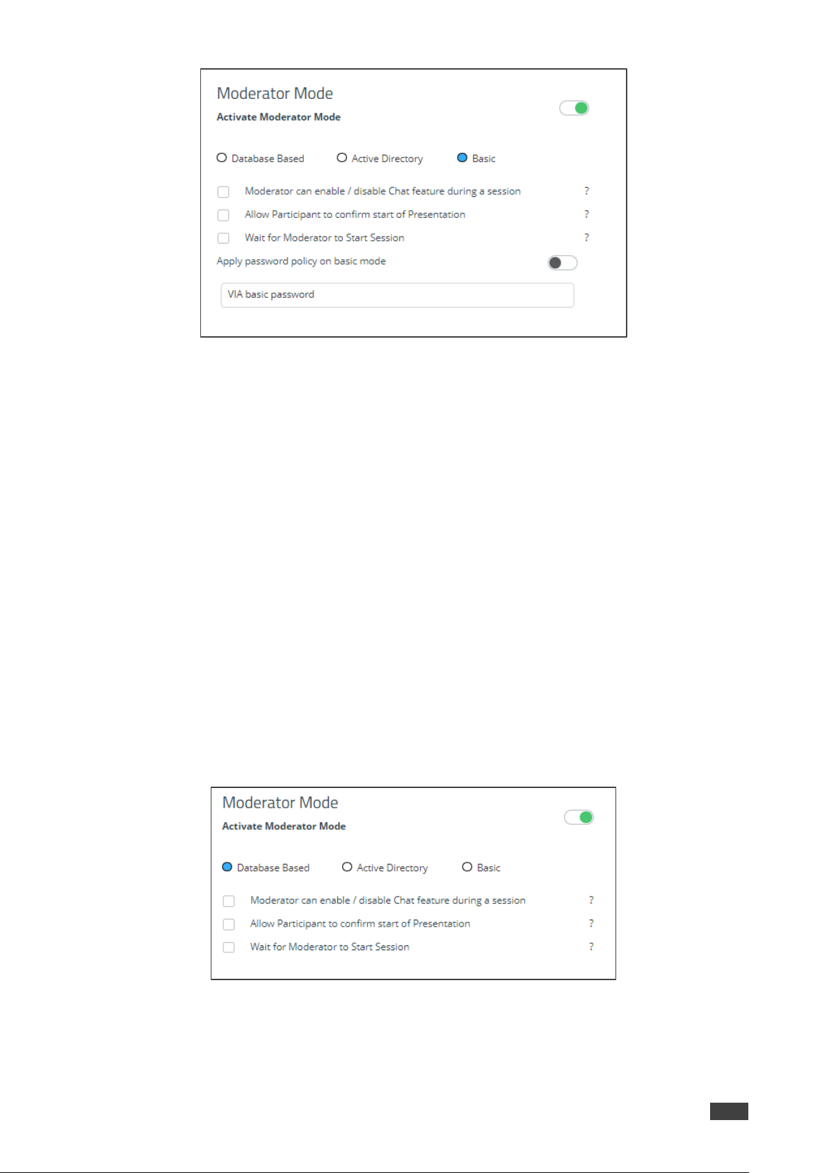
Selecting Basic Moderator Mode
The Basic mode allows anyone to join a meeting without a username and password and to
become a moderator using the VIA basic password defined by the Web Administrator.
To set the Basic mode:
1. In Moderator Mode, check Basic.
Kramer Electronics Ltd.
VSM on Cloud & VSM on Premises – Managing VIA
36
Figure 34:Moderator Mode – Basic
2. Check one or more of the following:
▪ Moderator can enable/disable Chat feature during a session – When enabled,
moderators can enable or disable participant chats during the session.
▪ Allow Participants to confirm start of Presentation – When enabled, the
participant is prompted to allow their presentation to be started when initiated from
the VIA gateway.
▪ Wait for Moderator to Start Session – A VIA session does not start until a
moderator joins the meeting. Participant dashboard features are grayed out and a
message appears on the main display.
3. Enter the VIA basic password.
Selecting Database Based Moderator Mode
In the Database Based mode, only users created by the Web Administrator can join a
meeting.
To set the Database Based mode:
1. In Moderator Mode, check Basic.
Figure 35:Moderator Mode – Basic
2. Check one or more of the following:
▪ Moderator can enable/disable Chat feature during a session – When enabled,
moderators can enable or disable participant chats during the session.
Kramer Electronics Ltd.
VSM on Cloud & VSM on Premises – Managing VIA
37
▪ Allow Participants to confirm start of Presentation – When enabled, the
participant is prompted to allow their presentation to be started when initiated from
the VIA gateway.
▪ Wait for Moderator to Start Session – A VIA session does not start until a
moderator joins the meeting. Participant dashboard features are grayed out and a
message appears on the main display.
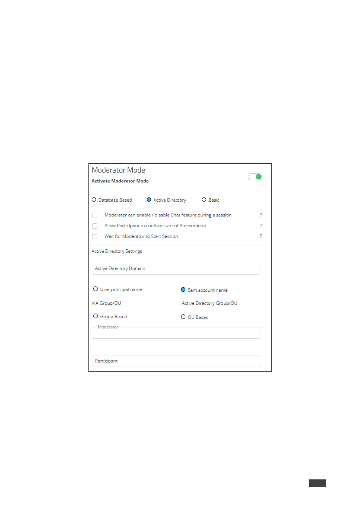
Selecting Active Directory Mode
Active Directory mode integrates with Active Directories (ADs) to avoid the hassle of creating
users from VIA Device Web UI.
To set the Active Directory mode:
1. In Moderator Mode, check Active DIrectory.
Figure 36:Moderator Mode – Active Directory
2. Check one or more of the following:
▪ Moderator can enable/disable Chat feature during a session – When enabled,
moderators can enable or disable participant chats during the session.
▪ Allow Participants to confirm start of Presentation – When enabled, the
participant is prompted to allow their presentation to be started when initiated from
the VIA gateway.
▪ Wait for Moderator to Start Session – A VIA session does not start until a
moderator joins the meeting. Participant dashboard features are grayed out and a
Kramer Electronics Ltd.
VSM on Cloud & VSM on Premises – Managing VIA
38
message appears on the main display.
3. Enter Active Directory Domain.
4. Select the User Principal Name or SAM Account Name or Group Based or
OU Based radio button as per the Active Directory configuration.
5. Based on the above selection, type the name of Moderator and Participant Group in
their respective boxes.
Active Directory Moderator Mode is configured.
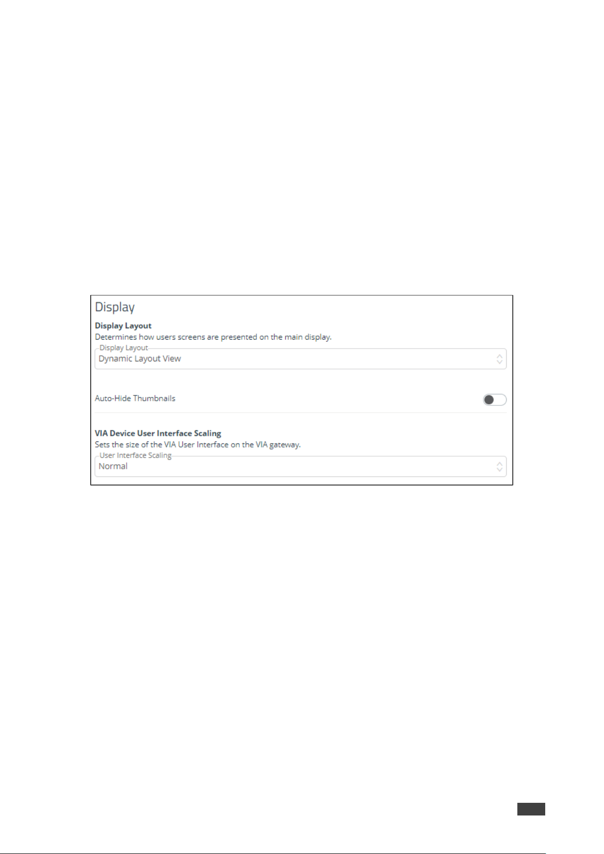
Configuring Display
1. Click VIA MANAGEMENT. The Configurations Template Creation window opens. The
System tab appears.
2. Click Display on the navigation pane.
The Display tab appears.
Figure 37:Display Tab
3. In Display Layout drop-down box, select layout view.
4. Slide Auto-hide Thumbnails to on.
5. In VIA Device User Interface Scaling, select appropriate size.
6. Click Save Template.
Configuring Audio
To configure the audio:
1. Click VIA MANAGEMENT. The Configurations Template Creation window opens. The
System tab appears.

Kramer Electronics Ltd.
VSM on Cloud & VSM on Premises – Managing VIA
39
2. Click Audio on the navigation pane.
The Audio tab appears.
Figure 38: Audio Tab
3. Select the required audio output to set the audio output as HDMI, display port or USB, in
the VIA Gateway Audio Output.
4. Select the desired defaukt volume level. After rebooting the unit, resetting a session, or
all users logging off, the volume returns to this defined level.
5. Click Update Template.
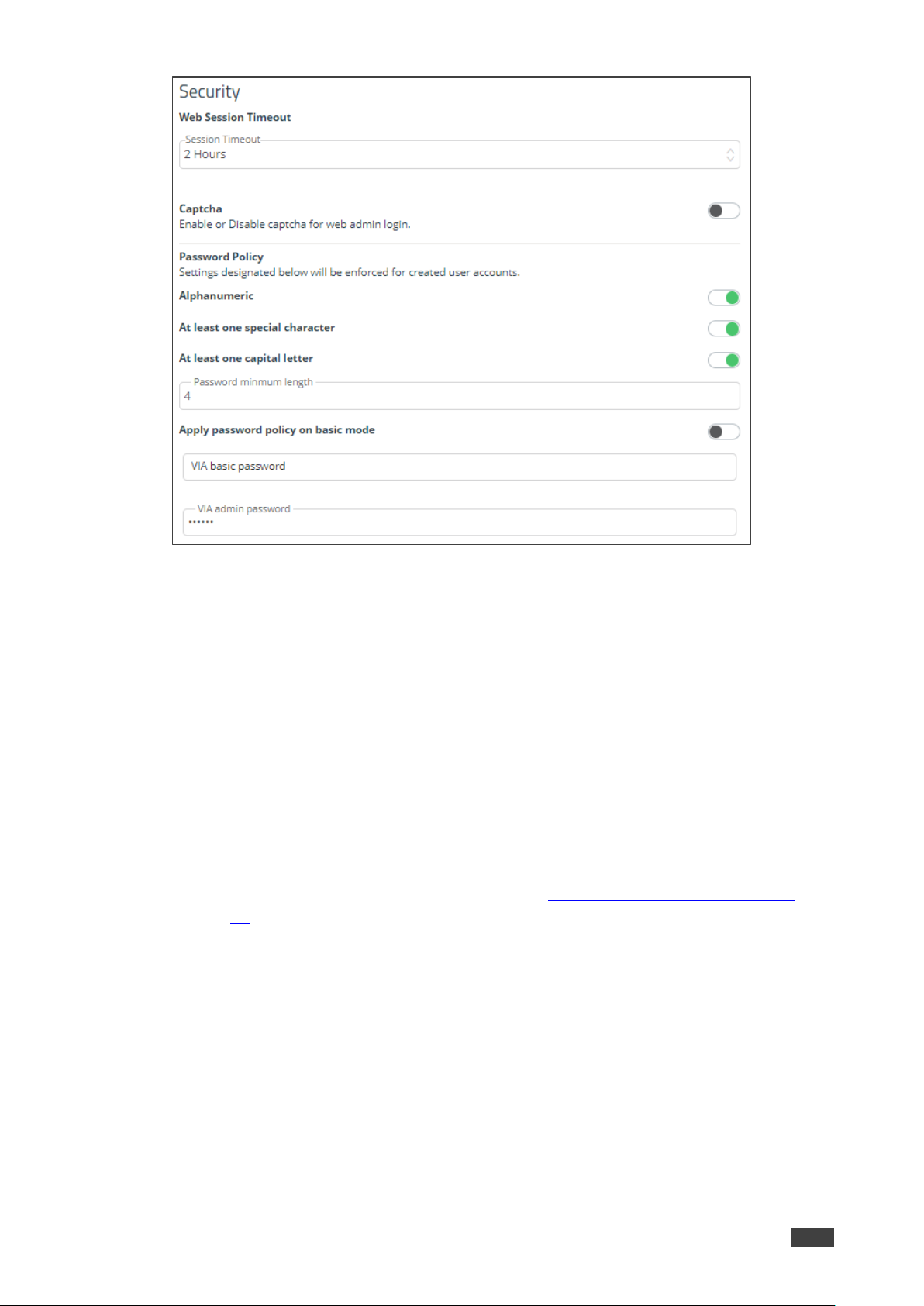
Configuring Security
1. Click VIA MANAGEMENT. The Configurations Template Creation window opens. The
System tab appears.
2. Click Security on the navigation pane.
The Security tab appears.
Kramer Electronics Ltd.
VSM on Cloud & VSM on Premises – Managing VIA
40
Figure 39: Security Tab
3. Under Web Session Timeout, select the desired Session Timeout period.
4. Slide Captcha to on to enable web admin login.
5. Under Password Policy, slide password settings to enhance VIA Device security for
created user accounts:
▪ Slide Alphanumeric to on.
▪ Slide At least one special character to on.
▪ Slide At least one capital letter to on.
6. Enter minimum password length.
7. Slide Apply password policy on basic mode – to allow anyone to join a meeting with
a password and to become moderator with a password defined by the Web
Administrator. Enter VIA basic password (see also Selecting Basic Moderator Mode
on page 35) and VIA admin password. The web admin defines the password for basic
mode and needs to adhere to the password policy.
8. Click Update Template.

Kramer Electronics Ltd.
VSM on Cloud & VSM on Premises – Managing VIA
41
Configuring Certificate
To perform this procedure, you need a valid SSL certification.
If you are configuring a world recognized domain on VSM, you need a valid, Apache
supported SSL certificate from Verisign, GoDaddy, ssl.com or other source.
If you locally manage a Certificate Authority (CA), you should generate the Apache supported
certificate. The (server.crt) and (server.key) files must be uploaded to:
C:\HQServer\htdocs\conf folder
After uploading these files, restart the Apache service.
To configure an SSL certificate:
1. Click VIA MANAGEMENT. The Configurations Template Creation window opens. The
System tab appears.
2. Click Certificate on the navigation pane.
The Certificate tab appears.
Figure 40: Certificate Tab
3. In copy and paste your certificate, copy and paste your certificate.
4. In copy and paste your key, copy and paste your key.
5. Click Update Template.
SSI certificate is configured.
Configuring NTP
To configure NTP:
1. Click VIA MANAGEMENT. The Configurations Template Creation window opens. The
System tab appears.

Kramer Electronics Ltd.
VSM on Cloud & VSM on Premises – Managing VIA
42
2. Click NTP on the navigation pane.
The NTP tab appears.
Figure 41: NTP Tab
3. In the Enter Server Name field, enter the address of the NTP server.
4. Click Add.
5. Click Save. The new NTP server is saved and appears in the NTP Server Name table.
6. To edit an NTP server name, click the icon in the Edit column.
7. To delete an NTP server name, click the icon in the Delete column.
8. Click Update Template.
NTP is configured.
Configuring the Host
To configure the Host:
1. Click VIA MANAGEMENT. The Configurations Template Creation window opens. The
System tab appears.
2. Click Host Configuration on the navigation pane.
The Host config tab appears.
Figure 42: Host Configuration Tab
3. Enter host configuration settings.
4. Click Save Template.
Host configuration is saved.

Kramer Electronics Ltd.
VSM on Cloud & VSM on Premises – Managing VIA
43
Configuring RECORDING
Recording is available only on Windows® devices.
To configure a recording:
1. Click VIA MANAGEMENT. The Configurations Template Creation window opens. The
System tab appears.
2. Click RECORDING. The Recording tab appears.
Figure 43: RECORDING Tab
3. Slide Activate Recording to on.
4. Select one of the following recording storage groups
▪ System Default – Save the recording to a selected location (by default to the VIA
hard drive).
▪ USB – Save the recording to an external USB drive.
▪ Cloud – Save the recording to the cloud.
▪ VSM – Save the recording to the VSM server.
5. Click Update Template.
Recording configuration is saved.
Configuring Proxy Server
To configure a proxy server:
1. Click VIA MANAGEMENT. The Configurations Template Creation window opens. The
System tab appears.
2. Click Proxy Server on the navigation pane.
The Proxy Server tab appears.

Kramer Electronics Ltd.
VSM on Cloud & VSM on Premises – Managing VIA
44
Figure 44: Proxy Server Tab
3. Enter the Server Name.
4. Enter the Port Number.
5. Enter the User Name.
6. Enter the Password.
7. Enter Proxy URL.
8. Click Test Proxy Server. On success, a connection successful message appears.
9. Click Update Template.
Proxy server is configured.
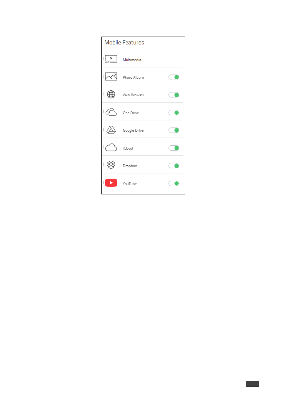
Configuring VIA GO
To configure VIA Go:
1. Click VIA MANAGEMENT. The Configurations Template Creation window opens. The
System tab appears.
2. Click VIA GO [1 & 2] on the navigation pane.
VIA GO tab appears.
3. Click Client Features and slide YouTube to on.
Figure 45: VIA GO 1& 2 Tab – Client Features
Kramer Electronics Ltd.
VSM on Cloud & VSM on Premises – Managing VIA
45
4. Click Mobile Features and slide the desired mobile features to on.
Figure 46: VIA GO 1& 2 Tab – Mobile Features
5. Click Update Template.
Client and mobile features are configured on VIA GO device.
Configuring Campus PLUS
To configure Campus PLUS:
1. Click VIA MANAGEMENT. The Configurations Template Creation window opens. The
System tab appears.
2. Click Campus PLUS [1 & 2] on the navigation pane.
The Campus PLUS tab appears.
3. Slide to on the respective Device, Client and Mobile features.
4. Click Update Template.
Client and mobile features are configured on VIA Campus PLUS device.
Configuring Connect PRO
To configure Connect PRO:
1. Click VIA MANAGEMENT. The Configurations Template Creation window opens. The
System tab appears.
2. Click Connect PRO on the navigation pane.
The Connect PRO tab appears.

Kramer Electronics Ltd.
VSM on Cloud & VSM on Premises – Managing VIA
46
3. Slide to on the respective Device, Client and Mobile features.
4. Click Update Template.
Client and mobile features are configured on VIA Connect PRO device.
Configuring Campus
To configure Campus:
1. Click Device Management → Manage Configurations.
The Manage Configurations Template window appears.
2. Click Campus [1 & 2] on the navigation pane.
The Campus tab appears.
3. Slide to on the respective Device, Client and Mobile features..
4. Click Update Template.
Client and mobile features are configured on VIA Campus device.
Configuring Connect Plus/Connect2
To configure VIA Connect Plus/Connect2:
1. Click VIA MANAGEMENT. The Configurations Template Creation window opens. The
System tab appears.
2. Click Connect Plus, Connect 2 on the navigation pane.
The Connect Plus tab appears.
3. Slide to on the respective Device, Client and Mobile features..
4. Click Save Template. Click Save Template.
Client and mobile features are configured on VIA Connect PRO device.

Kramer Electronics Ltd.
VSM on Cloud & VSM on Premises – Managing VIA
47
Using VIA Screen Editor
VIA Screen Editor is a web interface, where users can modify a device’s display layout like
placement of date and time, room name, room code and changing the wallpaper. It also helps
change the properties such as activating the room code, room name overlay and other
options.
Deleting a Template
To delete a template:
1. Click VIA MANAGEMENT → VIA Screen Editor.
The Screen Editor window appears.
2. Select the template and click Delete to delete an existing template.
This option is not available for the Default/Active template.

Kramer Electronics Ltd.
VSM on Cloud & VSM on Premises – Managing VIA
48
Editing a Template
To edit a template:
1. Click VIA Management → VIA Screen Editor.
The list of templates appears.
2. Click in the Edit column of the template you want to edit.
3. The Screen Editor window appears.
Figure 47: Screen Editor Window
When editing, Save has a small down arrow. Clicking it reveals Save As, to save the
template with a different name.
4. Edit the template as required and click
▪ Save to save the template. OR
▪ Save As (by clicking the save drop down arrow) to save the template with a different
name.
Edited Template is saved.
Importing & Exporting Templates
You can export a template and import it to a different device (to use with other devices).
To export a template:
1. Click Device Management → VIA Screen Editor.
The VIA Screen Editor window appears.
2. Select a template (or multiple templates) which you want to export.
3. Click Export Templates.
A confirmation message to delete the group appears.
4. Click OK.
Exported template is downloaded.

Kramer Electronics Ltd.
VSM on Cloud & VSM on Premises – Managing VIA
49
Since the templates are uploaded through a web interface, the same computer can be used
to access both devices.
To import a template to another device:
1. Click Device Management → VIA Screen Editor.
The VIA Screen Editor window appears.
2. Click Import Templates on the other device.
3. Navigate to the location where the exported template was saved.
4. Select the file and click Open.
Imported template displays in the template list of the other device.
Previewing Templates
To preview templates:
1. Click Device Management → Add Screen Layout.
The VIA Screen Layout window appears.
2. Click VIA Screen Editor → Add Screen Layout.
3. Add Wallpaper widget and drag a wallpaper from right or upload from computer.
4. Add any required widgets.
5. Click Preview.

Kramer Electronics Ltd.
VSM on Cloud & VSM on Premises – Managing VIA
50
Adding a Screen Layout
The window below appears and shows how the arrangement would appear on main display.
To add a screen layout:
1. Click VIA Management → VIA Screen Editor.
VIA screen editor page appears.
Figure 48: VIA Screen Editor Page
2. Click Add Screen Layout to create new template.
VIA screen editor window appears.
Figure 49: VIA Screen Editor Window
3. Perform below steps to configure template:
▪ Uploading Wallpaper on page 52.
▪ Adding Text on page 53.
▪ Adding Room Name on page 55.
▪ Adding Room Name 2 on page 57.
▪ Adding Room Code on page 58.
▪ Adding Code Popup on page 60.
▪ Adding Date on page 61.

Kramer Electronics Ltd.
VSM on Cloud & VSM on Premises – Managing VIA
51
▪ Adding Time on page 62.
▪ Adding Date & Time on page 63.
▪ Adding Adding QR Code on page 64.
▪ Adding a Calendar on page 65.
▪ Adding Timer on page 67.
4. Click Save to save the changes made by you in the list of templates. This appears as a
template when VIA screen editor is launched.
All changes will be lost if you do not click save before exiting.
5. Click Preview to view the changes that you have made. For preview to work, a
wallpaper must be uploaded.
6. Select Gridlines to display a grid that can be used to correctly align elements. This grid
only appears on the VIA screen editor and not on the main display.
Figure 50: VIA Screen Editor with Gridlines
7. Click Exit Editor to return to VIA Screen editor template list.
Kramer Electronics Ltd.
VSM on Cloud & VSM on Premises – Managing VIA
52
Uploading Wallpaper
Upload the wallpaper onto the device screen.
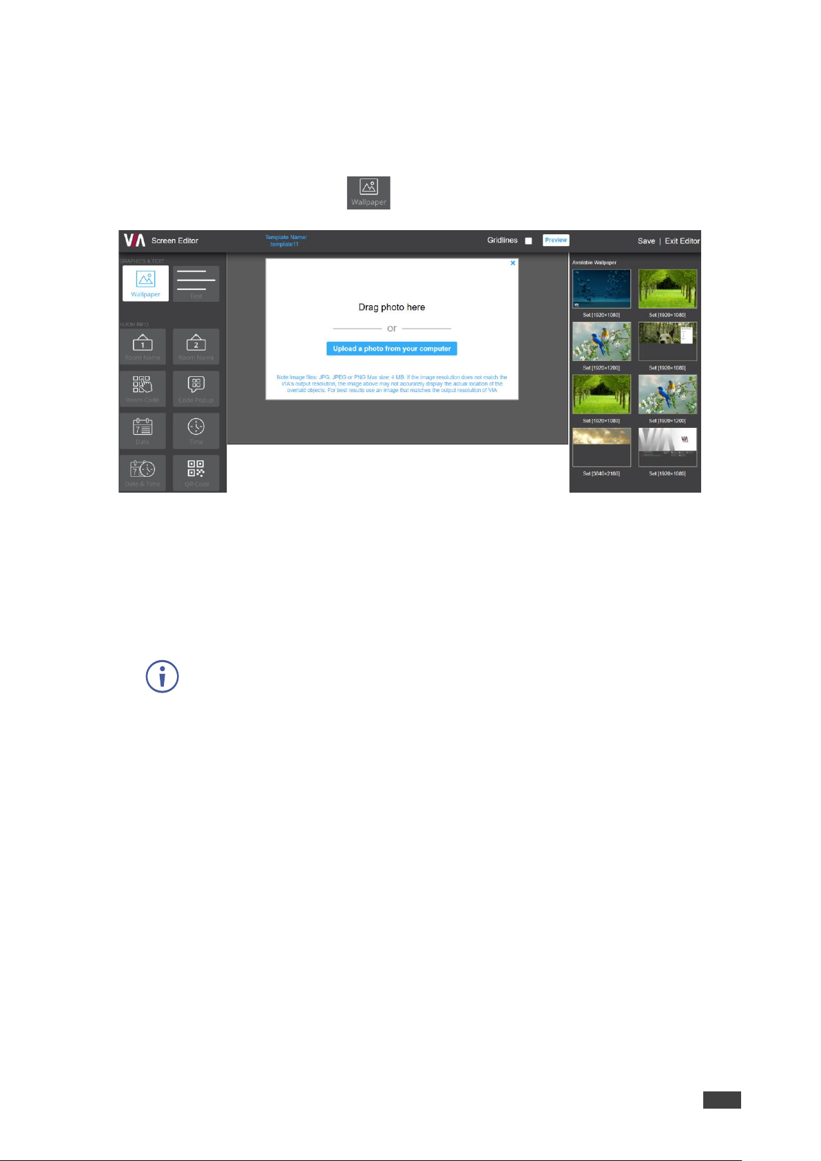
To upload a wallpaper to the device:
1. In the Screen Editor, click the icon.
Figure 51: Upload Wallpaper - Screen Editor
2. Upload the wallpaper in any of the following ways:
▪ Click and drag the image to the center area if the desired wallpaper image is
available on the right-side pane.
▪ Click Upload a photo from your computer if you need to upload a new wallpaper
image.
Select a wallpaper file size that does not exceed 4 MB.
Supported file extensions are PNG, JPG, and JPEG.
After uploading the wallpaper, its information is displayed.

Kramer Electronics Ltd.
VSM on Cloud & VSM on Premises – Managing VIA
53
Adding Text
To add text to the wallpaper:
1. Click and drag onto the center wallpaper area to add a text box.
Figure 52: Text - Screen Editor
2. Select PROPERTIES tab on the right-side pane to enter the text and set its properties:
a. Enter the message to appear on the device in the Text[1] field.
Text box numbers change in sequence for each subsequent text box that you add.
Figure 53: PROPERTIES Pane
b. Add text as shown in the note on the right-hand side to display the following
information:
#ipaddress1#: IP address of primary network.
#ipaddress2#: IP address of secondary network.
#apname#: Wireless SSID when VIA is configured in Access Point Mode.

Kramer Electronics Ltd.
VSM on Cloud & VSM on Premises – Managing VIA
54
#appass#: Wireless network password when VIA is configured in Access Point
Mode.
#airplayname#: AirPlay name.
c. Under Show Text on second Display also (Dual Display Only), move slider to ON to
automatically display text on second connected display.
d. Select the font size for the text as it appears on the device.
e. Select the text alignment.
f. Auto resize toggle: move slider to ON to ensure that there are no cropped areas in
the displayed information. The border of the box is reset as per the size of the text.
This change is seen on the device and not while the template is still being created.
3. Select COLORS tab on the right-side pane to set text colors:
Figure 54: COLORS Pane
a. Click Background Color to change the text box background color.
By default, the background is set to None (transparent background).
Figure 55: Background Color
b. Set the Opacity of the background (after setting a background color).
Note that if opacity is set to 10%, the textbox background color becomes
transparent on the main display.
Kramer Electronics Ltd.
VSM on Cloud & VSM on Premises – Managing VIA
55
c. Select the text font color (white, by default).
d. Toggle border (enable or disable) to show border on the main display.
e. If Border is enabled, select border color.
Adding Room Name
Add the room name.
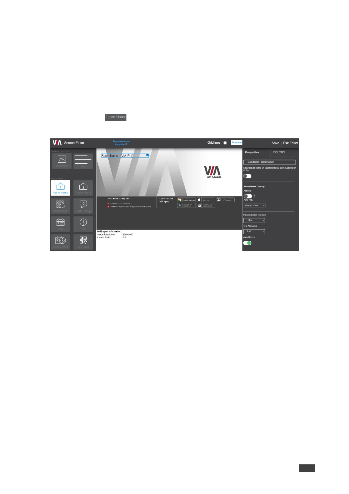
To add a room name:
1. Click and drag onto the center area to add a room name to the main display.
The right pane displays all the properties associated with room name.
Figure 56: Room Name - Screen Editor
Kramer Electronics Ltd.
VSM on Cloud & VSM on Premises – Managing VIA
56
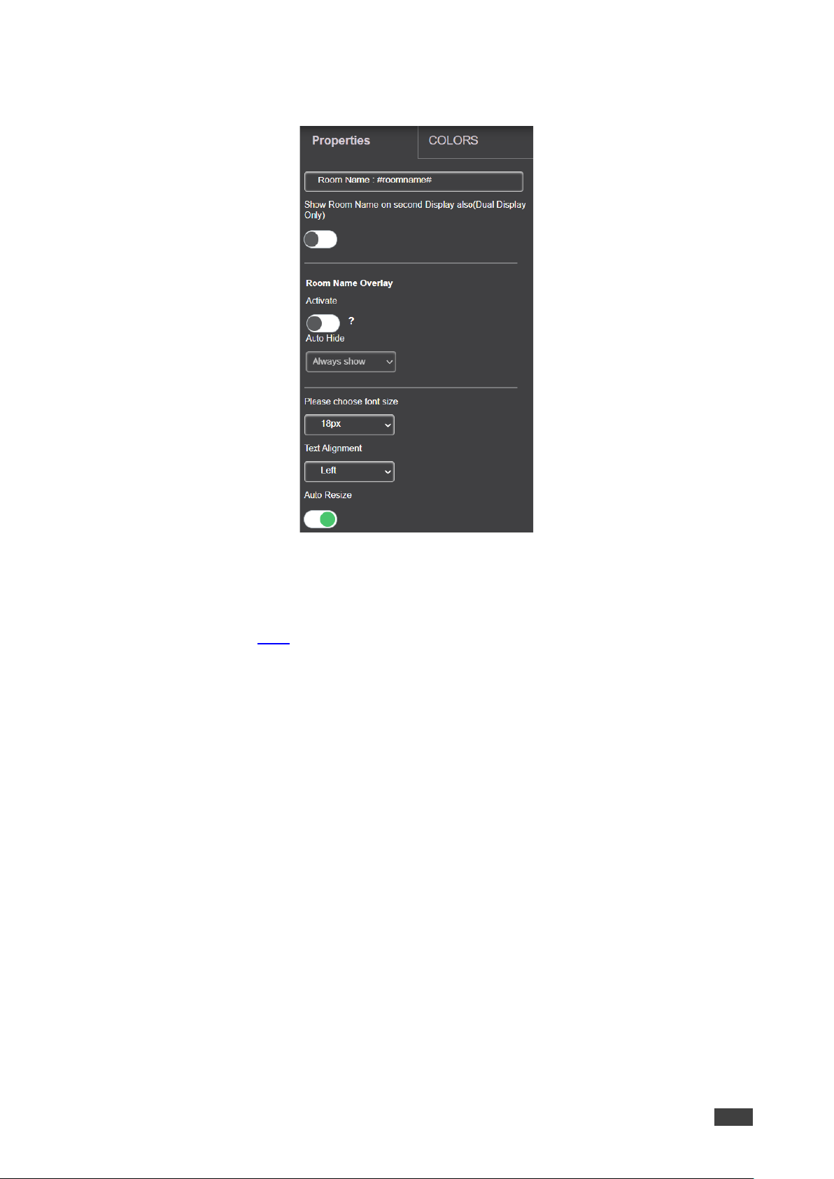
2. Select PROPERTIES tab on the right-side pane to enter the room name and set its
properties:
a. Enter Room Name.
This field can be edited to read anything. #roomname# for example, IP address of
the device is displayed here. So, Room Name: #roomname# is displayed on the
device as Room Name: <IP address of device>. To replace #roomname# with some
other text, a DNS must be configured. Type #AirplayName# to replace IP address of
the device with its AirPlay® Name.
b. Toggle Show Room Name on second Display also (Dual Display Only) to ON to
display the room name on the second display that is connected to the device
(Campus 2, Campus, Campus 2 Plus and Campus Plus).
c. Activate Room Name Overlay.
Room name overlay is a bar which appears on top and displays the room name for
participants to login. This is especially helpful during presentations when room name
on the wallpaper is hidden.
Room Name Overlay can be activated by clicking the Activate toggle.
To keep the overlay visible at all times, select Always Show; otherwise select a
time (in seconds) after which the overlay should disappear.
To keep the overlay visible at DSS only, select Show only with DSS.
d. Set the room name font size.
e. Select the text alignment.
f. Auto resize toggle: move slider to ON to ensure that there are no cropped areas in
the displayed information. The border of the box is reset as per the size of the text.
This change is seen on the device and not while the template is still being created.

Kramer Electronics Ltd.
VSM on Cloud & VSM on Premises – Managing VIA
57
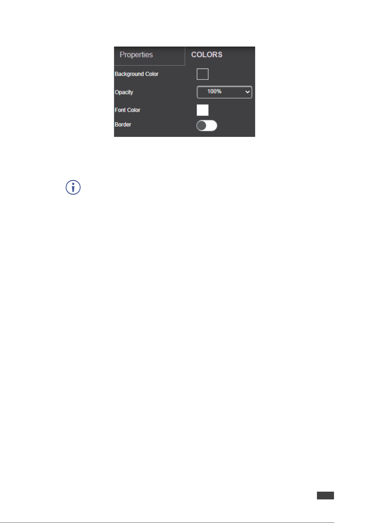
3. Select COLORS tab on the right-side pane to set text colors:
a. Click Background Color to change the text box background color.
By default, the background is set to None (transparent background).
Figure 57: Background Color
b. Set the Opacity of the background (after setting a background color).
Note that if opacity is set to 10%, the textbox background color becomes
transparent on the main display.
c. Select the text font color (white, by default).
d. Toggle border (enable or disable) to show border on the main display.
Adding Room Name 2
This icon is always seen on VIA screen Editor. However, Room Name 2 appears on the
device main display only when configured with dual network and subsequently has two
working IP addresses. The properties and color options are the same as Room
Name(see Adding Room Name on page 55).
This is visible only when a dual network is configured on VIA.

Kramer Electronics Ltd.
VSM on Cloud & VSM on Premises – Managing VIA
58
Adding Room Code
To add a room code:
1. Click and drag onto the center area to add the Room Code box to show on main
display.
The right pane displays all the properties and colors associated with Room Code.
2. Select PROPERTIES tab on the right-side pane to enter the text and set its properties:
a. Code: This has two parts. If #roomcode# is changed to a different code, that is the
code for new participants to log in. Room Code refresh time has no effect on the
custom room code. The text ‘Code’ is just a label. It can be renamed to anything or
can be removed altogether.
b. Toggle Show Room Code on second Display also (Dual Display Only) move slider
to ON to display the room code on the second display connected to the device.
c. Enable Always show on wallpaper for Room Code to appear on the device screen
at all times, when no one is presenting.
d. Select Room Code Refresh Time. The room code number changes after a specific
interval so that an uninvited participant cannot log in with existing room code. This
has no effect in case of custom room codes.
e. Select the font size for the room code text as it appears on the device.
f. Select the text alignment.
g. Auto resize toggle: move slider to ON to ensure that there are no cropped areas in
the displayed information. The border of the box is reset as per the size of the text.
This change is seen on the device and not while the template is still being created.
Kramer Electronics Ltd.
VSM on Cloud & VSM on Premises – Managing VIA
59
3. Select the COLORS tab.
a. Click Background Color to change the box background color.
By default, the background is set to None (transparent background).
b. Set the Opacity of the background (after setting a background color).
Note that if opacity is set to 10%, the textbox background color becomes
transparent on the main display.
c. Select the font color (white, by default).
d. Toggle border (enable or disable) to show border on the main display.
e. If Border is enabled, select border color.
Kramer Electronics Ltd.
VSM on Cloud & VSM on Premises – Managing VIA
60
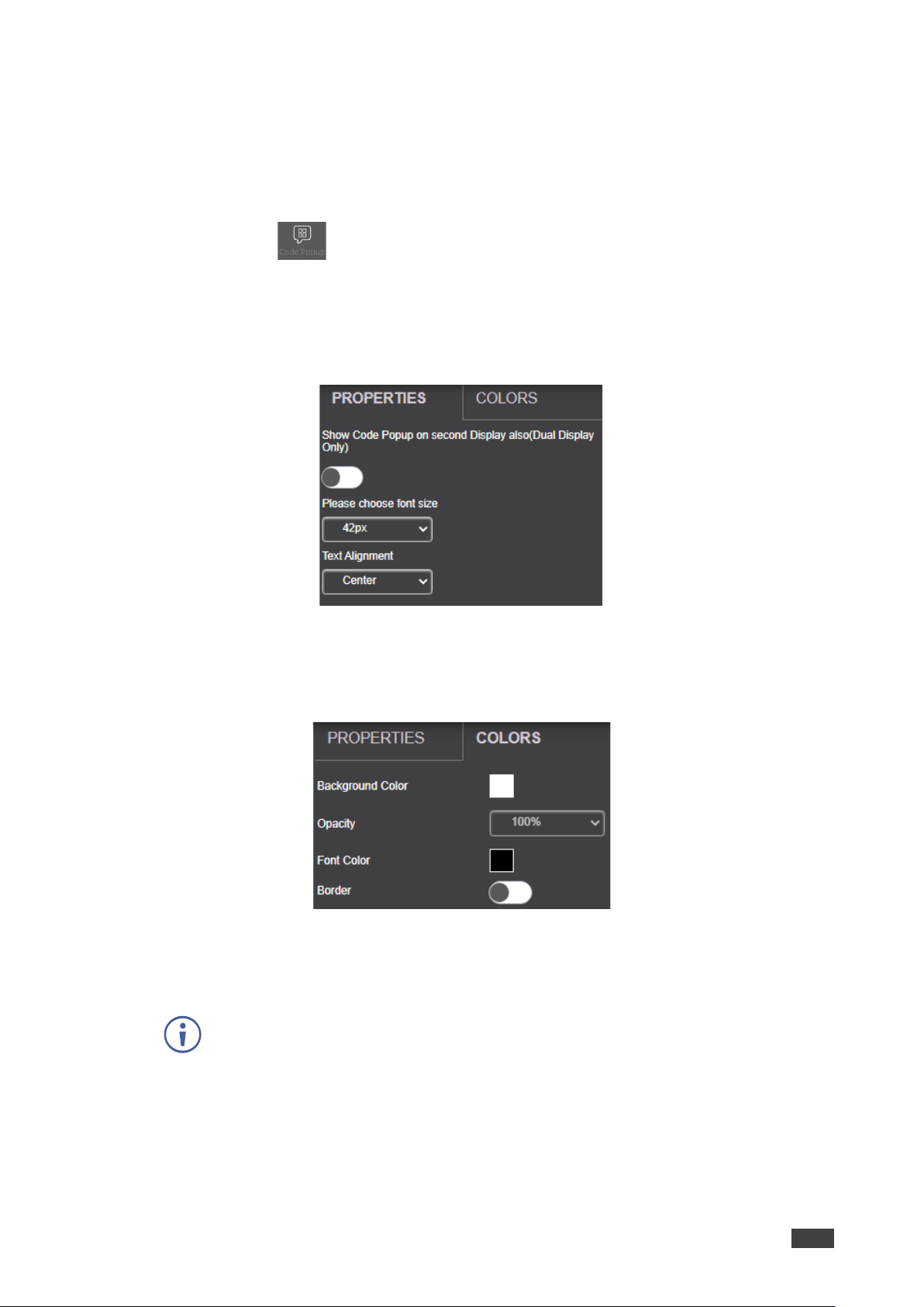
Adding Code Popup
the code popup controls the popup containing the room code, seen when a participant is
trying to login.
To add the code popup:
1. Click and drag to the center area to add the Code Popup box and show it on the
main display.
The right pane displays all the properties associated with Code Popup.
2. Select PROPERTIES tab on the right-side pane to enter the code popup number and set
its properties:
a. Set the font size of Code Popup.
b. Select the text alignment.
3. Select the COLORS tab on the right-side pane:
a. Click Background Color to change the text box background color.
by default the background is set to None (transparent background).
b. Set the Opacity of the background (after setting a background color).
Note that if opacity is set to 10%, the textbox background color becomes
transparent on the main display.
c. Change the font color (white, by default).
d. Toggle border (enable or disable) to show border on the main display.
Kramer Electronics Ltd.
VSM on Cloud & VSM on Premises – Managing VIA
61
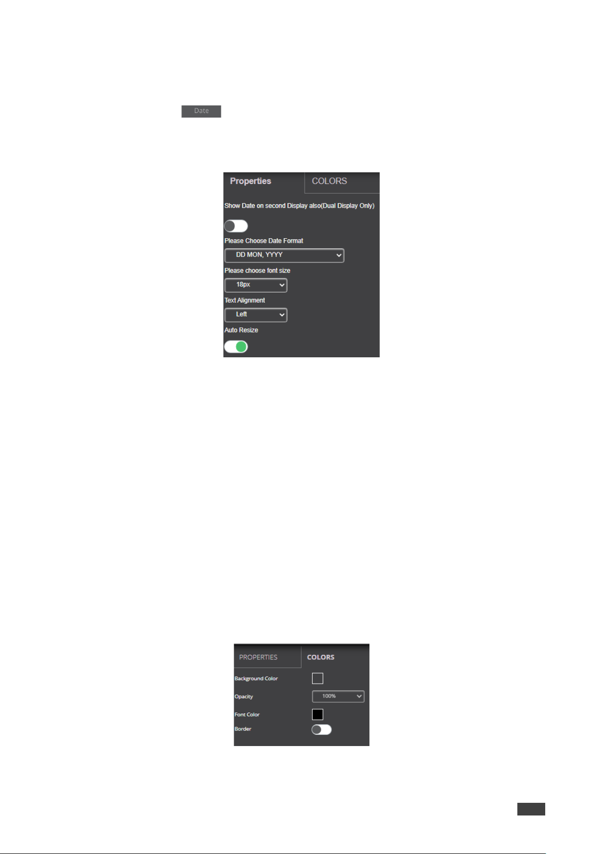
Adding Date
To add the date:
1. Click and drag onto the center area to add the date to the main display.
The right pane displays all the properties associated with Date.
2. Select PROPERTIES tab on the right-side pane to enter the date properties:
Figure 58: Date Color Tab
a. Move Show Room Code on second Display also (Dual Display Only) slider to ON
to display the date on the second display connected to the device.
b. Select the Date Format:
DD MON, YYYY – day, month and year.
MON DD, YYYY – month, day and year.
DD MON – Day and month only.
MON DD – month and day.
c. Set the font size.
d. Select the text alignment.
e. Auto resize toggle: move slider to ON to ensure that there are no cropped areas in
the displayed information. The border of the box is reset as per the size of the text.
This change is seen on the device and not while the template is still being created.
3. Select the COLORS tab on the right-side pane to set text colors:
Figure 59: Date Color Tab

Kramer Electronics Ltd.
VSM on Cloud & VSM on Premises – Managing VIA
62
a. Click Background Color to change the background color.
By default, the background is set to None (a transparent background).
b. Set the Opacity of the background (after setting a background color).
Note that if opacity is set to 10%, the textbox background color becomes
transparent on the main display.
c. Change the font color for text to appear in any other color.
d. Toggle border (enable or disable) to show border on the main display.
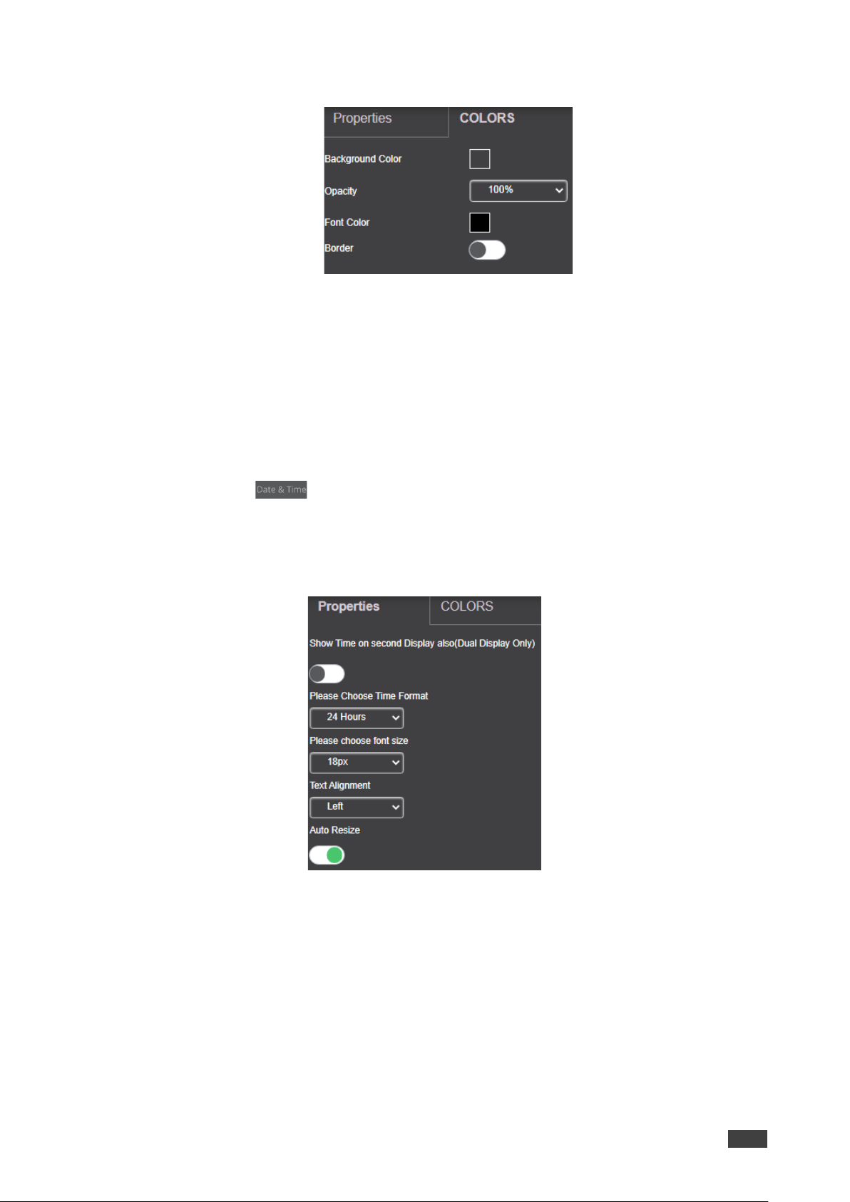
Adding Time
To add time:
1. Click and drag on to the gray area in the center to add the time box and show it
on main display.
The right pane displays all the properties associated with Time.
2. Select PROPERTIES tab on the right-side pane to enter the time properties:
Figure 60: Time Properties Tab
a. Move Show Room Code on second Display also (Dual Display Only) slider to ON
to display the time on the second display connected to the device.
b. Select the Time Format: 24 Hours or AM/PM.
c. Set the font size.
d. Select the text alignment.
e. Auto resize toggle: move slider to ON to ensure that there are no cropped areas in
the displayed information. The border of the box is reset as per the size of the text.
This change is seen on the device and not while the template is still being created.
Kramer Electronics Ltd.
VSM on Cloud & VSM on Premises – Managing VIA
63
3. Select the COLORS tab on the right-side pane:
Adding
a. Click Background Color to change the background color.
By default, the background is set to None (a transparent background).
b. Change the font color for text to appear in any other color.
c. Toggle border (enables or disables) to show border on the main display.
Adding Date & Time
To add date & time:
1. Click and drag onto the center area to add the date & time box and show it on
main display.
The right pane displays all the properties associated with Date & Time.
2. Select the PROPERTIES tab on the right-side pane.
a. Move Show Time on second Display also (Dual Display Only) slider to ON to
display the time on the second display connected to the device.
b. Select the Time Format: 24 Hours or AM/PM.
c. Set the font size.
d. Select the text alignment.
e. Auto resize toggle: move slider to ON to ensure that there are no cropped areas in
the displayed information. The border of the box is reset as per the size of the text.
This change is seen on the device and not while the template is still being created.
3. Select the COLORS tab on the right-side pane.
Kramer Electronics Ltd.
VSM on Cloud & VSM on Premises – Managing VIA
64
a. Click Background Color to change the background color.
By default, the background is set to None (a transparent background).
b. Set the Opacity of the background (after setting a background color).
Note that if opacity is set to 10%, the textbox background color becomes
transparent on the main display.
c. Change the font color.
d. Enable border to show border on the main display.
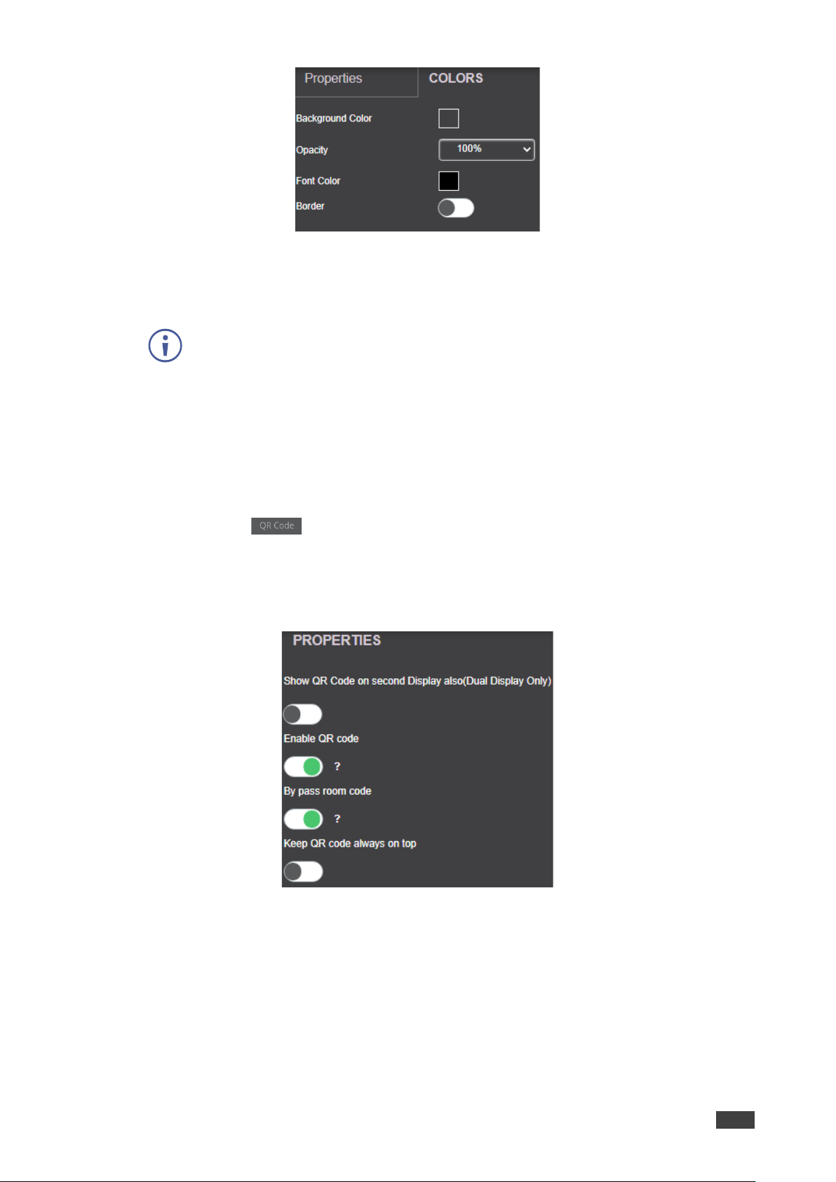
Adding Adding QR Code
To add a QR code:
1. Click and drag onto the center area to add a QR Code for mobile clients to scan
and login.
The right pane displays all the properties associated with the QR Code.
2. Select the PROPERTIES tab on the right-side pane:
a. Move Show QR Code on second Display also (Dual Display Only), slider to ON
to show the QR Code on both displays, when using dual displays.
b. Slide Enable QR code (to ON) and have the QR code appear on the main display.
c. Slide By pass room code (to ON) to have the clients scan and login to the device
without entering the room code.
d. Slide Keep QR code always on top (to ON) for the QR Code to appear on top
always.

Kramer Electronics Ltd.
VSM on Cloud & VSM on Premises – Managing VIA
65
Adding a Calendar
To add a calendar:
1. Click and drag onto the center area to add Upcoming Meetings box.
The right-side pane displays all the properties associated with the calendar.
2. Add the following properties.
a. Enter Upcoming meetings title.
b. Select the Time Format: 24 Hours or AM/PM.
c. Slide Show Title to ON to show the title of the meeting.
d. Slide Show Organizer to ON to show the organizer.
e. Select the No. of Records display, select the number of meetings, scheduled or
ongoing, to be displayed.
f. Set the font size.
Kramer Electronics Ltd.
VSM on Cloud & VSM on Premises – Managing VIA
66
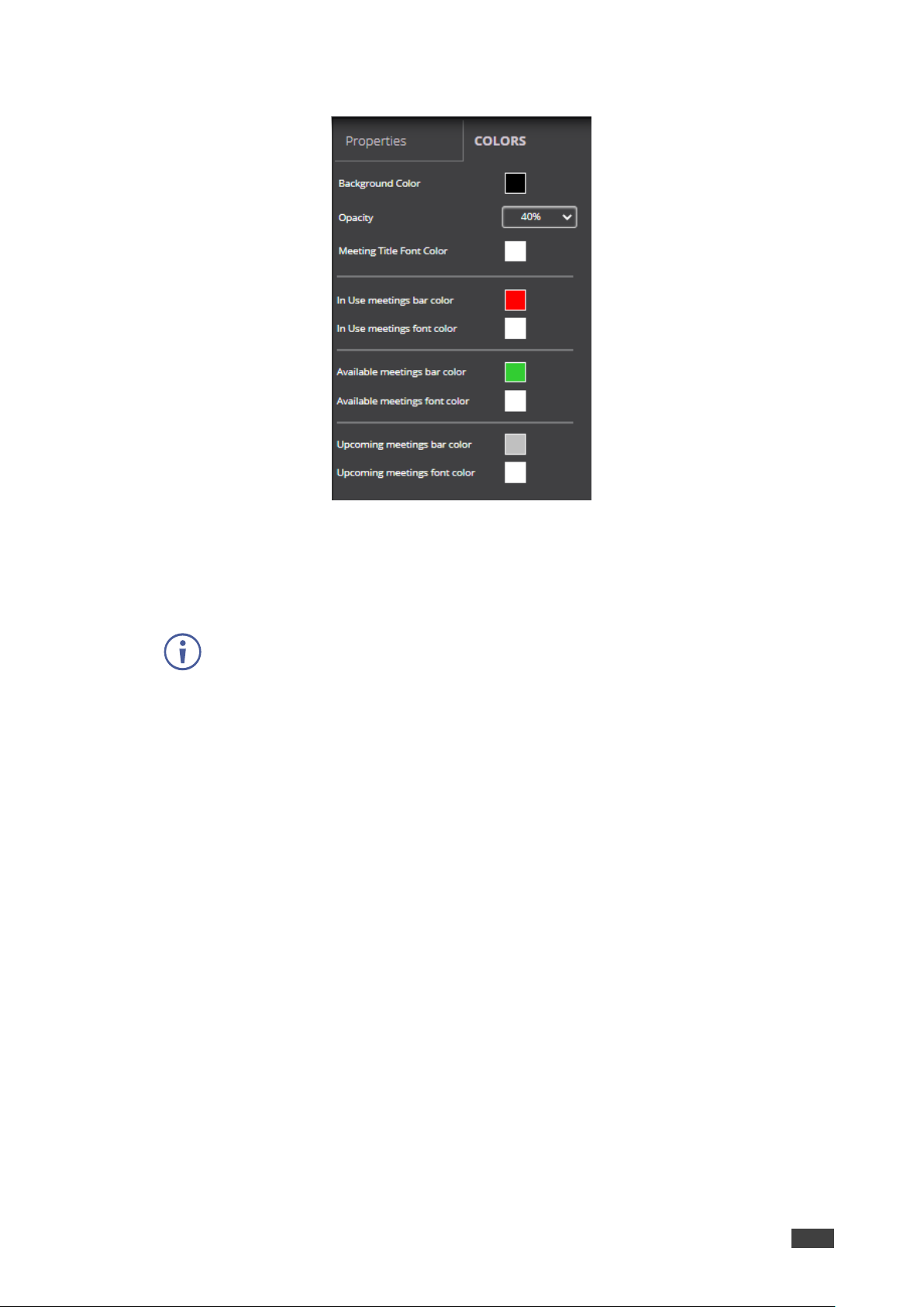
3. Select the COLORS tab on the right-side pane.
Figure 61: Calender Colors Tab
a. Click Background Color to change the background color.
By default, the background is set to None (a transparent background).
b. Set the Opacity of the background (after setting a background color).
Note that if opacity is set to 10%, the textbox background color becomes
transparent on the main display.
c. Select Meeting Title Font Color.
d. Select In Use meetings bar Color.
e. Select In Use meetings font Color.
f. Select Available meetings bar color – Select a color for the bar which marks when
a device or room is available for meetings.
g. Select Available meetings font color.
h. Select Upcoming meetings bar color.
i. Select Upcoming meetings font color.
4. Click Save.
Kramer Electronics Ltd.
VSM on Cloud & VSM on Premises – Managing VIA
67
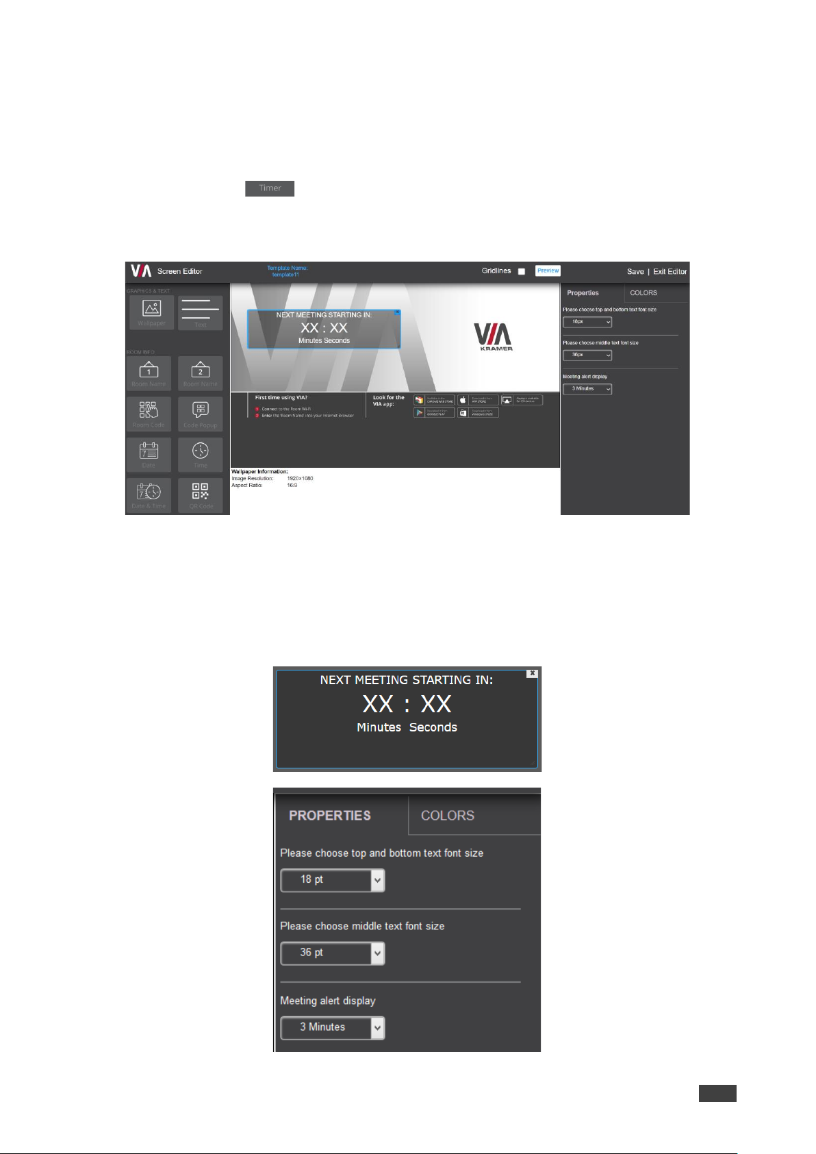
Adding Timer
The timer displays the time left before the next meeting.
To add the timer:
1. Click and drag onto the center area to add a timer for upcoming meetings and
show it on main display.
The right pane displays all the properties associated with the timer.
2. Select the PROPERTIES tab on the right-side pane:
a. Select the text font size.
b. Select the minutes and seconds (XX:XX) font size.
c. Set the Meeting alert display (for when the timer appears on main display before the
next meeting). The values are in minutes.

Kramer Electronics Ltd.
VSM on Cloud & VSM on Premises – Managing VIA
68
3. Select the COLORS tab on the right-side pane.
a. Click Background Color to change the background color.
By default, the background is set to None (a transparent background).
b. Set the Opacity of the background (after setting a background color).
Note that if opacity is set to 10%, the textbox background color becomes
transparent on the main display (40% by default).
c. Change the font color.
d. Enable border to show border on the main display.

Kramer Electronics Ltd.
VSM on Cloud & VSM on Premises – VSM Settings Management
69
VSM Settings Management
• Configuring VSM Home Page on page 69.
• Managing License Details on page 70.
• Viewing App Version Details on page 70.
• Defining VSM Settings on page 71.
Configuring VSM Home Page
VSM on Cloud & VSM on Premises enables modifying the design and functions of the home
page.
To configure a logo and logo URL:
1. Click VSM SETTINGS → Modify VSM Home Page.
2. Click the Show DNS Name in place of gateway name to Show DNS Name in place of
device name.
3. To change the logo, click Upload Logo and select a new logo.
4. If required, slide Auto redirect to login page to on (green) to redirect VSM to the black
login page after logging out of VSM.
By default, when logging out of VSM, the VSM home page appears.
5. To change the logo URL, in logo URL, enter logo URL and click Update.
6. Click Preview. An updated homepage preview appears.
7. Click Update.
8. To rollback changes in VSM homepage, click Reset to Default.

Kramer Electronics Ltd.
VSM on Cloud & VSM on Premises – VSM Settings Management
70
Managing License Details
Viewing VSM License
To view license details:
• Click VSM Management → License Details.
Figure 62: VSM License Details
Uploading VSM License (only for Cloud)
To upload a VSM license:
1. Save the VSM license to your server.
2. Click VSM SETTINGS → License Details.
3. Click Browse File.
4. Select the saved VSM license file from server.
5. Click Upload.
VSM license is uploaded.
Viewing App Version Details
To view App Version Details:
1. Login to the Administration Interface (see Accessing the Administration Interface
on page 9)
Figure 63: Viewing VSM Server Details
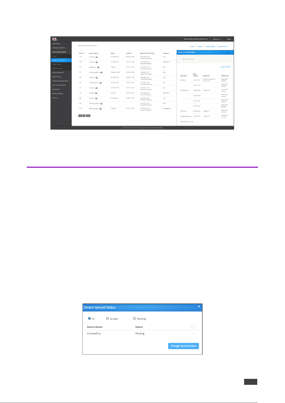
Kramer Electronics Ltd.
VSM on Cloud & VSM on Premises – VSM Settings Management
71
2. Click the VIA Server Version number on the Footer. The device version table appears.
Figure 64: VIA Server Version Details
3. If required, click Export to PDF.
The Version table downloads to an easy shareable PDF format.
Defining VSM Settings
Define VSM Settings such as VSM session timeout, captcha and VIA Discovery settings.
To define VSM settings:
1. Click VSM SETTINGS → Settings.
The DEVICES items appear.
2. Select DEVICES:
▪ Slide Auto Generated Device ID to on to automatically generate a gateway ID for
each VIA device that is added.
▪ Set business hours to define the time VSM alerts are sent.
▪ Slide Firebase Setting to on to….
3. Select VIA DISCOVERY, slide VIA Discovery Service on to enable VIA device
discovery.
▪ If on, click Check Synced Status to view device synced status.
Figure 65: VIA Discovery – Device Synced Status
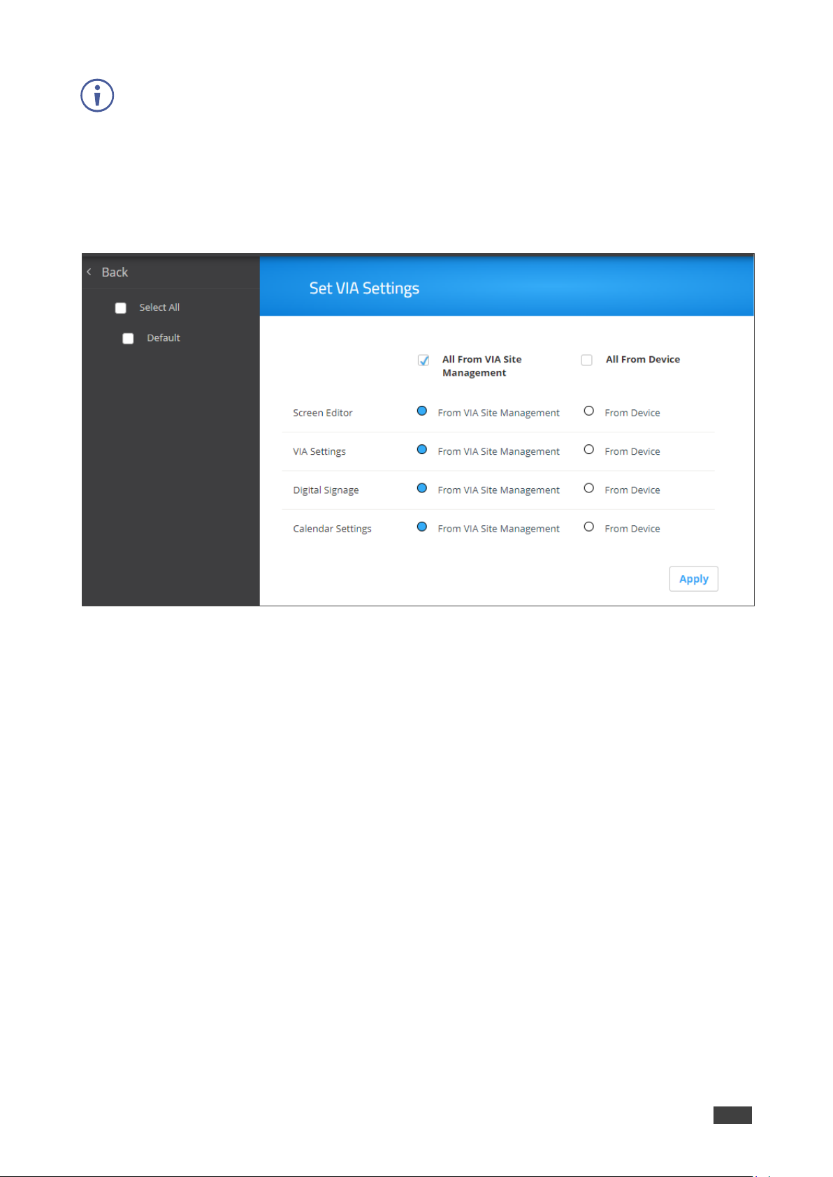
Kramer Electronics Ltd.
VSM on Cloud & VSM on Premises – VSM Settings Management
72
Gateways that have not yet been synced with VSM, show a “Pending” status. If the gateway
is connected, a checkbox appears.
▪ Select a checkbox and click Change Synced Status.
▪ The selected gateways are synced, and the status now shows “Synced”.
4. Select VIA DISCOVERY to set VIA settings:
▪ Click Set VIA Settings. The Set VIA Settings page appears.
Figure 66: Set VIA Settings Page
▪ For each of the VIA features, select which features to control from VSM or from the
device.
▪ Click Apply. (select all, default???)
5. Click WEB SESSION and select the session timeout.
6. To set auto log out session Frequency Alert, select time duration.
7. Click SECURITY:
▪ Slide Captcha to on/off to enable or disable captcha on VSM Login page.
▪ Select the password policy options for users to apply when selecting a password:
Use Alphanumeric characters.
Use at least one special character.
Use at least one capital letter.
Define minimum password length.
▪ Click Apply.

Kramer Electronics Ltd.
VSM on Cloud & VSM on Premises – Managing Firmware
73
Managing Firmware
VSM will push version 3.0/ 2.5/ 2.4 on device version 2.3.0418.960 and above.
• VIA allows schedule of firmware only after verifying that the device has enough space.
• Only .zip files can be uploaded, after upload the files turn into their respective .exe or
.rpm or .deb files for different models of the VIA.
• If the firmware download process is interrupted for some reason, the download will start
from the interrupted state rather than starting a fresh download.
Updating Firmware
You can upload the new firmware via VSM Management. The new uploaded Firmware on the
server is silently downloaded in the background on the VSM. Once download is complete,
authorized users receive Updated Firmware alerts.
Uploading the Firmware
To upload the Firmware:
1. Click FIRMWARE MANAGEMENT → Update Firmware. The Update Firmware page
appears.
Figure 67: Update Firmware Page
2. Click Update Firmware +. The Upload Firmware window appears.
Figure 68: Browse Firmware File
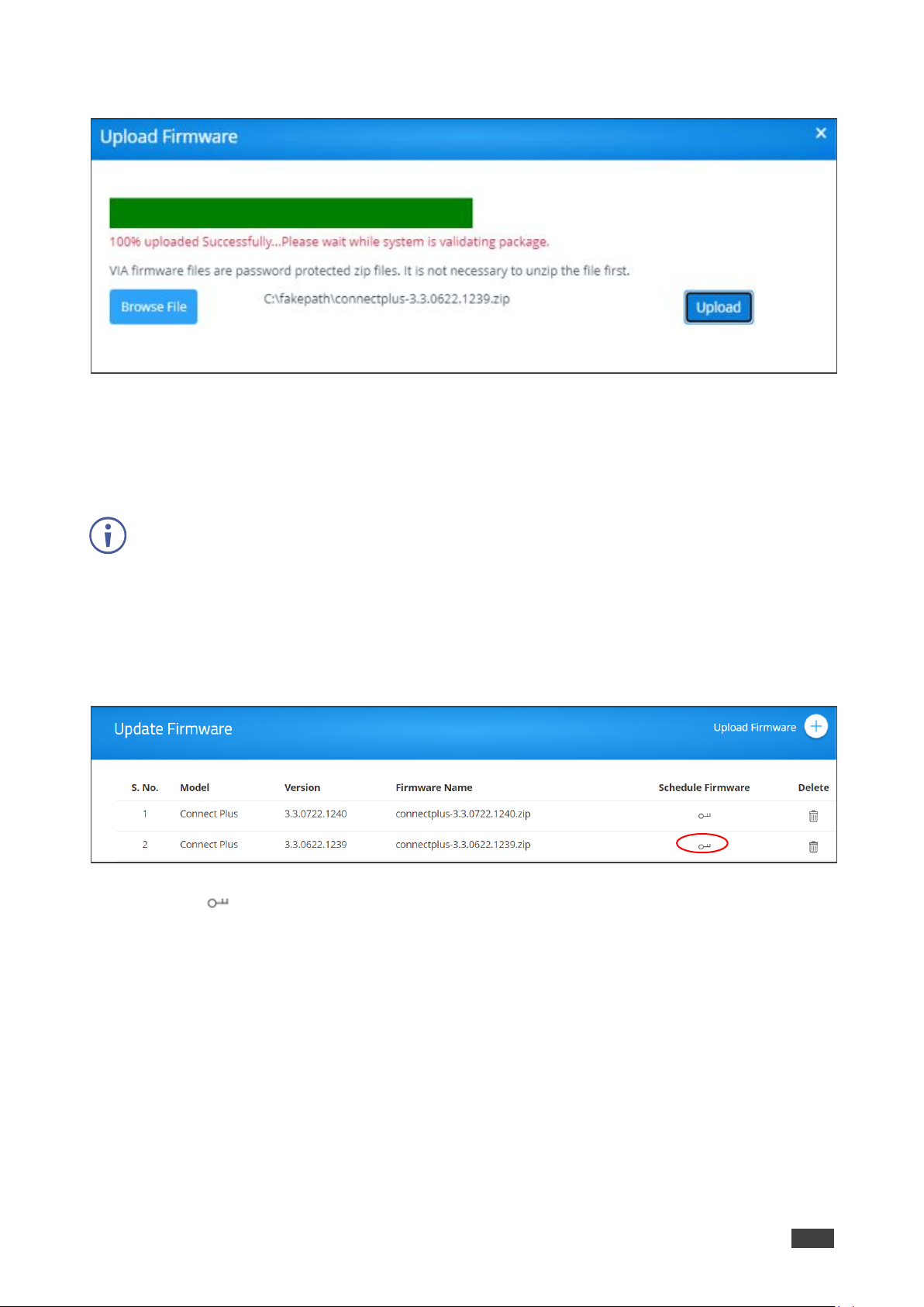
Kramer Electronics Ltd.
VSM on Cloud & VSM on Premises – Managing Firmware
74
3. Click Browse File and select the firmware (zip) file.
Figure 69: Firmware Uploading Pane
4. Click Upload.
The firmware is uploaded, and appears in the Upload firmware page.
5. Click Delete icon to delete firmware that is not scheduled for an update.
VIA firmware files are password protected ZIP files. It is NOT necessary to unzip the file first.
Scheduling a Firmware Update
To schedule firmware update:
1. Click FIRMWARE MANAGEMENT → Update Firmware.
Figure 70: Update Firmware Page
2. Click next to the relevant device.
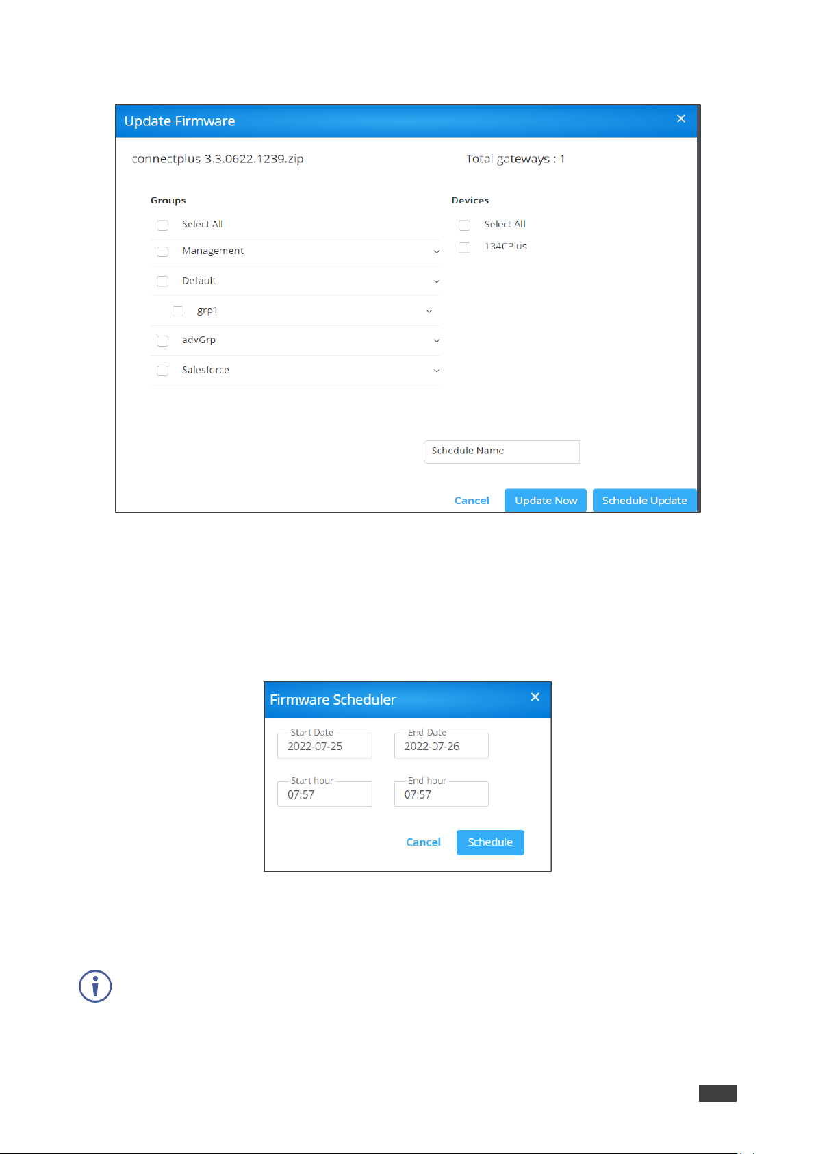
Kramer Electronics Ltd.
VSM on Cloud & VSM on Premises – Managing Firmware
75
3. Select respective Groups and Devices.
Figure 71: Update Firmware Pane
4. Select the gateway.
5. Enter Schedule Name Schedule Name field.
6. Click Update Now to update the firmware instantly or click Schedule Update to
schedule an update. When clicking Schedule Update, the Firmware Scheduler window
appears:
Figure 72: Firmware Scheduler
a. Select Start Date and End Date.
b. Select Start hour and End hour.
End time should be at least 6 hours later than start time.
c. Click Schedule.
Firmware update is scheduled and displays on Scheduled Updates page.
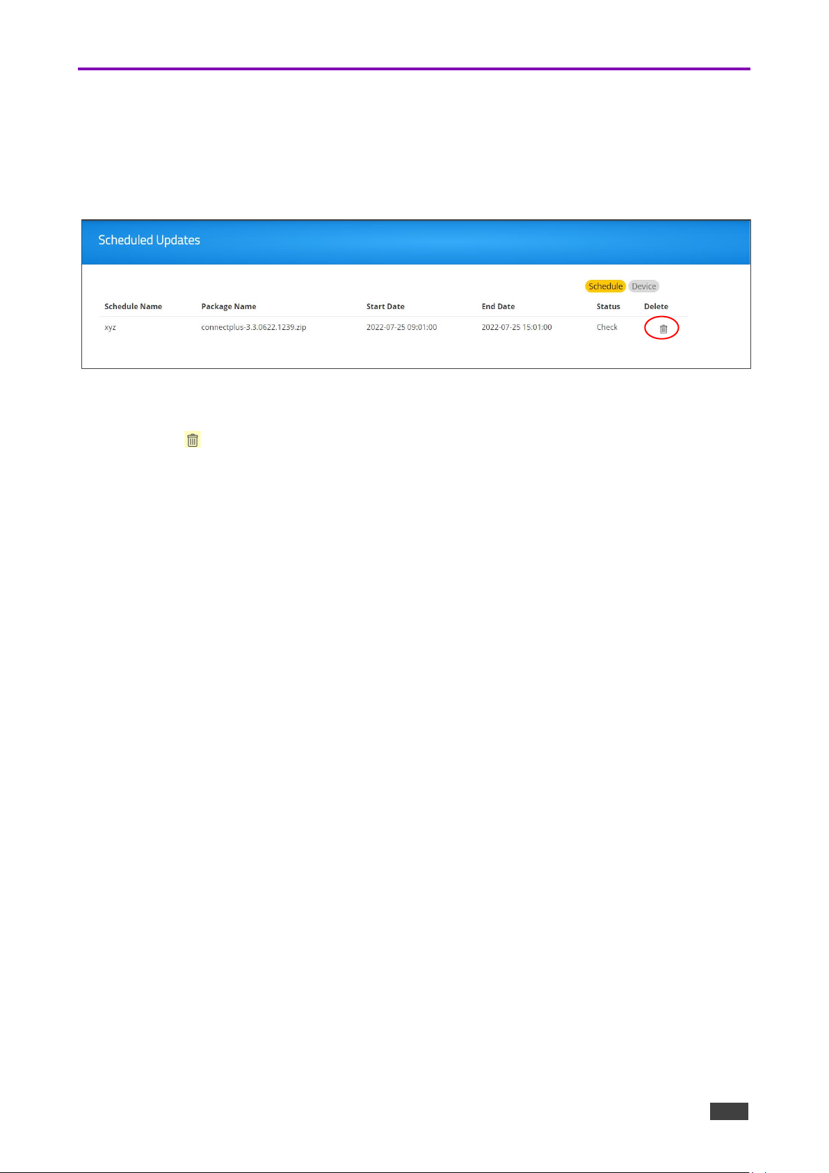
Kramer Electronics Ltd.
VSM on Cloud & VSM on Premises – Managing Firmware
76
Scheduling Updates
This option describes how to schedule firmware updates to the devices.
1. Click FIRMWARE MANAGEMENT → Scheduled Updates.
2. Click the respective schedule name to see details.
Figure 73: Scheduled Updates Page
3. Click Schedule to
4. Click to delete a specific device firmware update, next to the respective schedule
name.

Kramer Electronics Ltd.
VSM on Cloud & VSM on Premises – Managing Alerts
77
Managing Alerts
. The Alert List shows all the alerts that have been created on this VSM. Managing device
alerts via VSM includes the following actions:
• Users can edit and delete only the alerts created by them.
• For alerts created by other users, the only available options are to set them.
• Alert list shows the alert type and its threshold value, among other details.
• As per the rules of this threshold, the user receives an email if the threshold value is
exceeded.
▪ For CPU usage, alert emails are sent every 2 minutes.
▪ For Hard disk usage, email is sent every 6 hours.
▪ If VIA unit is unreachable, alert emails are sent every 15 minutes.
Adding an Alert
The alert list displays all the created and predefined alerts.note that VIA Unreachable and
New Firmware are default alerts.
To add an alert:
1. Click ALERT MANAGEMENT → Alert List. The Alert List page appears.
Figure 74: Alert List Page
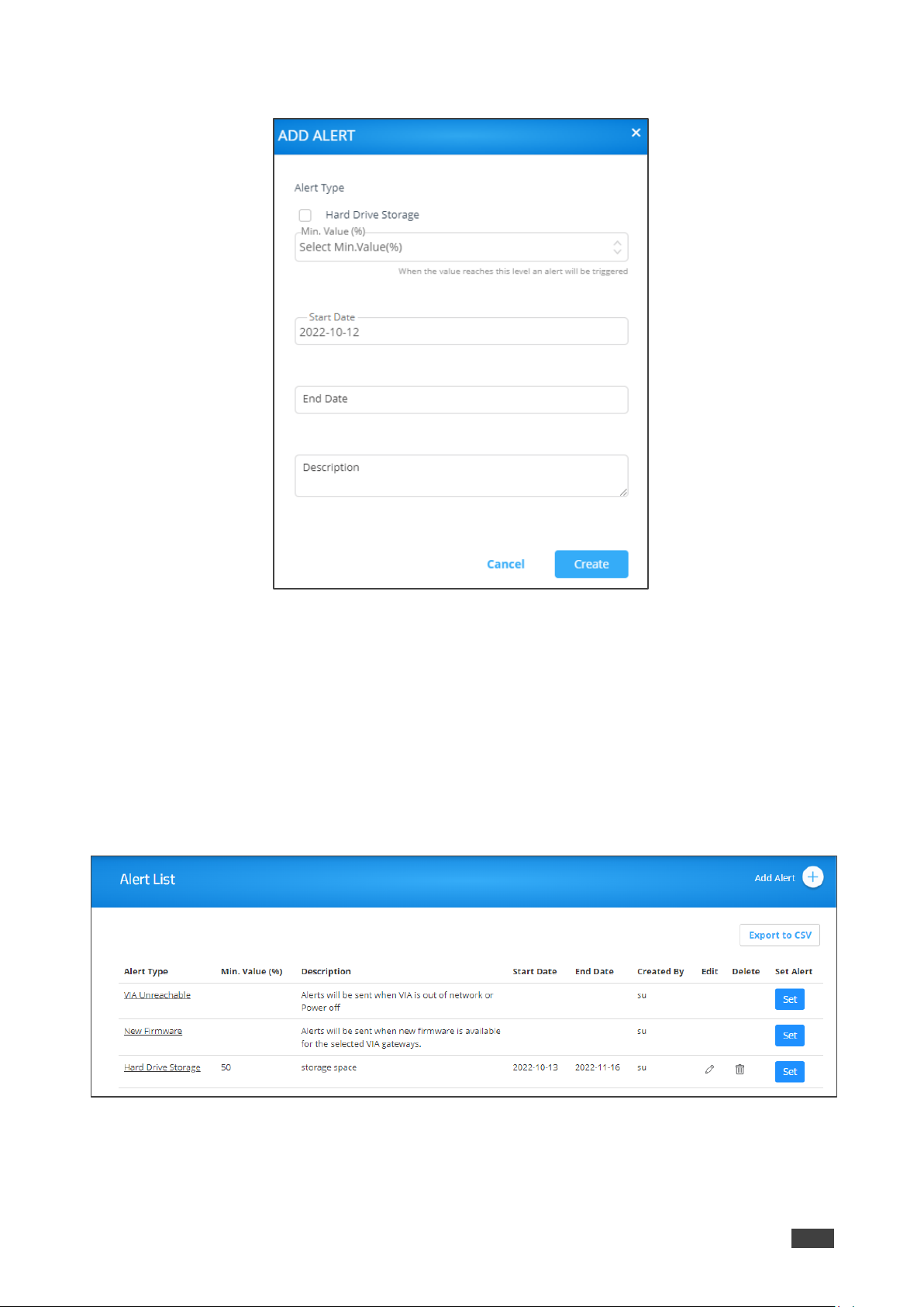
Kramer Electronics Ltd.
VSM on Cloud & VSM on Premises – Managing Alerts
78
2. Click Add Alert. The Add Alert window appears.
Figure 75: Add Alert Window
3. Under Alert Type, check Hard Drive Storage.
4. Select storage level minimum [%]. An alert is sent if storage drops below the selected
level.
5. Enter the alert Start Date.
6. Enter the alert End Date.
7. Enter the alert description.
8. Click Create. The alert is created. The Alert Type window appears.
Figure 76: New Alert Added

Kramer Electronics Ltd.
VSM on Cloud & VSM on Premises – Managing Alerts
79
Setting an Alert.
You can set either set a default or a created alert.
To set a default/created alert:
1. Click Set next to an alert in the Alert List page. The alert Type window appears.
Figure 77: Alert Type Window
2. Click Set against an alert type.
3. Under Groups, select a group of devices.
4. Under User, select the users who are to receive this alert type.
5. Under Devices, select the Destination devices for this alert type.
6. Click Set Alert.
The alert is set and enabled.
Managing Alert List
Each alert is assigned to all authorized users by default. An email is sent to the user which
can then activate or deactivate an alert for a specific duration.
To manage the alert list:
1. Click ALERT MANAGEMENT → Alert List. The Alert List page opens.
Figure 78: Alert List

Kramer Electronics Ltd.
VSM on Cloud & VSM on Premises – Managing Alerts
80
A User can only edit and delete the alerts created by him/her and can only use the set feature
on other user’s alerts.
2. To edit an alert:
▪ in the Alert List, click the Edit icon.
▪ Update the required field.
▪ Click Update.
3. To delete an alert, in the Alert List page, click the Delete icon.
4. Under Alert Type, to see alert details, click a specific alert. The alert applied to the
respective users and devices appears.
Figure 79: Alert Details Window
▪ Select a device and click Delete to stop receiving alerts from this device.
Suppressing an Alert
When an alert is sent to users, they receive an alert email with a link.
Figure 80: Alert Email
The users can then click the link in the email to activate or deactivate the alert page.
To suppress an alert:
1. Click the link in the alert email that you have received.
2. Inside the form field, click Alert End Date Time.
3. Select a date and time.
4. Click Add to suppress the alert until the selected date and time. Alerts stop coming the
moment you click Add.
5. Click Reset to clear the field and select a new date and time.

Kramer Electronics Ltd.
VSM on Cloud & VSM on Premises – Managing Alerts
81
Configuring SMTP
This feature is used to configure the email account with the SMTP server to receive alerts.
To configure SMTP:
1. Click ALERT MANAGEMENT -> SMTP Configuration.
SMTP configuration tab appears
Figure 81: SMTP Configuration Tab
2. In SMTP Configuration, enter the information into all fields.
3. Click Save.
4. To check validity of the link, click Mailer Auth.
The SMTP configuration success message appears.
Figure 82: SMTP Configuration Message
5. To test email validity, click Test Mail.
6. To reset the configuration, click Reset.
7. To update a configuration, click Update.

Kramer Electronics Ltd.
VSM on Cloud & VSM on Premises – Managing Alerts
82
Managing an Instant Alert Message
Using this option user can add alerts.
To manage the instant alert message:
1. Click ALERT MANAGEMENT → Instant Alert.
2. Click Add Alert.
Figure 83:Instant Alert Message
3. In the Create field, enter the Instant Alert Message to flash across all device screens
once activated.
4. Click Create.
5. Click an Instant Alert Message The set alert window appears, and the Instant Alert
Message can be configured.
Figure 84: Setting Alert Window
6. Perform the following actions:
a. Under Groups, select a device group.
b. Under Destination, select devices.
c. Select flash duration (the time the alert stays on) from the list.
d. Check Blinking for the alert to flash.
e. Click Send Alert to send an alert to the all list all the devices instantaneously. you
can click the alert message to view devices which are to receive this alert.

Kramer Electronics Ltd.
VSM on Cloud & VSM on Premises – Managing Recording
83
Managing Recording
Download, edit and delete a recording.
you can delete a selected recording from VSM. Before deleting you need to add the recording
devices to the VSM.
To Manage recording list:
1. Click RECORDING. The recording list appears.
2. Click Download on the selected row to download a recording.
3. Click Edit on the selected row to edit the recording description.
4. Click Delete on the selected row to delete the recording.
• Managing Content on page 84.
• Managing Templates on page 92.
• Managing Campaign Editor on page 94.
• Scheduling a Campaign on page 97.
• Managing Fonts on page 100.

Kramer Electronics Ltd.
VSM on Cloud & VSM on Premises – Digital Signage
84
Digital Signage
VSM enables configuring digital signage on any VIA Device. The Digital Signage feature
enables using VIA to display dynamic content and information on the main display when there
is no meeting in progress. Use a predefined template or create your own display configuration
with up to three frames of content that appear simultaneously. Then, schedule campaigns
(contact configurations) to run automatically at specific dates and times.
this section describes the following actions:
• Managing Content on page 84.
• Managing Templates on page 92.
• Managing Campaign Editor on page 94.
• Scheduling a Campaign on page 97.
• Managing Fonts on page 100.
Managing Content
VSM enables creating a library of media content to to use via digital signage. The types of
media that can be displayed are:
• Web URL – Live web page.
• Scroller – Scrolling text, custom text message that scroll across the screen.
• Media (Image) – Static image with the following allowed file extensions: jpg, jpeg, bmp,
gif and png.
• Media (Video) – Video with the following allowed file extensions: avi, mpeg, wmv, mpg,
mov, vob, mkv, mp4 and m4v.
• RSS – Live RSS feed.

Kramer Electronics Ltd.
VSM on Cloud & VSM on Premises – Digital Signage
85
To create and upload digital signage media:
1. Click DIGITAL SIGNAGE > Manage Content on the navigation pane. The Manage
Content page appears.
Figure 85: Manage Content Page
2. Create and upload media, as required:
▪ Adding Web URL on page 86.
▪ Creating Scrolling Text on page 87.
▪ Uploading Media Files on page 88.
▪ Adding RSS Feed on page 90.
3. Once created, you can perform the following actions:
▪ Click Scroller/RSS/Web URL/Media to filter the content by media type or click All to
view all media types.
▪ Click to preview the content.
▪ Click to download the content (video media type only).
▪ Click to edit the content (for Web URL, RSS and Scroller media types).
▪ Click to delete the selected media.
Media type is created and managed.
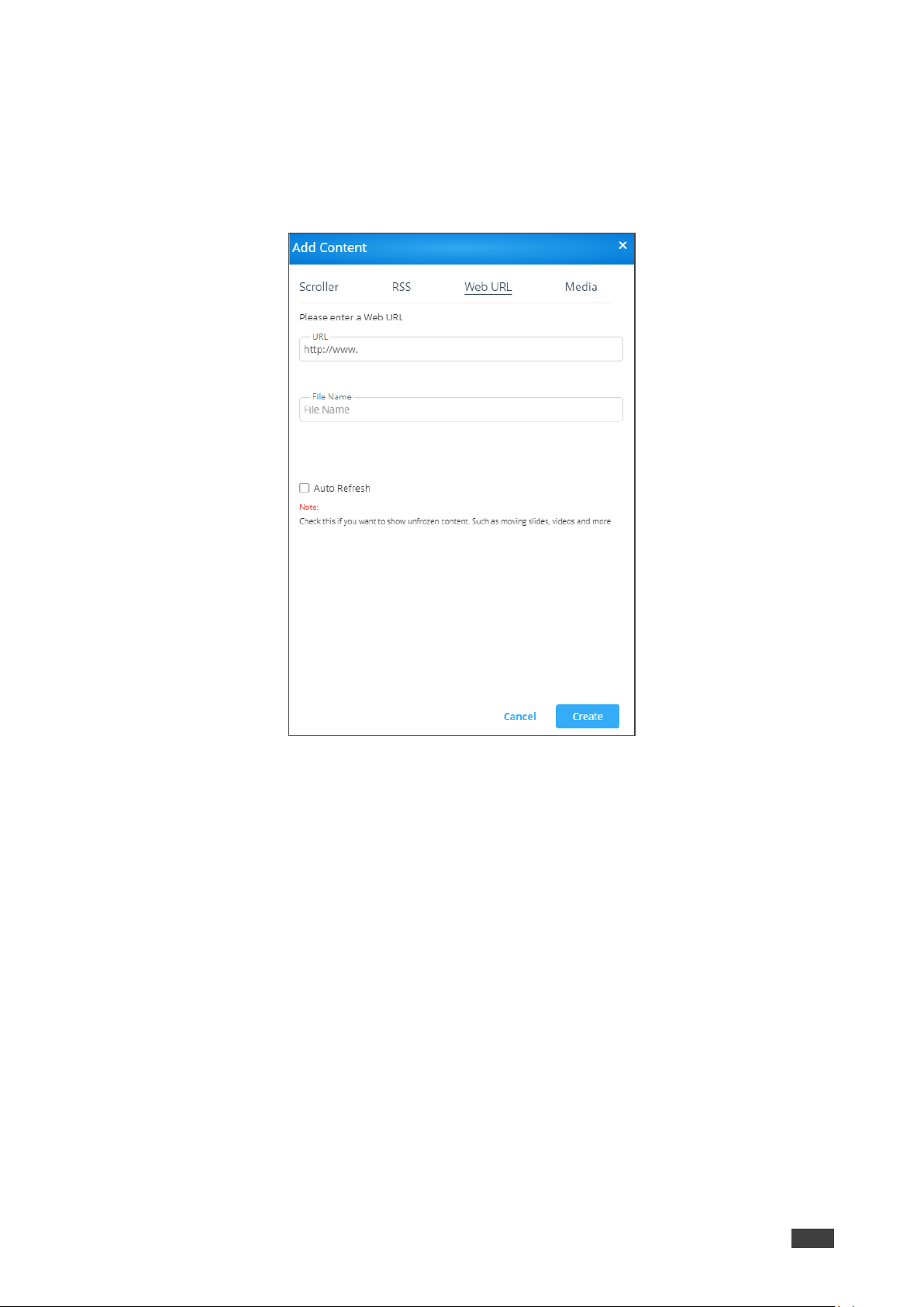
Kramer Electronics Ltd.
VSM on Cloud & VSM on Premises – Digital Signage
86
Adding Web URL
To add Web URL, to the Manage Content page:
1. Click Add Content and then Web URL.
The Web URL window appears.
Figure 86: Web URL Window
2. Enter the URL address and the File Name and click Create. The new URL is added to
the Existing Media list.
3. Set Auto Fresh check box as follows:
▪ Check Auto Refresh to display a URL with dynamic content.
▪ Clear Auto Refresh to display a URL as a static page.
4. Click Create.
URL content is created.
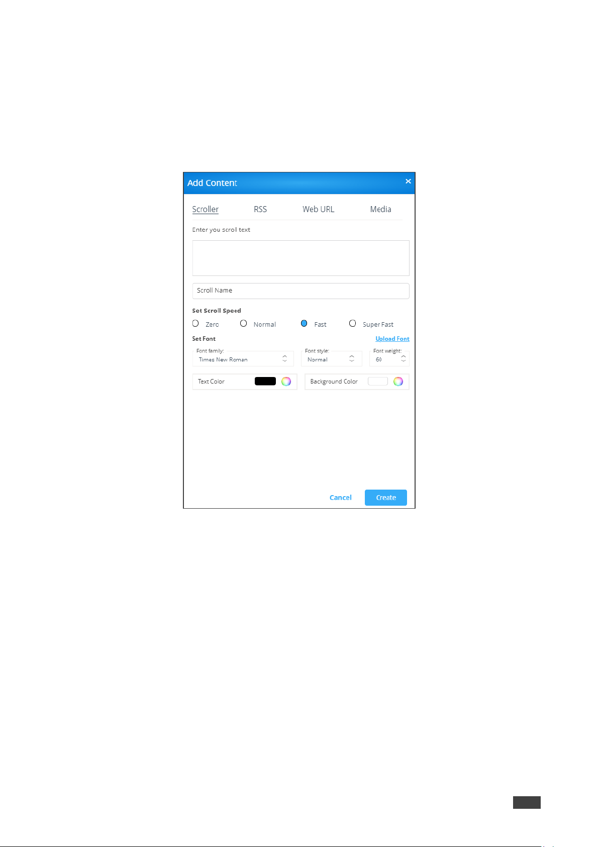
Kramer Electronics Ltd.
VSM on Cloud & VSM on Premises – Digital Signage
87
Creating Scrolling Text
To create scrolling text:
1. Click DIGITAL SIGNAGE > Manage Content on the navigation pane.
2. Click Add Content and then click Scroller.
The Scroller window appears.
Figure 87: Scroller Window
3. Enter the scroll text (for example, Welcome).
4. If required, enter the following variables into the text field:
▪ #airplayname# – Displays the airplay name.
▪ #roomname# – Displays the room name/code for joining into the meeting.
▪ #appass# – Displays the Access Point password.
▪ #apname# – Displays the Access Point name.
▪ #ipaddress1# –Displays the IP address for the primary network.
▪ #ipaddress2# – Displays the IP address for the second network, if in use.
5. Enter the Scroll Name (for example, Welcome).
6. Check the scrolling speed under Set Scroll Speed (for example, Fast). Select Zero to
create a static text display.
7. Under Set Font:
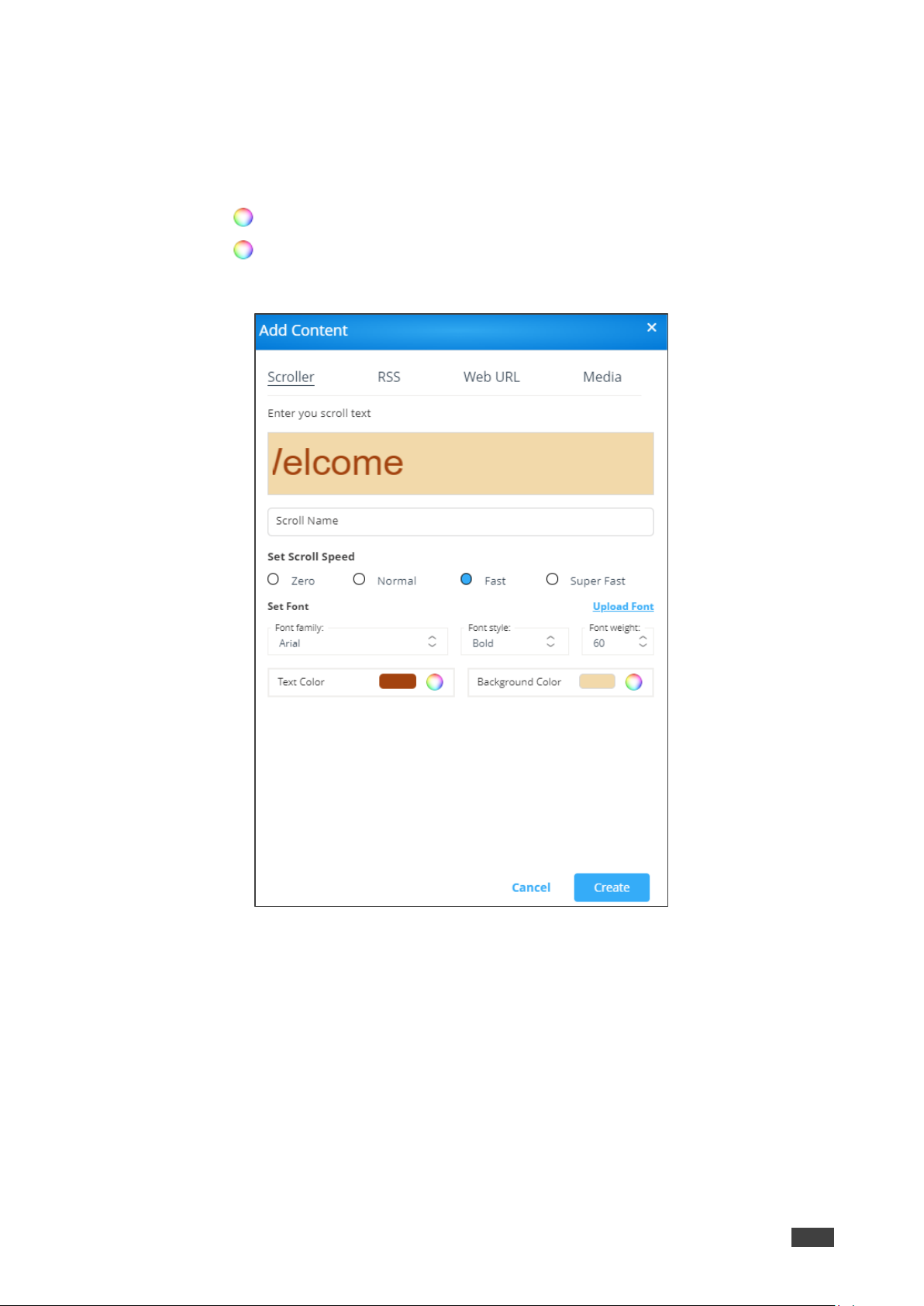
Kramer Electronics Ltd.
VSM on Cloud & VSM on Premises – Digital Signage
88
▪ Select the font type (under Font Family).
▪ Click Upload Font and follow the instructions to upload a new font type.
▪ Select the Font Style (Normal, Italic, Bold or Bold Italic).
▪ Select font size (under Font Weight).
▪ Click next to Text Color to select the text color.
▪ Click next to Background Color to select the background color.
The Scroller parameters are set:
Figure 88: Setting Scroller Content
8. Click Create.
The new scroller is added to the Existing Media list.
Uploading Media Files
To upload Media Files:
1. Click DIGITAL SIGNAGE > Manage Content on the navigation pane.
2. Click Add Content and then click Media.
The media window appears.

Kramer Electronics Ltd.
VSM on Cloud & VSM on Premises – Digital Signage
89
Figure 89: Media Window
3. Click Browse File.
A file browser window appears.
4. Select an image or video file and click Open.
5. Click Upload.
The file is added to the Existing Media list.
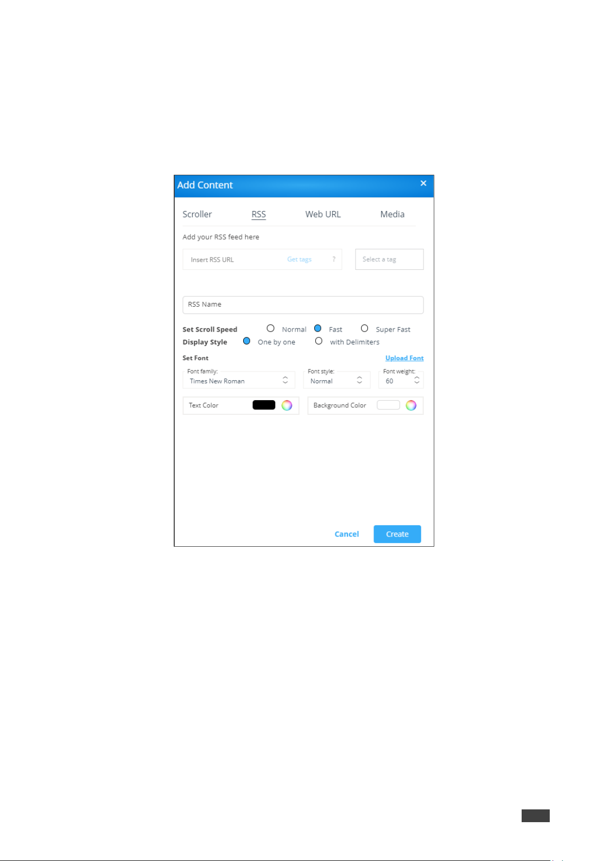
Kramer Electronics Ltd.
VSM on Cloud & VSM on Premises – Digital Signage
90
Adding RSS Feed
To add RSS Feed:
1. Click DIGITAL SIGNAGE > Manage Content on the navigation pane.
2. Click Add Content and then click RSS.
The RSS window appears.
Figure 90: RSS Window
3. Enter the RSS feed URL address into the Insert RSS URL text box.
4. Click Get tags. The Select a tag drop-down list appears.
5. Under the RSS Name, enter the RSS name.
6. Check the scrolling speed under Set Scroll Speed (for example, Fast).
7. Select the Display style (either One by one or with Delimiters.
8. Under Set Font:
▪ Select the font type (under Font Family).
▪ Click Upload Font and follow the instructions to upload a new font type.
▪ Select the Font Style (Normal, Italic, Bold or Bold Italic).
▪ Select font size (under Font Weight).

Kramer Electronics Ltd.
VSM on Cloud & VSM on Premises – Digital Signage
91
▪ Click next to Text Color to select the text color.
▪ Click next to Background Color to select the background color.
9. Click Create. The RSS feed is added to the Existing Media list.
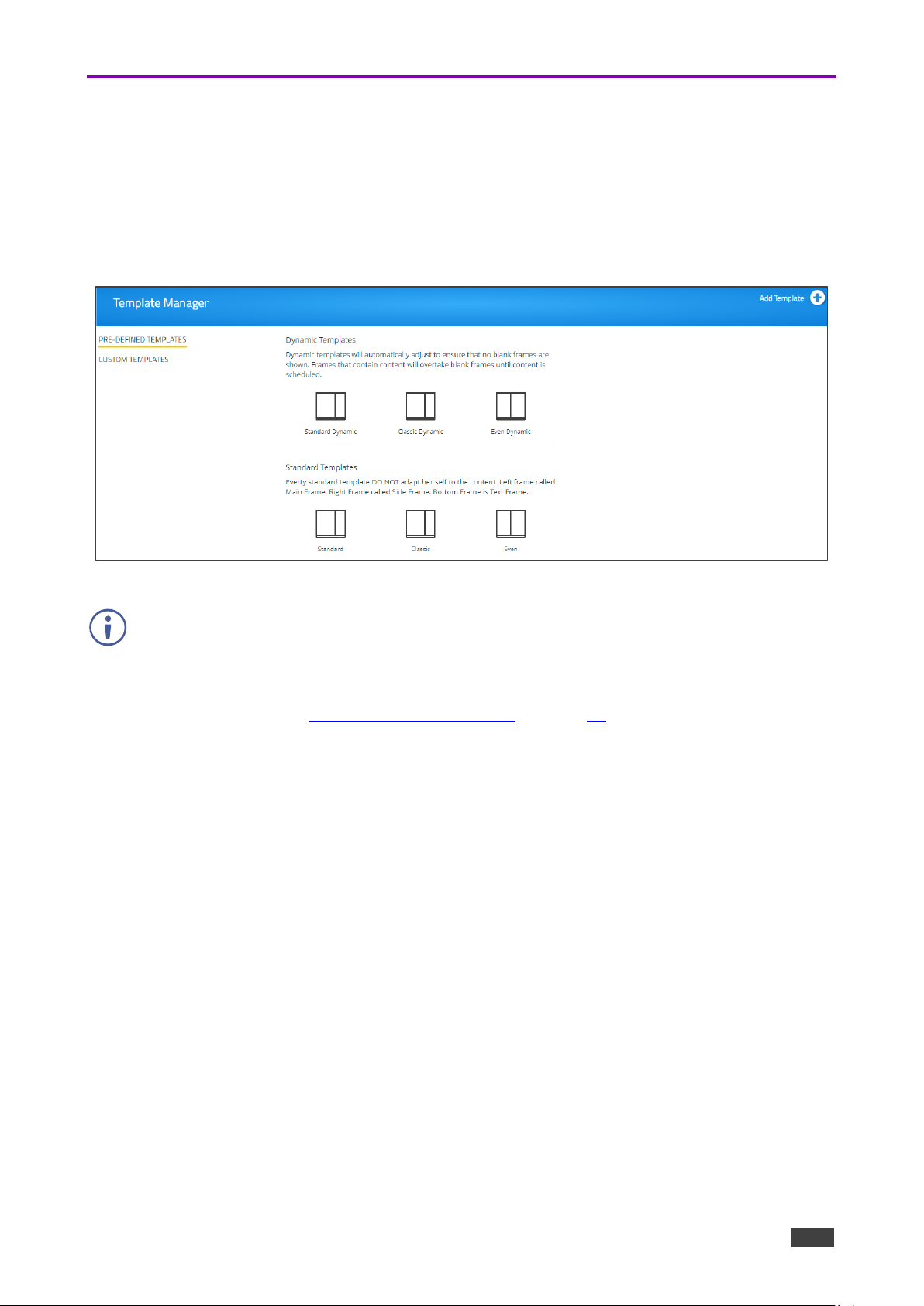
Kramer Electronics Ltd.
VSM on Cloud & VSM on Premises – Digital Signage
92
Managing Templates
VIA Campus enables you to preview, edit, delete and add digital signage templates.
To add a digital signage template:
1. Select DIGITAL SIGNAGE > Template Manager on the navigation pane.
The Template Manager page appears.
Figure 91: Template Manager Page
The Pre-Defined Templates tab shows Dynamic and Standard templates. Dynamic
templates automatically adjust to the content, to ensure that no blank frames are shown.
Standard Templates DO NOT adapt to the content.
You can select and use the predefined templates when creating a campaign via the
campaign editor (see Managing Campaign Editor on page 94).

Kramer Electronics Ltd.
VSM on Cloud & VSM on Premises – Digital Signage
93
2. Click Add Template. The Add Template window appears.
Figure 92: Add Template Window
3. Enter the template name to the Template Name text box.
4. Drag and drop box Frame1 to the display area on the left side.
Figure 93: Add Template Window
The frame moves to the display area.

Kramer Electronics Ltd.
VSM on Cloud & VSM on Premises – Digital Signage
94
5. Drag the box to move and resize it. Alternatively, you can use Frame 1 Properties to
resize and relocate it.
6. in the same way, you can drag and resize Frame2 and Frame 3.
You do not have to use all 3 frames.
7. Check Audio to play audio from a selected frame.
8. Click Save.
9. Select Custom Templates.
The new template is added and appears in the Custom Template Manager list.
A list of saved templates appears.
Figure 94: Custom Template List
10. For each created template, you can perform the following actions:
▪ Click to preview a selected template.
▪ Click to edit a selected template.
▪ Click to delete a selected template.
A custom template is created and managed.
Managing Campaign Editor
The Campaign editor enables creating, editing or deleting a campaign.

Kramer Electronics Ltd.
VSM on Cloud & VSM on Premises – Digital Signage
95
To manage the campaign editor:
1. Click Digital Signage >>Campaign Editor.
The create campaign page appears.
Figure 95: Create Campaign Page
2. Click Add Campaign to create a new campaign. The Campaign Editor window appears.
Figure 96: Campaign Editor Window

Kramer Electronics Ltd.
VSM on Cloud & VSM on Premises – Digital Signage
96
3. On the left side, select a template (a system or custom template), for example Standard
dynamic.
Figure 97: Selecting a Template
4. Under Content List, drag media content (scroller, RSS, web URL or media) to each
desired frame (see Managing Content on page 84).
You can filter the content list according to the different content types for ease of use.
Figure 98: Adding Media Content to Frames
You can add more than one media type to each frame.
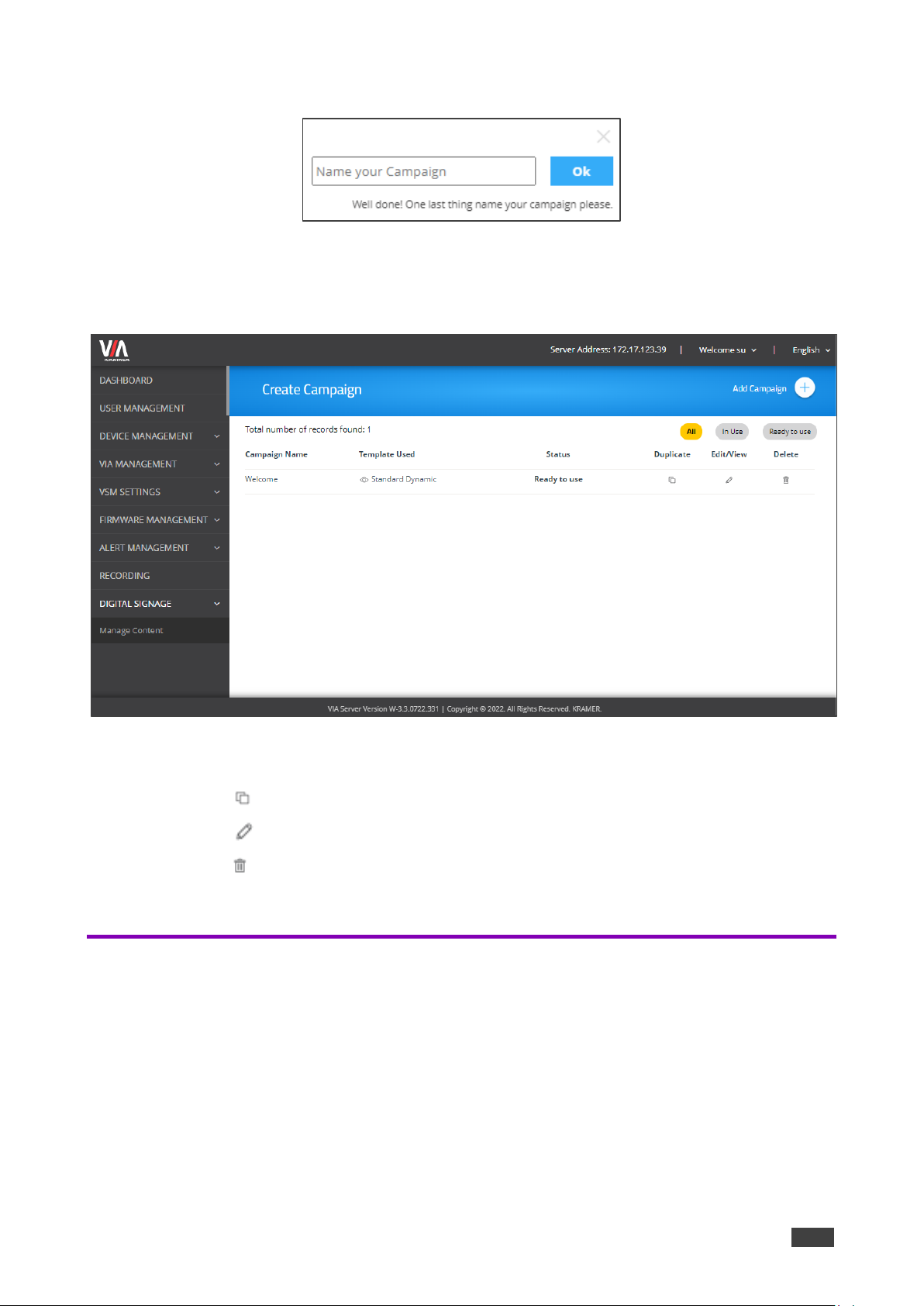
Kramer Electronics Ltd.
VSM on Cloud & VSM on Premises – Digital Signage
97
5. Click Save. A Name text box window appears.
Figure 99: Saving a Campaign
6. Enter the Campaign name.
7. Click Ok. The campaign name appears in the Create Campaign page.
Figure 100: Campaign Added to Campaign List
8. For each created campaign, you can perform the following actions:
▪ Click to duplicate a campaign (and then edit it).
▪ Click to edit a selected campaign.
▪ Click to delete a selected campaign.
A campaign is created and managed.
Scheduling a Campaign
The Schedule Campaign tab enables defining:
• What is displayed in each frame of a digital signage display.
• When a digital signage display appears.
To define a digital signage campaign:
1. Select DIGITAL SIGNAGE > Schedule Campaign.
The Schedule Campaign page appears.
 Loading...