

Page 1

Kramer Electronics, Ltd.
Preliminary
USER MANUAL
Model:
VS-88SDI
Page 2

Contents
i
Contents
1 Introduction 1
2 Getting Starte d 1
2.1 Quick Start 2
3 Overview 3
4 Your VS-88SDI 8x8 SDI Matrix Switcher 4
4.1 Using the IR Transmitter 7
5 Installing the VS-88SDI in a Rack 8
6 Connecting the VS-88SDI 9
6.1 Connecting the RS-232 Port 10
6.1.1 Determining the Machine Number 11
6.1.2 Setting the DIP-Switches 11
6.2 Connecting a PC or Controller to the RS-485 Port 12
6.2.1 Setting the Address Switches 12
6.2.2 Setting the Line Termination 13
6.3 Factory Reset 13
6.4 Switching Genlocked Video Sign als 13
6.5 Connecting the Ethernet Port 13
6.5.1 Connecting the ETHERNET Port Directly to a PC (Crossover Cable) 14
6.5.2 Connecting the ETHERNET Port via a Network Hub (Straight-Through Cable) 15
6.6 Configuring the Ethernet Port 15
6.7 Controlling via the Ethernet Port 17
6.8 Using the Ethernet Reset Button 17
7 Operating the VS-88SDI 18
7.1 Operating the VS-88SDI from the Front Panel 18
7.1.1 Power On Display 18
7.1.2 Using the AT ONCE and CONFIRM Modes 18
7.1.3 Switching in the AT ONCE Mode 18
7.1.4 Toggling Between Modes 19
7.1.5 Switching in the CONFIRM Mode 19
7.1.6 Storing an Input/Output Configuration 19
7.1.7 Recalling an Input/Output Configuration 20
7.1.8 Locking the Front Panel 20
7.1.9 Switching Protocols 20
7.1.10 Indicating Errors 20
7.2 Using Serial Commands 21
7.3 Using the Infrared Remote Controller 21
8 Technical Specifications 21
9 Communication Parameters 22
10 Using the P3K Wizard 22
Page 3

KRAMER: SIMPLE CREATIVE TECHNOLOGY
Contents
ii
10.1 Changing the Device Parameters 22
10.2 Updating the VS-88SDI Firmware 25
11 Kramer Protocol 3000 26
11.1 Switching Protocols 26
11.2 Kramer Protocol 3000 Syntax 27
11.2.1 Host Message Format 27
11.2.1.1 Simple Command 27
11.2.1.2 Command String 27
11.2.2 Device Message Format 27
11.2.2.1 Device Long Response 27
11.2.3 Command Terms 28
11.2.4 Entering Commands 28
11.2.5 Command Forms 29
11.2.6 Command Chaining 29
11.2.7 Maximum String Length 29
11.2.8 Backward Support 29
11.3 Kramer Protocol 3000 Commands 30
11.3.1 Device Initiated Messages 30
11.3.2 Result and Error Codes 30
11.3.3 Basic Routing Commands 30
11.3.4 Preset Commands 31
11.3.5 Operation Commands 31
11.3.6 Machine Information Commands 31
11.3.7 Identification Commands 32
11.3.8 Network Setting Co mmands 32
12 Hex Table (Protocol 2000) 33
13 Kramer Protocol 2000 34
Figures
Figure 1: VS-88SDI 8x8 SDI Matrix Switcher 5
Figure 2: Connecting the VS-88SDI 8x8 SDI Matrix Switcher 10
Figure 3: DIP-Switch Settings 12
Figure 4: Local Area Connection Properties Window 14
Figure 5: Internet Protocol (TCP/IP) Properties Window 15
Figure 6: Connect Screen 16
Figure 7: Device P r operties Screen 17
Figure 8: P3K Wizard Screen 23
Figure 9: Connect Window 24
Figure 10: Device Properties Window 25
Page 4

Contents
iii
Tables
Table 1: Front Panel VS-88SDI 8x8 SDI Matrix Switcher 6
Table 2: Rear P anel V S-88SDI 8x8 SDI Matrix Switcher 6
Table 3: Machine # DIP-Switch Settings 11
Table 4: DIP-Switch Settings 12
Table 5: Genlock Settings 13
Table 6: VS-88SDI Technical Specifications 21
Table 7: Communication Parameters 22
Table 8: VS-88SDI Hex Codes for Switching via RS-232/RS-485 33
Table 9: Protocol Definitions 34
Table 10: Instruction Codes for Protocol 2000 35
Page 5

Introduction
1
1 Introduction
Welcome to Kramer Electronics! Since 1981, Kramer Electronics has been
providing a world of unique, creative, and affordable solutions to the vast
range of problems that confront the video, audio, presentation, and
broadcasting professional on a daily basis. In recent years, we have
redesigned and upgraded most of our line, ma king the best even b etter! Our
1,000-plus different models now appear in 11 groups
1
Thank yo u for purchasing the Kra mer VS-88SDI , which is ideal for:
that are clearly
defined by function.
• Professional broadcasting and production studios
• Presentation applicatio ns
The package includes the following items:
• The VS-88SDI
• RC-IR3 remote control (with manual)
• Power cord
2
• This user manual
and rack “ears”
3
2 Getting Started
We recommend that you:
• Unpack the equipment carefully and save the original box and
packaging materials for possible future shipment
• Review the contents of this user manual
• Use Kramer high performance high-resolution cables
4
1 GROUP 1: Distribution Amplifiers; GROUP 2: Switchers and Matrix Switchers; GROUP 3: Control Systems;
GROUP 4: Format/Standards Converters; GROUP 5: Range Extenders and Repeaters; GR OUP 6: Specialty AV Products;
GROUP 7: Scan Converters and Scalers; GROUP 8: Cables and Connectors; GROUP 9: Room Connectivity;
GROUP 10: Accessories and Rack Adapters; GROUP 11: Sierra Products
2 We recommend that you use only the power cord supplied with this device
3 Download up-to-date Kramer user manuals from our Web site at http://www.kramerelectronics.com
4 The complete list of Kramer cables is on our Web site at http://www.kramerelectronics.com
Page 6
KRAMER: SIMPLE CREATIVE TECHNOLOGY
Getting Started
2
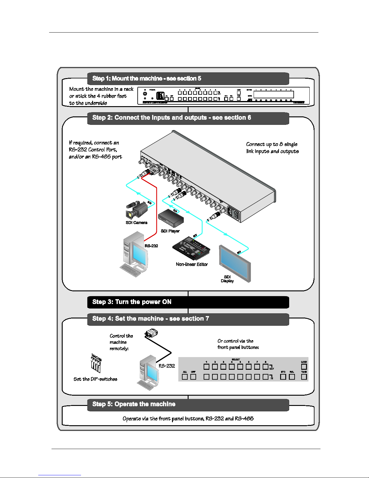
2.1 Quick Start
This quick start chart summarizes the basic setup and operation:
Page 7

Overview
3
3 Overview
The VS-88SDI is a high-performance matrix switcher for SDI signals. The
unit can switch up to 8 inputs to any or all of 8 outputs.
In particular, the VS-88SDI features:
• Operation of up to 540Mbps – enabling it to be used for standard
definition serial digital vid e o signals (SDI)
• SMPTE 259M, 344M, compliance and support for data rates of
540Mbps
• Cable equalization up to 350m for SD
1
• Reclocking and equalization on each input, storing and recalling
setups, and a TAKE button for the execution of multiple switches
all at once
signals
• The ability to switch genlo c ked video signals accord ing to the
timing of the genlock reference input. Switching according to the
bi-level or tri-level genlock input
2
The VS-88SDI is housed in a 19" 1U rack-mountable enclosure, and is fed
from a 100-240 VAC universal switching power supply. The unit c an be
controlled via the fro nt panel buttons or via:
according to SMPTE RP-168
• An infrar ed remote control transmitter
• An infrar ed remote extens ion cable transmitter
• Re motely, by RS-232 or RS-485 serial commands transmitted by a
PC, touc h s creen system, or other serial controller
• The Ethernet
• By default , the VS-88SDI is operated using the Kramer 3000
protocol (see section
7.1.9 for details of how to switch to Protocol
2000 and section
10.2 for the relevant protocol commands)
1 Standard Definition (SD) means an NT SC or PAL compatible video for mat, consistin g of 480 (for NTSC) or 576 (for P AL)
lines of interlaced video
2 The sources must be genlocked to the GENLOCK input in order to switch clearly
Page 8

KRAMER: SIMPLE CREATIVE TECHNOLOGY
Your VS-88SDI
4
To achieve the best performance:
• Use only good quality connection cables
1
• Avoid interference from neighboring electrical appliances that may
adversely influence signal quality and position your Kramer
VS-88SDI away from moistur e, excessive sunlight and dust
to avoid interference,
deterioration in signal q uality due to poor matching, and elevated
noise levels (often associa te d with low quality cables)
4 Your VS-88SDI
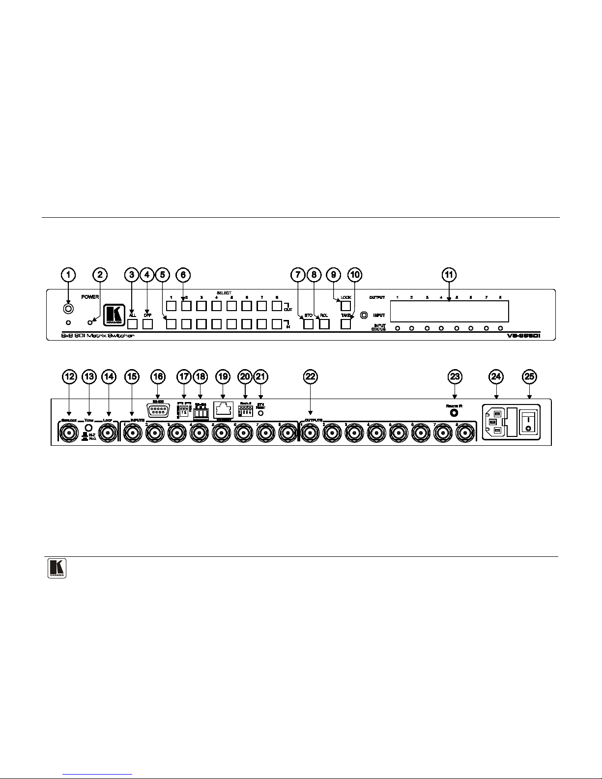
Figure 1, Table 1, and Table 2 define the VS-88SDI .
1 Available from Kramer Electronics on our Web site at http://www.kramerelectronics.com
Page 9
Your VS-88SDI
5
Figure 1: VS-88SDI
Page 10
KRAMER: SIMPLE CREATIVE TECHNOLOGY
Your VS-88SDI
6
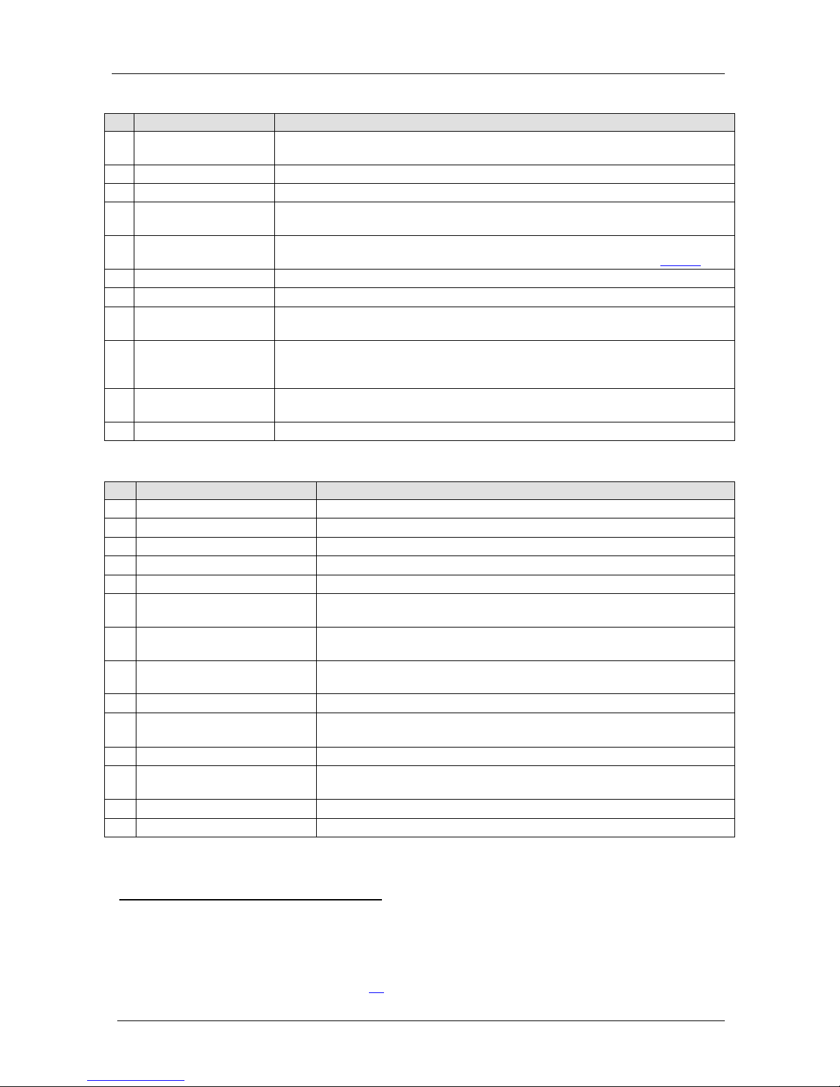
Table 1: Front Panel VS-88SDI
#
Feature
Function
1 IR Receiver The yellow LED is illuminates when receiving signals from the infrared remote
control transmit te r
2 POWER LED Illuminates when the unit is ON
3 ALL Button Pressing ALL followed by an INPUT button, conne c ts tha t i np ut to all outputs
4 OFF Button Pressing OFF+OUT disconnects that output from the inputs;
pressing OFF+ALL disconnects all the outputs
5 IN SELEC T Buttons Select the input to switch to the output;
long presses on buttons IN1 to IN5 change the genlock timing (see
Table 5 )
6 OUT SELECT Buttons Select the output to which the input is switched
7 STO (STORE) Button Pressing STO follo wed by an IN / OUT butt on sto res th e curr ent set ting
8 RCL (RECALL) Button Pressing the RCL button and the corresponding INPUT / OUTPUT key recalls a
setup from the non-volatile memory
9 LOCK Button A long press toggles activation/inactivation of the front pa nel butt ons ;
pressing LOCK+OUT2 selects Protocol 2000; pr essi n g LOCK +OUT3 selects
Protocol 3000
10 TAKE Button Pressing TAKE toggles the mode between the CONFIRM mode and the AT
ONCE mode (user confirmation per action is unnecessary)
11 7-segment Display Displays the selected input switched to the output (marked above each input)
Table 2: Rear Panel VS-88SDI
#
Feature
Function
12 GENLOCK BNC Connector Connects to the genlock source
13 TERM HI-Z/75Ω Pushbutton Press to terminate the genlock source (75Ω) or release for looping
14 LOOP BNC Connector Connects to the genlock connector of the next unit in the line
15 INPUT BNC Connectors Connects to the serial digital video sources
16 RS-232 9-pin D-sub (F) Port Connects to the PC or the remote controller
17 PROG/RS-485 TERM
DIP-switches
PROG DIP-switch enables microcontroller firmware upgrade
RS-485 TERM DIP-switch terminates the RS-485 line with a 120Ω load
18 RS-485 Terminal Block Port Pins B (-) and A (+) are for RS-485;
Pin G may be connected to the shie ld (if required)
19 ETHERNET RJ-45 Connecto r C onnects to the PC or other Serial Contr oller thr ough c o mputer networ king
LAN
20 MACH # DIP-switches DIP-switches 1-4 for setting the Machi n e Address of the unit
21 ETH RESET Button Press to re set t o factory default def inition s
1
22
:
IP number − 192.168.1.39, Mask – 255.255.0.0, Gateway – 0.0.0.0
OUTPUT BNC C on nec tors Connect to the serial digital video acceptors
23 REMOTE IR 3.5mm Mini Jack Connect to an ex te rna l IR re ceiver un it f or cont ro lling t he m achine via an I R
remote controlle r ( in stead of using th e front pa ne l I R rec eiver )
2
24 Power Connecto r wit h Fus e AC connector enabling power supply to the unit
25 Power Switch Turns the power to the unit ON and OFF
1 First disconnect the power cord and then connect it again while pressing the ETH Factory Reset button. The unit powers up
and loads its memory with the factory default definitions and erases all stored presets
2 Optional. Can be used instead of the front panel (built-in) IR receiver to remotely control the VS-88SDI (only if the internal
IR connection cable has been installed) (See section
4.1)
Page 11

Your VS-88SDI
7
7
4.1 Usi n g th e IR Transmitter
You can use the RC-IR3 I R transmitter to control the machine via the builtin IR receiver on the front panel or, instead, via an optional external IR
receiver
1
. The external IR receiver can be located 15 meters away from the
machine. This distance can be extended to up to 60 meters when used with
three extension cables
2
Before us ing the ext ernal IR receiver, be sure to arrange for your Kramer
dealer to insert the internal IR connection cable
11F
3
with the 3.5mm connector
that fits into the REMOTE IR opening on the rear panel. Connect the
external IR receiver to the REMOTE IR 3.5mm connector.
1 Model: C-A35M/IRR-50
2 Model: C-A35M/A35F-50
3 P/N: 505-70434010-S
Page 12
KRAMER: SIMPLE CREATIVE TECHNOLOGY
Installing the VS-88SDI in a Rack
8
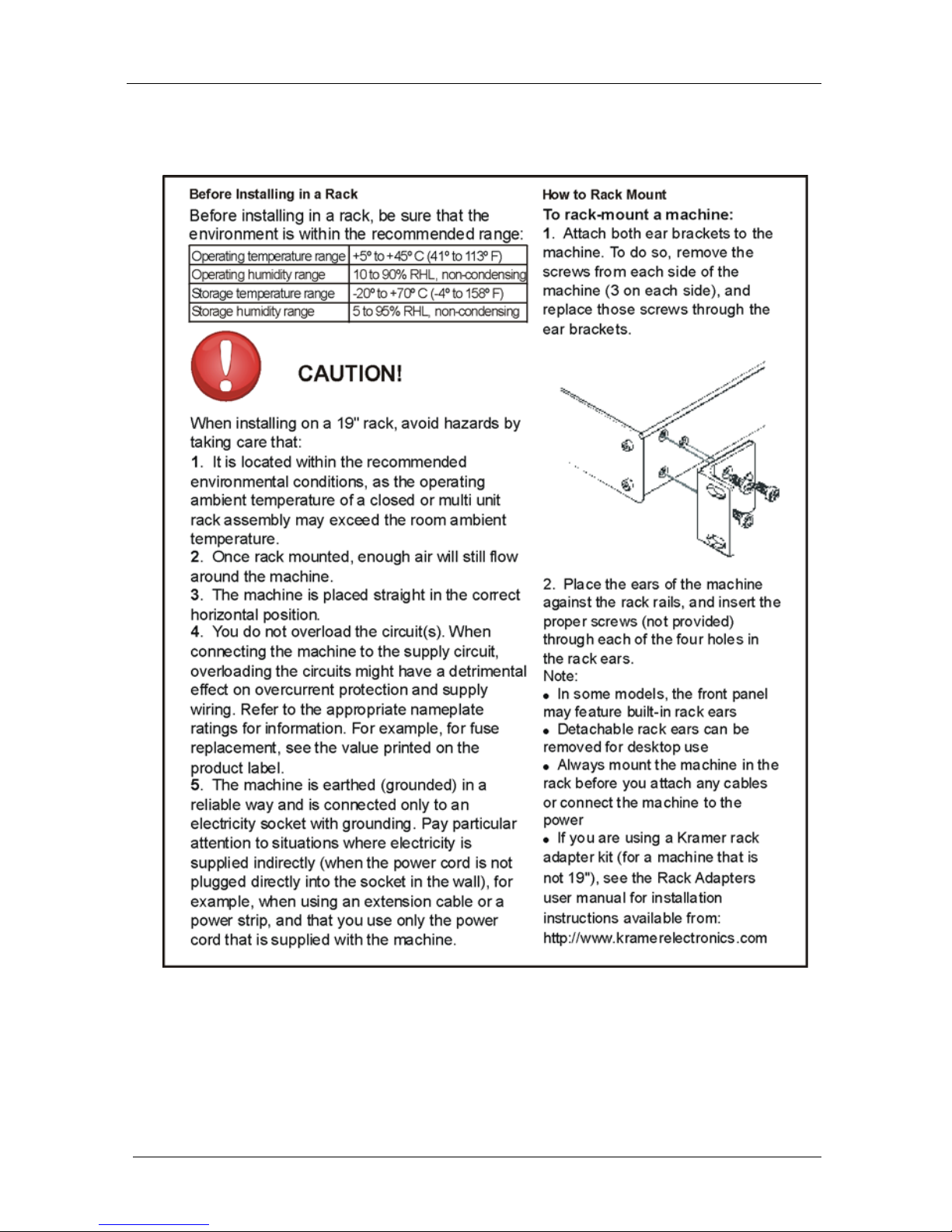
5 Installing the VS-88SDI in a Rack
.
This sect ion provi des instructio ns for rack mounting the 1U unit.
Page 13

Connecting the VS-88SDI
9
9
6 Connecting the VS-88SDI
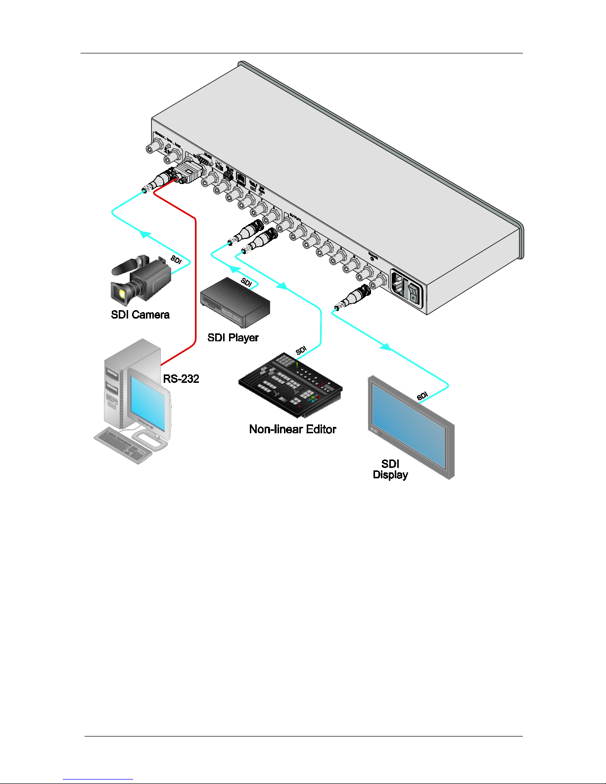
The VS-88SDI can switch one of the eight SDI inputs to any or all of the
eight SDI outputs, as t he example in
Figure 2 shows.
To connect the VS-88SDI , do the following
1
1. Connect up to eight SDI sources to the SDI INPUT BNC connectors (for
example , an SDI cam er a t o INPUT 1 and an SDI player to INPUT 8).
:
2. Connect the SDI OUTPUT BNC connectors to up to eight SDI acceptors
(for example, OUTPUT 1 to a non-linear editor, and OUTPUT 8 to an SDI
display).
3. Set the DIP-swit ches (s ee s ec tion
6.1.2).
4. Optionally
2
• A genlock source to the GENLOCK BNC connector
, connect:
• The LOOP BNC connector to the GENLOCK connector of the
next unit in the line, and rel ease the TERM but to n fo r looping
3
5. Connect a PC and/or controller (if requi red), to the:
• RS-232 port (see section
6.1), and/or
• RS-485 port (see section
6.2), and/or
• ETHERNET connector (see section
6.3)
6. Connect the power cord
4
1 Switch OFF the power on each de vice before connectin g it to your VS-88SDI. After connecting your VS-88SDI, switch on
its power and then switch on the power on each device
.
2 Not illustrated in Figure 2
3 Pushed in terminates the input. Release when the input extends to another unit
4 We recommend that you use only the power cord that is supplied with this machine
Page 14
KRAMER: SIMPLE CREATIVE TECHNOLOGY
Connecting the VS-88SDI
10
Figure 2: Connecting the VS-88SDI
6.1 Connecting the RS-232 Port
You can connect to the VS-88SDI via an RS-232 connection using, for
example, a PC. Note that a null-modem adapter/connection is not required.
To connect to the VS-88SDI via RS-232:
• Connect the RS-232 9-pin D-sub rear panel port on the VS-88SDI
unit via a 9-wire straight cable (pin 2 to pin 2, pin 3 to pin 3, pin 5
to pin 5) to the RS-232 9-pin D-sub port on your PC
Page 15

Connecting the VS-88SDI
11
11
6.1.1 Determining the Machine Number
Each unit must be identified by a unique Machine #. Determine the
Machine #
according to Table 3.
• When using a single unit, set the unit to Machine # 1.
• A master uni t mus t be Machine #1.
When connecting more than one VS-88SDI unit, set a different Machine #
on each uni t. The units do not have to be numbered sequentially but each
unit must have a unique machine number.
Table 3: Machine # DIP-Switch S ettings
Machine #
DIP-SWITCH
1 2 3 4
1 (Single or
master unit
1
OFF
ON )
OFF
OFF
OFF
OFF
OFF
OFF
2 OFF ON OFF OFF
3 ON ON OFF OFF
4 OFF OFF ON OFF
5 ON OFF ON OFF
6 OFF ON ON OFF
7 ON ON ON OFF
8 OFF OFF OFF ON
9 ON OFF OFF ON
10 OFF ON OFF ON
11 ON ON OFF ON
12 OFF OFF ON ON
13 ON OFF ON ON
14 OFF ON ON ON
15 ON ON ON ON
Note: After changing t he addre s s , the device must be reset by turning OFF
and ON.
6.1.2 Setti n g th e DIP-Switches
When controlling a unit via the RS-232 or RS-485 ports set the
DIP-switche s on the rear of the unit.
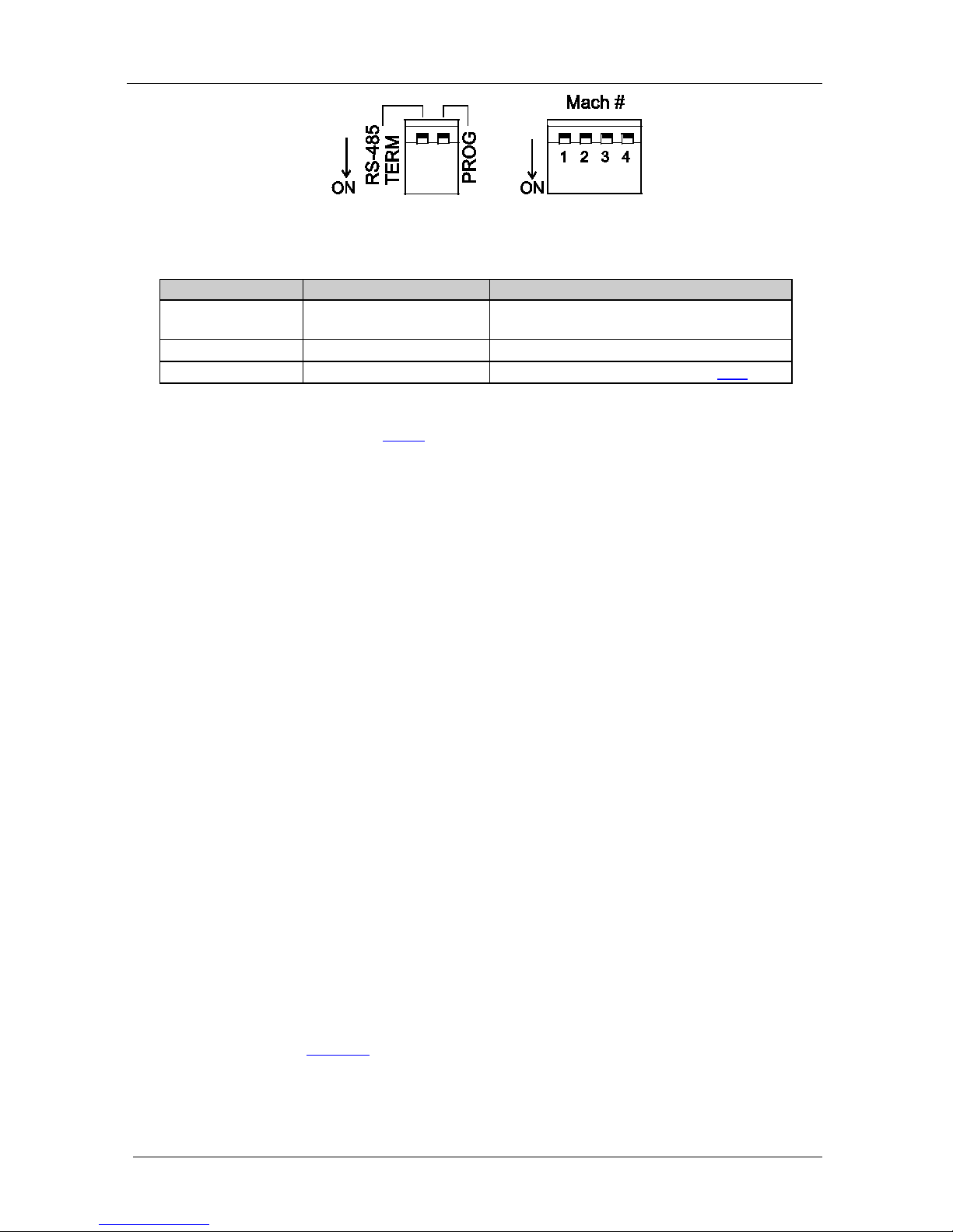
Figure 3 and Table 4 define the
DIP-switches
2
1 A single or master unit can have the address 0 or 1
:
2 The default address is 0 (all DIP-switches are OFF)
Page 16
KRAMER: SIMPLE CREATIVE TECHNOLOGY
Connecting the VS-88SDI
12
Figure 3: DIP-Switch Settings
Table 4: DIP-Switch Settings
DIPS
Function
Description
RS-485 Term RS-485 line termination OFF for no RS-485 line termination
ON for RS-485 120Ω line terminat i on
PROG Firmware updat e Set ON only to update device firmware
MACH # 1, 2, 3, 4 Self Address Sets the MACHINE # (see section 6.1.1)
The RS-485 TERM DIP-switch is used only when the R S-485 port is
connected (see section
6.2.2). The first and last units on the RS-485 line
(for example, the controller and the last VS-88SDI) must be terminated;
the units in between must not be terminated.
Set the PROG DIP-switch ON only while upda ting the unit firmware,
otherwise the switch must be O FF.
6.2 Connecting a PC or Controller to the RS-485 Port
You can operate the VS-88SDI via the RS-485 port from a distance of up to
1200 meters (3900ft) using any device equipped with an RS-485 port (for
example, a PC). For successful communication, you must set the RS-485
machine number and bus termination.
To connect a device with a RS-485 port to the VS-88SDI:
• Connect t he A (+) p i n on the RS-485 port of the PC to the A (+) pin on
the RS-485 port on the rear panel of the VS-88SDI
• Connect the B (–) pin on the RS-485 port of the PC to the B (–) pin on
the RS-485 port on the rear panel of the VS-88SDI
• Connect t he G pin o n the RS-485 port of the PC to the G pin on the
RS-485 port on the rear panel of the VS-88SDI
6.2.1 Setti n g th e Address Switches
To set the address DIP-switches:
• Assign Master Machine #1 to the master unit with the address
0 or 1 set in the DIP-switches
• Assign a unique Machine # from 2 to 15 for each VS-88SDI slave
unit using
Table 3. The units do not have to b e sequent i ally
numbered but they must have unique address es
Page 17
Connecting the VS-88SDI
13
13
6.2.2 Setting the Line Termination
To ensure correct operation, the RS-485 line must be terminated at both
ends. The master unit may be located at any part of the line, but when it is at
the end of the line, the termi nation switch must be set ON.
To set line termination, as shown in
Figure 3
:
• For the VS-88SDI units located at the ends of the RS-485 line, set
the RS-485 TERM DIP-switch ON
• For all other VS-88SDI units in the middle of the line, set the
RS-485 TERM DIP-switch OFF
6.3 Factory Reset
To perform a factory reset and reset the machine to its default values, press
the ETH RESET button in with a small screwdriver or pointed object.
6.4 Switching Genlocked Video Signals
The genlock feat ure lets you switch genlocked video s ignals according to
timing of the GENLOCK reference input
1
1. Connect the GENLOCK cable.
.
2. To set the genlock timing, press and hold for 3 sec onds the appropriate input
button as follows
2
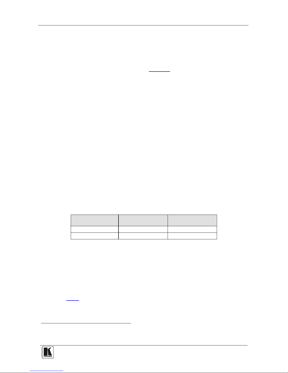
Table 5: Genlock Settings
:
To Set Press and Hold
for 3 Seconds
Displayed
PAL @50Hz IN 4 PAL 50H
NTSC @60Hz IN 5 NTSC 60H
Note: When turning the machine ON, the last stored setup i s s hown in the
7-segment display.
6.5 Connecting the Ethernet Port
You can connect the VS-88SDI via the ETHERNET in the following ways:
• For direct connection to the PC, use a crossover cable (see section
6.5.1)
• For connection vi a a network hub or ne twork ro uter, use a
1 According to SMPTE RP-168. The sources must be genlocked to the GENLOCK input in order to switch cleanly
2 The unit will detect automatically when SD-SDI inputs are used
Page 18
KRAMER: SIMPLE CREATIVE TECHNOLOGY
Connecting the VS-88SDI
14
straight-through cable (see section 6.5.2)
6.5.1 Connecting the ETHERNET Port Directly to a PC (Crossover
Cable)
You can connect the Ethernet port of the VS-88SDI to the Ethernet port on
your PC, via a crossover cable with RJ-45 connectors.
This type of connection is recommended for identification of the factory default
IP address
1
After connecting the Ethernet port, c onfigure yo ur PC as follows:
of the VS-88SDI during the init ial config urat i on
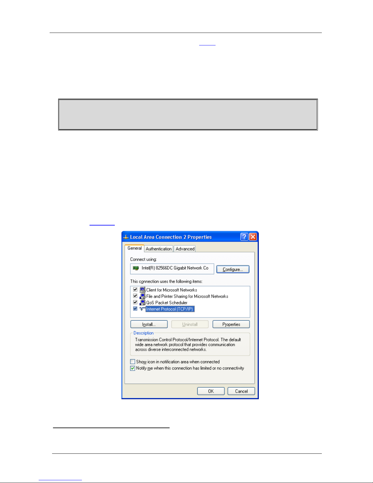
1. Right-click the My Network Places icon on your desktop.
2. Select Properties.
3. Right-click Local Area Connection Properties.
4. Select Properties.
The Local Area Connection Properties window appears.
5. Select the Int ernet Prot oco l ( TCP/ IP) an d c lick th e Properties Button (see
Figure 4).
Figure 4: Local Area Connection Properties Window
1 The default IP address is 192.168.1.39
Page 19
Connecting the VS-88SDI
15
15
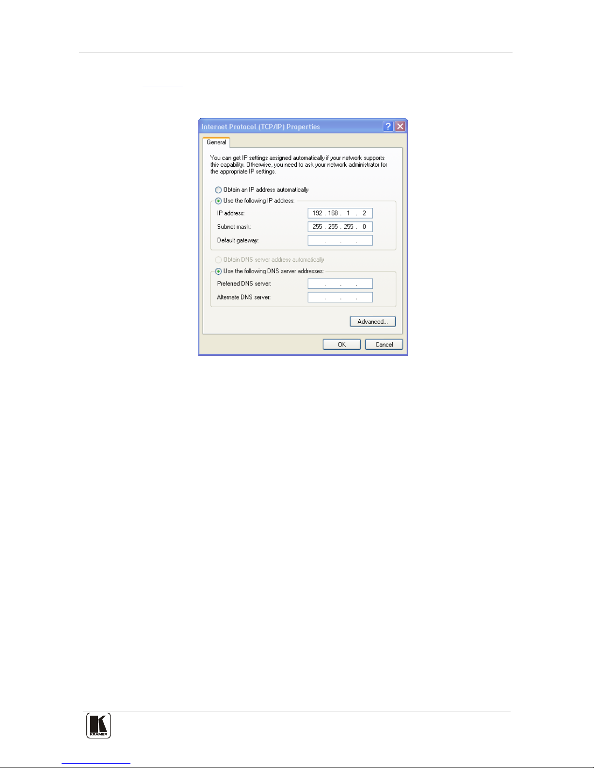
6. Select Use the following IP Address , an d f ill in th e deta ils as sh own in
Figure 5.
7. Click OK.
Figure 5: Internet Protocol (TCP/IP) Properties Window
6.5.2 Connecting the ETHERNET Port via a Network Hub (StraightThrough Cable)
You can connect the Ethernet port of the VS-88SDI to the Ethernet por t on
a network hub or ne twork router, via a straig ht-through cable with RJ-45
connectors.
6.6 Configuring the Ethernet Port
To configure the Ethernet port, download t he Device Properties Ethernet
configuration software. Extract the file to a folder and create a shortcut on
your desktop to the file.
Follow these steps to configure the port:
1. Double click the deskt op i con.
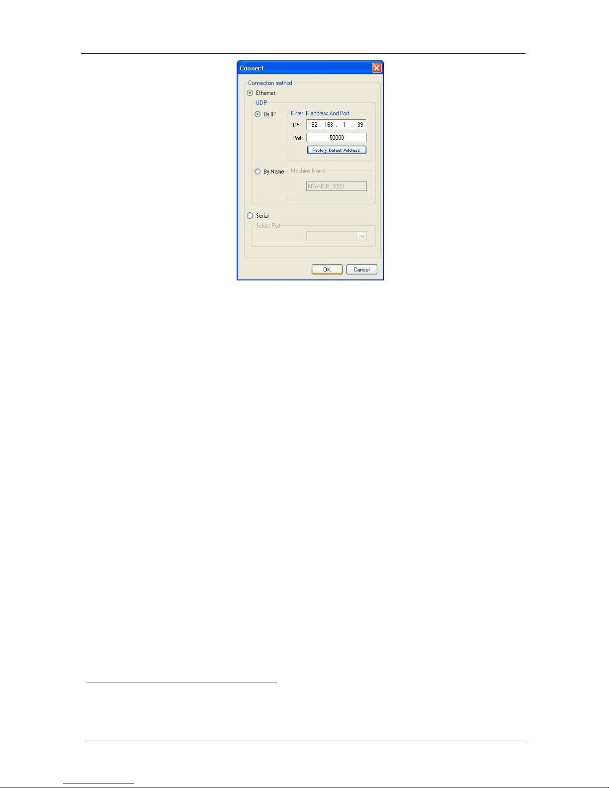
The Conn ect s creen a ppea rs as fol lows:
Page 20
KRAMER: SIMPLE CREATIVE TECHNOLOGY
Connecting the VS-88SDI
16
Figure 6: Connect Screen
2. Select the method to connect to the Ethernet port of the VS-88SDI.
Select:
Ethernet, if you know the IP address number
1
or the mac hine
name. The default name for the machine is KRAMER_XXXX
2
Serial, if you are connected via a serial port
3. Click OK.
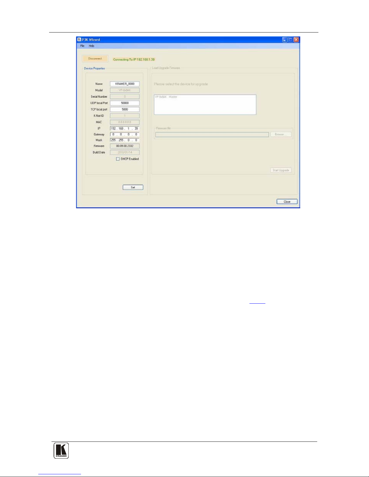
The Device Properties window appears:
1 The default IP address is 192.168.1.39
2 The four digits are the last four digits of the machine’s serial number.
Page 21
Connecting the VS-88SDI
17
17
Figure 7: Device Properties Screen
4. If required, make changes and press Set. If not, click Close.
6.7 Controlling via the Ethernet Port
You can control t he VS-88SDI via RS-232/RS-485 or the Ethernet using
the Kramer K-Router application.
If yo u are controlli ng a sta ndalone unit via RS-232 or the Ethernet,
configure the unit as master (Mach No. 1), see section
6.1.1.
6.8 Usi n g th e Ethernet Reset Button
To reset Ethernet parameters to the factory defaults:
1. Turn the power switch OFF and then ON while pressing the ETH RESET
button.
2. The unit powers up and loads its memory with the factory default
definitions.
3. The unit also erases all stored presets, returns to the default Protocol 3000
and in dica tes “F-rst” on the 7-segm ent dis play .
Page 22

KRAMER: SIMPLE CREATIVE TECHNOLOGY
Operating the VS-88SDI
18
7 Operating the VS-88SDI
You can operate your VS-88SDI using:
• The fro nt panel butto ns
• RS-232/RS-485 serial commands transmitted by a touch screen
system, PC, or other serial controller
• The RC-IR3 infrared remote control transmitter
7.1 Operating the VS-88SDI from the Front Panel
The following operations are performed by using the front panel buttons.
7.1.1 Power On Display
When the VS-88SDI is powered on, the display briefly shows the 4-digit
firmware version number, the genlock timing setting, and the n the display
changes to its normal operating display.
7.1.2 Using the AT ONCE and CONFIRM Modes
Choose to work in either the AT ONCE or the CO NFIRM modes. When the
VS-88SDI operates in the AT ONCE mode, pressing an OUT-IN
combination implements t he switch immediately. In the CONFIRM mode,
the change does not take place until the TAKE button is pressed.
The AT ONCE mode is faster si nc e execution is immed ia te and actions
require no user confirmation. However, no protection is offered against
changing an action in error.
In the CONFIRM mode:
• You can key-in several acti ons and then confirm them by pressi ng
the “TAKE” button, to si mult a neo usly activate the multiple
switches
• Every action requires user confirmation, protecting against
erroneous switching due to human error (pressing the wrong
button)
• Execution is delayed until the user confirms the action
7.1.3 Switching in the AT ONCE Mode
To switch an input to an output in the AT ONCE mode, do the following:
1. Press an OUT SELE CT but ton
1
1 From 1 to 8
or the ALL button.
The 7-s egmen t d is play fl ash es.
Page 23

Operating the VS-88SDI
19
19
2. Press an IN SELEC T butt on1 or the OFF button
1
7.1.4 Toggling Between Modes
.
The selected input switches t o the selected output . The digits displayed in
the 7-segment display change as appropriate.
To toggle between the AT ONCE and CONFIRM modes, do the following:
1. Press the TAKE button to toggle from the AT ONCE mode (in which the
TAKE button is not lit) to the CONFIRM mode (in which the TAKE button
illuminates).
Actions now require user confirmation and the TAKE button il lum inates .
2. Press the illuminated TAKE button to toggle from the CONFIRM mode
back to the AT ONCE mode.
TAKE button turns off and actions no longer require user confirmation.
7.1.5 Switching in the CONFIRM Mode
To switc h in the CONFIRM mode, when t he TAKE button is illuminated ,
do the following:
1. Press an OUT-IN combination.
The 7-segment display flashes
2
2. Press the TAKE button to confirm the action.
The 7-segment display stops flashing. The TAKE button stays lit.
.
To confirm several actions (in CONFIRM mode), do the following:
1. Press each OUT-IN combination in sequence.
The 7-segment display flashes.
2. Press the TAKE button to confirm all the actions.
The 7-segment display stops flashing. The TAKE button stays lit.
7.1.6 Storing an Input/Output Configuration
You can store up to 16 configurations in memo ry and recall them as preset s
using the e ight IN S ELECT buttons and the eight OUT SEL ECT butt ons.
To store the current confi guration, do the fo llowing:
1. Press the STO button.
The STO button flashes.
2. Press one of the IN / OUT SELECT buttons.
The curren t configuration is stored in m emory a t t he chos en preset #.
1 For immediate switching
2 The timeout lasts for 10 seconds
Page 24

KRAMER: SIMPLE CREATIVE TECHNOLOGY
Operating the VS-88SDI
20
7.1.7 Recalling an Input/Output Configuration
To recall an input/output configura tion, d o the following:
1. Press the RCL button.
The RCL button flashes.
2. Press the appropriate IN / OUT SELECT button (the button #
corresponding to the preset #).
The ch osen pres et c onfig ur ation is res tor ed f rom m emory.
Note: Recalling an invalid setu p gives an error in dication (se e s ecti on
7.1.10).
If you cannot remember which of the eight input/outp ut configurations is
the one that you want, set the VS-88SDI to the CONFIRM mode and
manually s can all the input/output configurations until you locate it.
7.1.8 Locking the Front Panel
Lock the front panel butto ns to prevent unwanted key presses from
changing the existing set up.
• To lock the front panel, press and hold the LOCK ke y for three
seconds.
The LOCK key illuminates and the front panel keys are inactivated
• To unlock the fro nt panel, press and hold the illuminated LOCK
key until the light turns off.
The front panel keys are activated
7.1.9 Switching Protocols
You can operate the VS-88SDI using either the KRAMER 2000 or the
default KRAMER 3000 serial protocol.
• To choose the Kramer 2000 protocol instead of the default Protocol
3000, press LOCK and OUT 2 at the same time.
LOCK flashes briefly if the change was made correctly
• To revert to t he Kramer 3000 protocol, press LOCK and OUT 3 at
the same time.
LOCK flashes briefly if the change was made correctly
7.1.10 Indicating Errors
If the fro nt panel buttons were incorrectly pressed, such as pressing two
keys at once, or an invalid setup # was chosen for recall, the following error
indication occurs:
• The STO, RCL, LOCK, and TAKE buttons all flash together for
one second and return to their previous state
If an error is indicated, retry the previous action or choose a new action.
Page 25

Technical Specifications
21
21
7.2 Using Serial Commands
To operate the VS-88SDI using serial commands, Kramer offers control
software that can do this. You can download free software from the Kramer
Electronics Web site.
• For an explanation of all KRAMER 3000 commands, see section
11.3
• For an explanation of all KRAMER 2000 commands, see section
12
7.3 Usi n g th e Infrared Remote Controller
To operate the VS-88SDI using the RC-IR3 infrared remote controller, see
the User Manual packed with the remote controller.
Note:
• The remote control cannot set single or dual mode operation or
change genlock timing. They can only be set from the front pa nel
• The IR remote can only set 8 preset configurations equivalent to
OUT1 to OUT8
8 Technical Specifications
The VS-88SDI technical specifications are shown in Table 6:
Table 6: VS-88SDI Technical Specifications
1
INPUTS:
8 SMPTE-259M, 344M serial video, 75Ω on BNC connectors
OUTPUTS: 8 equalized and reclocked SMPTE-259M, 344M outputs 75Ω on BNC connectors
MAX. OUTPUT LEVEL: 800mVpp /75Ω
DATA RATE: 540Mbps
EQUALIZATION:
Automatic equalization for losses on 75Ω coaxial cable
CONTROLS: Front-panel, RS-232, RS-485, ETHERNET, remote infrared
POWER SOURCE: Universal, 100-240V AC, 50/60Hz 24VA
DIMENSIONS: 19" x 7" x 1U W, D, H, rack mountable
WEIGHT: 2.6kg (5.7lbs) approx
ACCESSORIES: Power cord, rack “ears” and IR remote control transmitter
OPTIONS: External remote IR receiver cable
1 Specifications are subject to change without notice
Page 26
KRAMER: SIMPLE CREATIVE TECHNOLOGY
Communication Parameters
22
9 Communication Parameters
The following table lists the communication parameters for Protocol 2000
and Protocol 3000.
Table 7: Communication Parameters
RS-232
Protocol 2000 Protocol 3000 (Default)
Baud Rate: 9600 Baud Rate: 115,200
Data Bits: 8 Data Bits: 8
Stop Bits: 1 Stop Bits: 1
Parity: None Parity: None
Command Format: HEX Command Format: ASCII
Example (Output 1 to Input
1):
0x01, 0x81, 0x81, 0x81 Example (Output 1 to Input
1):
#AV 1>1<CR>
Switching Protocol
P2000 -> P3000 P3000 -> P2000
Command: 0x38, 0x80, 0x83, 0x81 Command: #P2000<CR>
Front Panel: Press and hold Output 1 and
Output 2 simultaneously
Front Panel: Press and hold Output 1 and Output 3
simultaneously
Ethernet
Default Settings Reset Settings
IP Address: 192.168.1.39 Power cycle the unit while holding in the Factory Reset
button, located on the rear panel of the unit.
TCP Port #: 5000
UDP Port #: 50000
10 Using the P3K Wizard
P3K is a Kramer software program for accessing and changing device
parameters and upgrading the machine firmware. The P3K program can be
downloaded from the Kramer Web site at www.kramerelectronics.com.
10.1 Changing the Device Parameters
To change the device parameters do the following:
1. Connect a PC to the VS-88SDI using any one of the following connections:
• Connect a serial cable from an RS-232 9-pin D-sub rear panel
port on the PC to the VS-88SDI as explained in section 6.1.
• Connect an RJ-45 Ethernet cable from the Ethernet port on the
PC to the Ethernet port on the VS-88SDI.
Page 27
Using the P3K Wizard
23
23
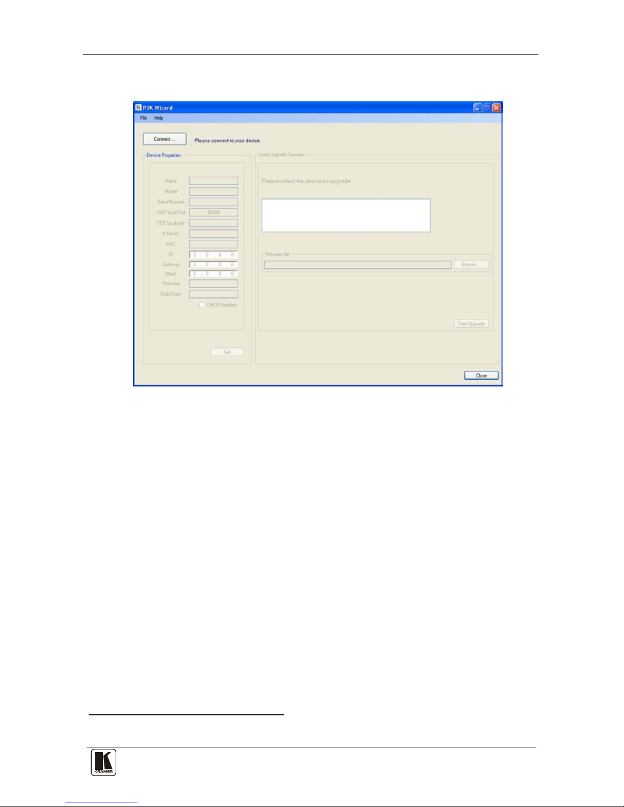
2. Open the P3K Wizard by double-clicking the desktop icon P3K Wizard.
The P3K Wizard screen appears
1
:
Figure 8: P3K Wizard Screen
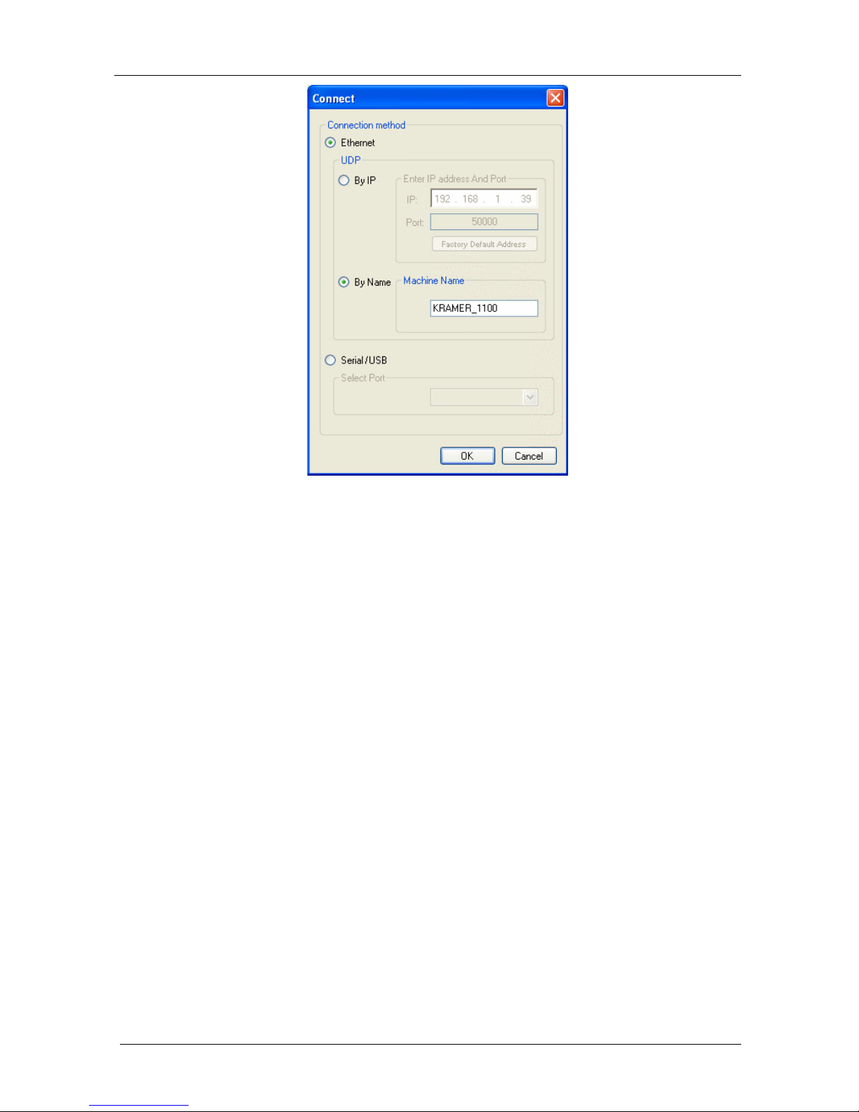
3. Click the Connect button to open the Connect window.
1 The screens appearing in this manual are examples of the process. The actual screens may differ in their content.
Page 28
KRAMER: SIMPLE CREATIVE TECHNOLOGY
Using the P3K Wizard
24
Figure 9: Connect Window
4. Choose the appropriate type of connection: Ethernet BY IP, BY NAME, or
SERIAL/US B, an d click OK.
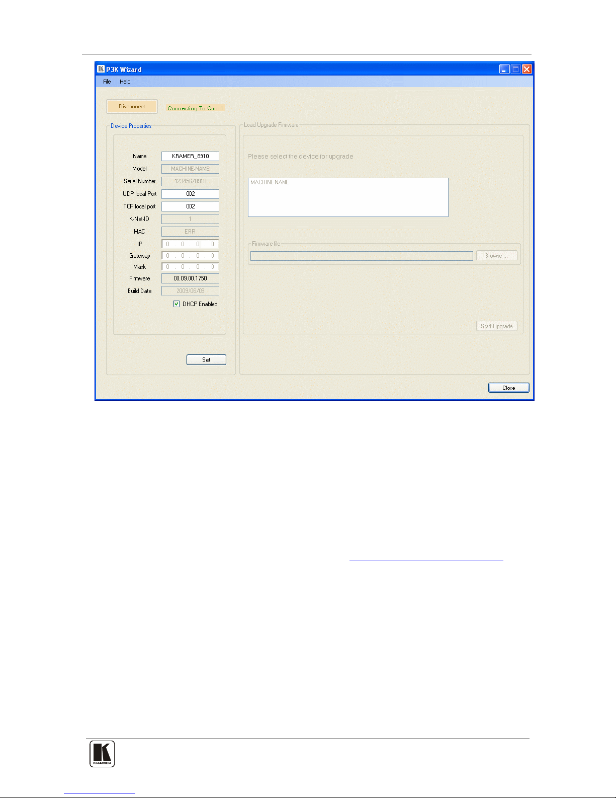
The Connect window disappears and the Device Properties window
appears.
Page 29
Using the P3K Wizard
25
25
Figure 10: Device Properties Window
5. Change the parameters in the white fields as requ ire d an d click SET.
10.2 Updating the VS-88SDI Firmware
The VS-88SDI uses a microcontroller that runs firmware located in FLASH
memory.
The latest version of firmware and installation instructions can be
downloaded from the Kramer Web site at www.kramerelectronics.com
.
Page 30

KRAMER: SIMPLE CREATIVE TECHNOLOGY
Kramer Protoc ol 3000
26
11 Kramer Protocol 3000
The VS-88SDI can be operated using serial commands from a PC, remote
controller, or touch screen. The unit communicates using the default Kramer
Protocol 3000 but can also use Kramer Protocol 2000.
This section describes:
• How to switch between Protocol 3000 and Protocol 200 0 (see
section
11.1
)
• Kramer Protocol 3000 syntax (see section
11.2)
• Kramer Protocol 3000 commands (see section
11.3)
11.1 Switching Protocols
Protocols can be switched either from the front panel buttons or by
transmitting protocol commands.
To switch protocols using the front panel buttons:
• To choose Protocol 2000, press LOCK and OUT 2 at the same time
• To choose the Protocol 3000, press LOCK and OUT 3 at the same
time
To switch protocols using protocol commands:
• To switc h from Protocol 3000 to Protocol 2000, send the following
command:
#P2000<CR>
• To switc h from Protocol 2000 to Protocol 3000, send the following
command:
0x38, 0x80, 0x83, 0x81
Note: If you ar e using Kr amer’s Windows
®
-based control software
1
it
operates only with Protocol 2000. If the VS-88SDI is set to Protocol 3000,
it automatically switche s to Protocol 2000.
1 Download the latest software from our Web site at http://www.kramerelectronics.com
Page 31
Kramer Protoc ol 3000
27
27
11.2 Kramer Protocol 3000 Syntax
Protocol 3000 communicates at a data rate of 115200 baud, no parity, 8 data
bits and 1 stop bit.
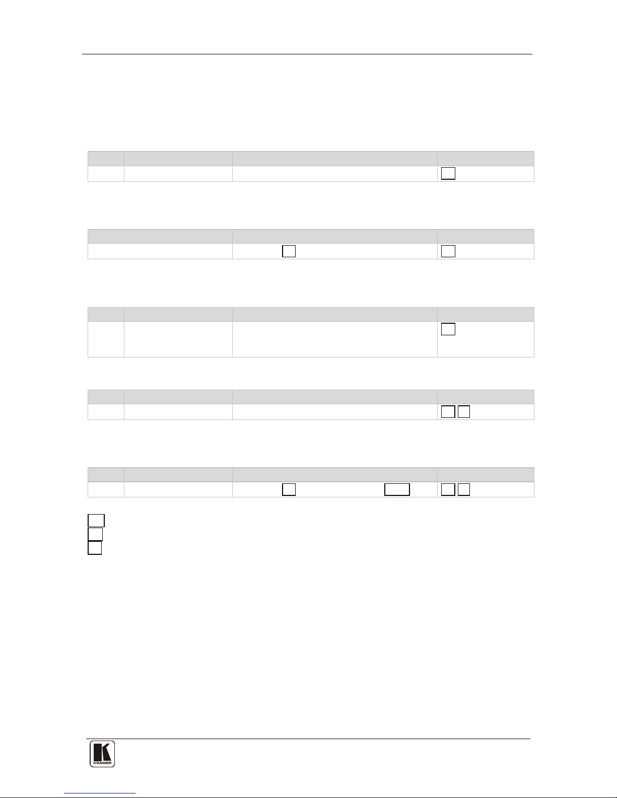
11.2.1 Host Message Format
Start Address (optional) Body Delimiter
#
Destination_id@
Message
CR
11.2.1.1 Simple Command
Command string with only one command without addressing:
Start Body Delimiter
#
Command SP Parameter_1,Parameter_2,… CR
11.2.1.2 Command String
Formal syntax with commands conca tenatio n and addressing:
Start Address Body Delimiter
#
Destination_id@
Command_1 Parameter1_1,Parameter1_2,…|
Command_2 Parameter2_1,Parameter2_2,…|
Command_3 Parameter3_1,Parameter3_2,…|…
CR
11.2.2 Device Message Format
Start Address (optional) Body delimiter
~
Sender_id@
Message
CR LF
11.2.2.1 Device Long Response
Echoing command:
Start Address (optional) Body Delimiter
~
Sender_id@
Command SP [Param 1 , Param2 … ] result CR LF
CR = Carriage return (ASCII 13 = 0x0D)
LF = Line feed (ASCII 10 = 0x0A)
SP = Space (ASCII 32 = 0x20)
Page 32

KRAMER: SIMPLE CREATIVE TECHNOLOGY
Kramer Protoc ol 3000
28
11.2.3 Command Terms
Command
A sequence of ASCII letters ('A'-'Z', 'a'-'z' an d '-').
Command and parameters must be separated by at least one space.
Parameters
A sequence of alphameric ASCII characters ('0'-'9','A'-'Z','a'-'z' an d som e
special characters for specific commands). Parameters are separated by
commas.
Messag e string
Every command entered as part of a message string begins with a message
starting character and ends with a message closing character.
Note: A string can contain more than one command. Commands are
separated by a pipe ( '|' ) character.
Message starting character
'#' – For host command/query
'~' – For machine response
Device address (Optional, for K-NET)
K-NET Device ID followed b y '@'
Query sign
'?' follows some command s to define a query request.
Message closing character
CR – For host messages; carriage return (ASCII 13)
CRLF – For machine messages; carriage return (ASCII 13) + line-feed
(ASCII 10)
Command chain separator character
When a mess age string contains more then one command, a pipe ( '|' )
character separates each command.
Spaces between parameters or command terms are ignored.
11.2.4 Entering Commands
You can directly enter all commands using a terminal with ASCII
communications software, such as HyperTerminal, Hercules, etc. Connect
the terminal to the serial, Ethernet, o r USB port on the Kramer device. To
enter
CR , press the Enter key.
( LF i s also sent but is ignored by command parser).
For commands sent from some non-Kramer controllers like Crestron, some
characters require special coding (such as, /X##). Refer to the contro lle r
manual.
Page 33

Kramer Protoc ol 3000
29
29
11.2.5 Command Forms
Some commands have short name syntax in additio n to long name syntax to
allow faster typing. The response is always in long syntax.
11.2.6 Command Chaining
Multiple commands can be chained in the same str ing. Each command is
delimited by a pipe character ( '|' ). When chaining commands, enter the
message starting character and the message closing character only once,
at the beginning o f the stri ng and at the end.
Commands in the string do no t execute until the closing character is
entered.
A separate response is sent for ever y command in the chain.
11.2.7 Maximum String Length
64 characters
11.2.8 Backward Support
Protocol 2000 is transparently supported by Protocol 3000. You can switch
between protocols using a switch protocol command from either platform.
Page 34
KRAMER: SIMPLE CREATIVE TECHNOLOGY
Kramer Protoc ol 3000
30
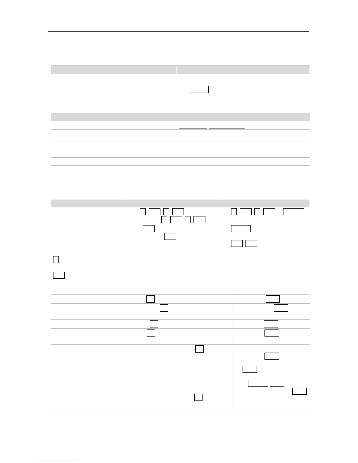
11.3 Kramer Protocol 300 0 Commands
11.3.1 Device Initiated Messages
Command Syntax
Switcher actions:
Video channel has sw itc hed ( brea kaway mode)
VID IN>OUT
11.3.2 Result and Error Codes
Syntax
Command ran suc cess fully , no erro r.
COMMAND PARAMETERS OK
Protocol Errors:
Syntax error ERR001
Command not ava ilab le for t his dev ice ERR002
Parameter is out of range ERR003
Unauthorized access (co mmand run withou t the
matching login).
ERR004
11.3.3 57BBasic Routing Commands
Command Syntax Response
Switch video
VID IN>OUT, IN>OUT, …
Short form: V IN>OUT, IN>OUT, …
VID IN>OUT, IN>OUT, …RESULT
Read video conne ction
VID? OUT
Short form: V? OUT
VID? *
VID IN>OUT
VID IN>1, IN>2, …
Parameter Description:
IN = Input nu mber o r '0' to d is connec t o utput.
'>' = Connection character between in and out parameters.
OUT = Output number or ' *' fo r a ll o utp uts.
Examples:
Switch video input 2 t o o utpu t 4
#V 2>4CR ~VID 2>4 OKCRLF
Switch video input 4 t o o utpu t 2
in machine number 6
#6@VID 4>2CR
~6@VID 4>2 OKCRLF
Disconnect video ou tput 4
#AV 0>4CR ~AV 0>4 OKCRLF
Switch video input 3 to all
outputs
#V 3>* CR
~VID 3>* OKCRLF
Chaining
multiple
commands
#V 1>* | V 3>4, 2> 2, 2> 1, 0>2 | V 3>9 | V? * CR
1. Switch video from input 1 to all outputs.
2. Switch video input 3 to output 4, video input 2 to
output 2, v ideo i nput 2 to ou tpu t 1 and d isconne ct vide o
output 2.
3. Switch video input 3 to output 9 (non-existent).
4. Get status of all video lin ks.
Command processin g be gins af ter en ter ing CR . A
response is sent for each command aft er processin g.
~VID 1>* OKCRLF
~VID 3>4, 2>2, 2 >1, 0>2
OKCRLF
~VID ERR003 CRLF
~VID 2>1, 0>2, 1 >3, 3>4 CRLF
Page 35
Kramer Protoc ol 3000
31
31
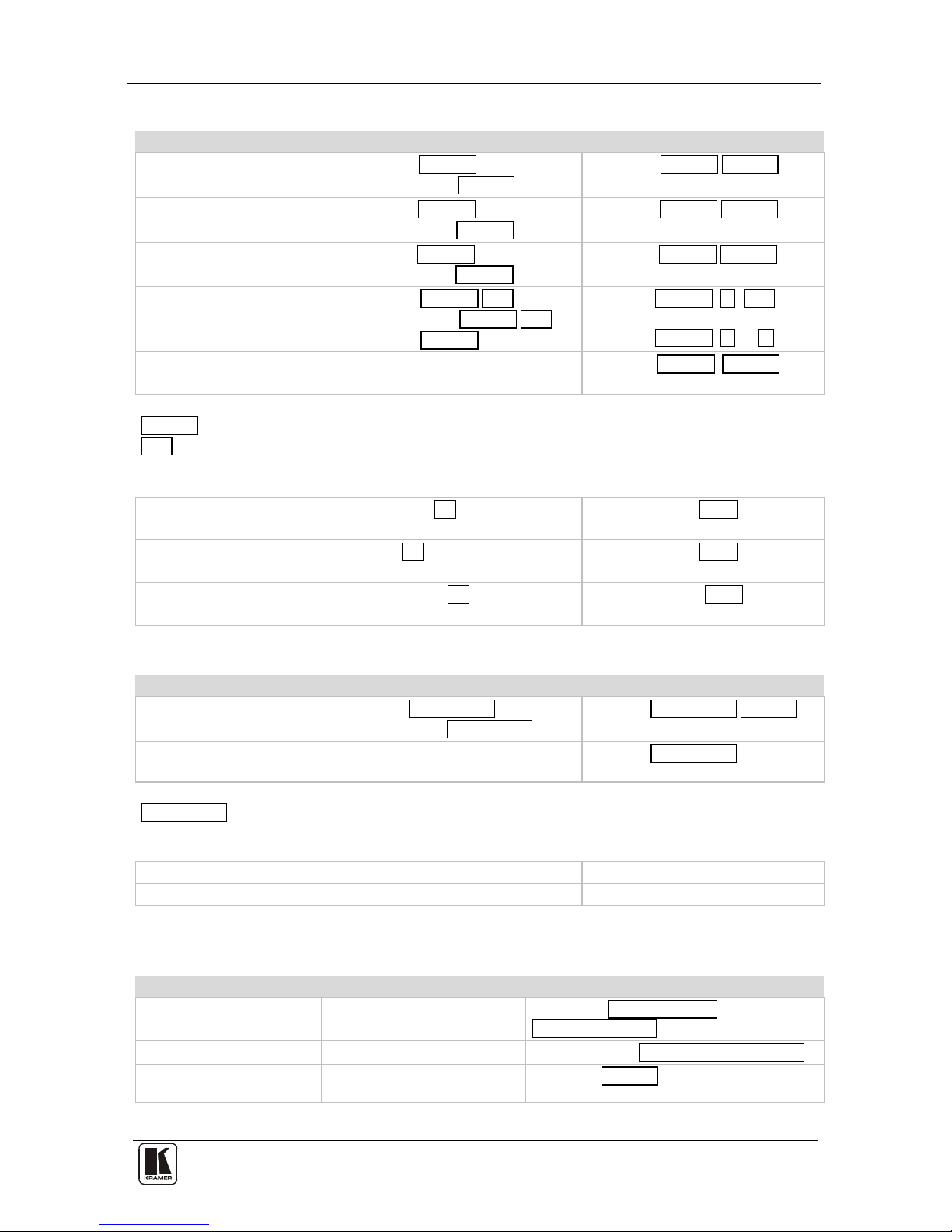
11.3.4 Preset Commands
Command Syntax Response
Store current connect ions to
preset
PRST-STO PRESET
Short form: PSTO PRESET
PRST-STO PRESET RESULT
Recall saved preset
PRST-RCL PRESET
Short form: PRCL PRESET
PRST-RCL PRESET RESULT
Delete saved pr eset
PRST-DEL PRESET
Short form: PDEL PRESET
PRST-DEL PRESET RESULT
Read video conne ction s from
saved preset
PRST-VID? PRESET,OUT
Short form: PVID? PRESET,OUT
PRST-VID? PRESET, *
PRST-VID PRESET, IN>OUT
PRST-VID PRESET, IN>1, IN>2,…
Read saved presets list PRST-LST?
Short form: PLST?
PRST-LST PRESET, PRESET, …
Parameter Description:
PRESET = Preset number.
OUT = Output in p rese t to di splay , ' *' f or all.
Examples:
Store current video connec tions
to preset 5
#PRST-STO 5CR ~PRST-STR 5 OKCRLF
Recall video connections from
preset 3
#PRCL 3CR ~PRST-RCL 3 OKCRLF
Show source of vide o ou tput 2
from preset 3
#PRST-VID? 3,2CR ~PRST-VID 3: 4>2 CRLF
11.3.5 Operation Commands
Command Syntax Response
Lock front pa nel
LOCK-FP LOCK-MODE
Short form: LCK LOCK-MODE
LOCK-FP LOCK-MODE RESULT
Get front panel locking sta te LOCK-FP?
LOCK-FP LOCK-MODE
Parameter Description:
LOCK-MODE = Front panel locking st ate:
‘0’ or ‘off’ to u nl oc k fron t pa ne l butt ons
‘1’ or ‘on’ to loc k front pa nel bu ttons
Reset device RESET RESET OK
Switch to protocol 2000* P2000 P2000 OK
* Protocol 2 000 has a co mmand to swi tch ba c k to A SCII pro toc ol ( like Proto co l 3000)
11.3.6 Machine Information Commands
Command Syntax Response
Read in/out count INFO-IO?
INFO-IO: IN INPUTS_COUNT, OUT
OUTPUTS_COUNT
Read max preset count INFO-PRST?
INFO-PRST: VID PRESET_VIDEO_COUNT
Reset to factory default
configuration
FACTORY
FACTORY RESULT
Page 36
KRAMER: SIMPLE CREATIVE TECHNOLOGY
Kramer Protoc ol 3000
32
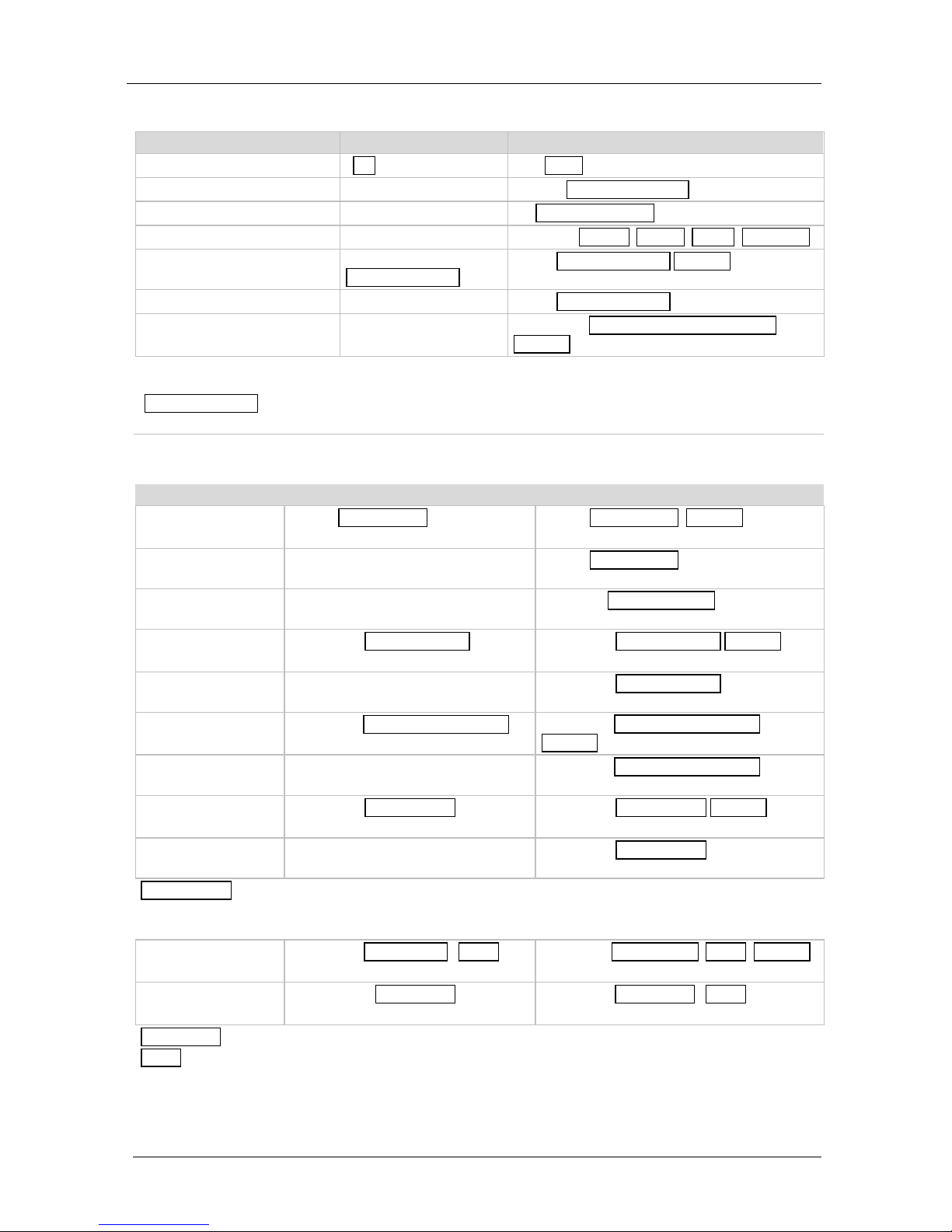
11.3.7 Identification Commands
Command Syntax Response
Protocol handsh aking
#CR ~OK CRLF
Read device model MODEL?
MODEL MACHINE_MODEL
Read device ser ial nu mber SN?
SN SERIAL_NUMBER
Read device f irmware ve rsion VERSION?
VERSION MAJOR .MINOR .BUILD .REVISION
Set machine name NAME
MACHINE_NAME
NAME MACHINE_NAME RESULT
Read machine name NAME?
NAME MACHINE_NAME
Reset machine name to factory
default*
NAME-RST
NAME-RST MACHINE_FACTORY_NAME
RESULT
*Note: The machine name is not the same as the model na me. The machine name is used to iden tify a specif ic
machine or a n etwor k in use (wi th DNS fea ture on ).
MACHINE_NAME = Up to 14 alphameric chars.
* Machin e f actory name = Model name + last 4 digits from serial number.
11.3.8 Network Setting Commands
Command Syntax Response
Set IP addres s
NET-IP IP_ADDRESS
Short form: NTIP
NET-IP IP_ADDRESS RESULT
Read IP address NET-IP?
Short form: NTIP?
NET-IP IP_ADDRESS
Read MAC address NET-MAC?
Short form: NTMC?
NET-MAC MAC_ADDRESS
Set subnet mask
NET-MASK SUBNET_MASK
Short form: NTMSK
NET-MASK SUBNET_MASK RESULT
Read subnet mask NET-MASK?
Short form: NTMSK?
NET-MASK SUBNET_MASK
Set gateway add ress
NET-GATE GATEWAY_ADDRESS
Short form: NTGT
NET-GATE GATEWAY_ADDRESS
RESULT
Read subnet mask NET-GATE?
Short form: NTGT?
NET-GATE GATEWAY_ADDRESS
Set DHCP mode
NET-DHCP DHCP_MODE
Short form: NTDH
NET-DHCP DHCP_MODE RESULT
Read subnet mask NET-DHCP?
Short form: NTDH?
NET-DHCP DHCP_MODE
DHCP_MODE =
‘0’ – Don't u se DHCP (Use IP set by fact ory or I P s et co mmand) .
‘1’ – Try to u se D HCP, if una vailabl e u se IP a s abo ve.
Change protocol
Ethernet port
ETH-PORT PROTOCOL , PORT
Short form: ETHP
ETH-PORT PROTOCOL ,PORT RESULT
Read protocol
Ethernet port
ETH-PORT? PROTOCOL
Short form: ETHP?
ETH-PORT PROTOCOL , PORT
PROTOCOL = TCP/UDP (transport layer protocol)
PORT = Ethernet port that accep ts Prot ocol 30 00 commands
1-6553 5 = User defined port
0 - Reset port to fa ctory def au lt (500 00 for UDP, 5 000 for TCP)
Page 37

Hex Table (Prot ocol 2000)
33
33
12 Hex Table (Protocol 2000)
Table 8 lists the Hex values for a single machine (M ACHINE # 1):
Table 8: VS-88SDI Hex Codes for Switching via RS-232/RS-485
OUT 8
OUT 7
OUT 6
OUT 5
OUT 4
OUT 3
OUT 2
OUT 1
01
81
88
81
01
81
87
81
01
81
86
81
01
81
85
81
01
81
84
81
01
81
83
81
01
81
82
81
01
81
81
81
IN 1
01
82
88
81
01
82
87
81
01
82
86
81
01
82
85
81
01
82
84
81
01
82
83
81
01
82
82
81
01
82
81
81
IN 2
01
83
88
81
01
83
87
81
01
83
86
81
01
83
85
81
01
83
84
81
01
83
83
81
01
83
82
81
01
83
81
81
IN 3
01
84
88
81
01
84
87
81
01
84
86
81
01
84
85
81
01
84
84
81
01
84
83
81
01
84
82
81
01
84
81
81
IN 4
01
85
88
81
01
85
87
81
01
85
86
81
01
85
85
81
01
85
84
81
01
85
83
81
01
85
82
81
01
85
81
81
IN 5
01
86
88
81
01
86
87
81
01
86
86
81
01
86
85
81
01
86
84
81
01
86
83
81
01
86
82
81
01
86
81
81
IN 6
01
87
88
81
01
87
87
81
01
87
86
81
01
87
85
81
01
87
84
81
01
87
83
81
01
87
82
81
01
87
81
81
IN 7
01
88
88
81
01
88
87
81
01
88
86
81
01
88
85
81
01
88
84
81
01
88
83
81
01
88
82
81
01
88
81
81
IN 8
Page 38

KRAMER: SIMPLE CREATIVE TECHNOLOGY
Kramer Protoc ol 2000
34
13 Kramer Protocol 2000
The VS-88SDI is compatible with Kramer’s Protocol 2000
1
Table 9: Protocol Definitions
, version 0.50.
This RS-232/RS-485 communication protocol uses four bytes of
information as defined below. The default data rate is 9600 baud, with no
parity, 8 data bits, and 1 stop bit.
MSB
LSB
DESTI-
NATION
INSTRUCTION
0 D N5
N4
N3
N2
N1
N0
7 6 5 4 3 2 1
0
1st byte
INPUT
1
I6
I5
I4
I3
I2
I1
I0
7 6 5 4 3 2 1
0
2nd byte
OUTPUT
1
O6
O5
O4
O3
O2
O1
O0
7 6 5 4 3 2 1
0
3rd byte
MACHINE NUMBER
1
OVR X M4
M3
M2
M1
M0
7 6 5 4 3 2 1
0
4th byte
1
st
BYTE: Bit 7 – Defined as 0.
D – “DESTINATION”: 0 - for sending information to the switchers (from the PC);
1 - for sending to the PC (from the switcher).
N5…N0 – “INSTRUCTION”
The function that is to be performed by the switcher(s) is defined by the INSTRUCTION (6 bits). Similarly, if a function is
performed via the machine’s keyboard, then these bits are set with the INSTRUCTION NO., which was performed. The
instruction codes are defined according to the table below (INSTRUCTION NO. is the value to be set for N5…N0).
2
nd
BYTE: Bit 7 – Defined as 1.
I6…I0 – “INPUT”.
When switching (i.e. instruction codes 1 and 2), the INPUT (7 bits) is set as the input number which is to be switched.
Similarly, if switching is done via the machine’s front-panel, then these bits are set with the INPUT NUMBER which was
switched. For other operations, these bits are defined according to the table.
3
rd
BYTE: Bit 7 – Defined as 1.
O6…O0 – “OUTPUT”.
When switching (i.e. instruction codes 1 and 2), the OUTPUT (7 bits) is s et as the output number which is to be switched.
Similarly, if switching is done via the machine’s front-panel, then these bits are set with the OUTPUT NUMBER which was
switched. For other operations, these bits are defined according to the table.
4
th
BYTE: Bit 7 – Defined as 1.
Bit 5 – Don’t care.
OVR – Machine number override.
M4…M0 – MACHINE NUMBER.
Used to address machines in a system via their machine numbers. When several machines a re controlled from a sin gle serial
port, they are usually configured together with each machine having an individual machine number. If the OVR bit is set, then
all machine numbers will accept (implement) the command, and the addressed machine will reply.
1 You can download our user-friendly “Software for Calculating Hex Codes for Pr otocol 2000” from the technical suppor t
section on our Web site at: http://www.kramerelectronics.com
Page 39
Kramer Protoc ol 2000
35
35
For a single machine controlled via the serial port, always set M4…M0 = 1, and make sure that the machine itself is
configured as MACHINE NUMBER = 1.
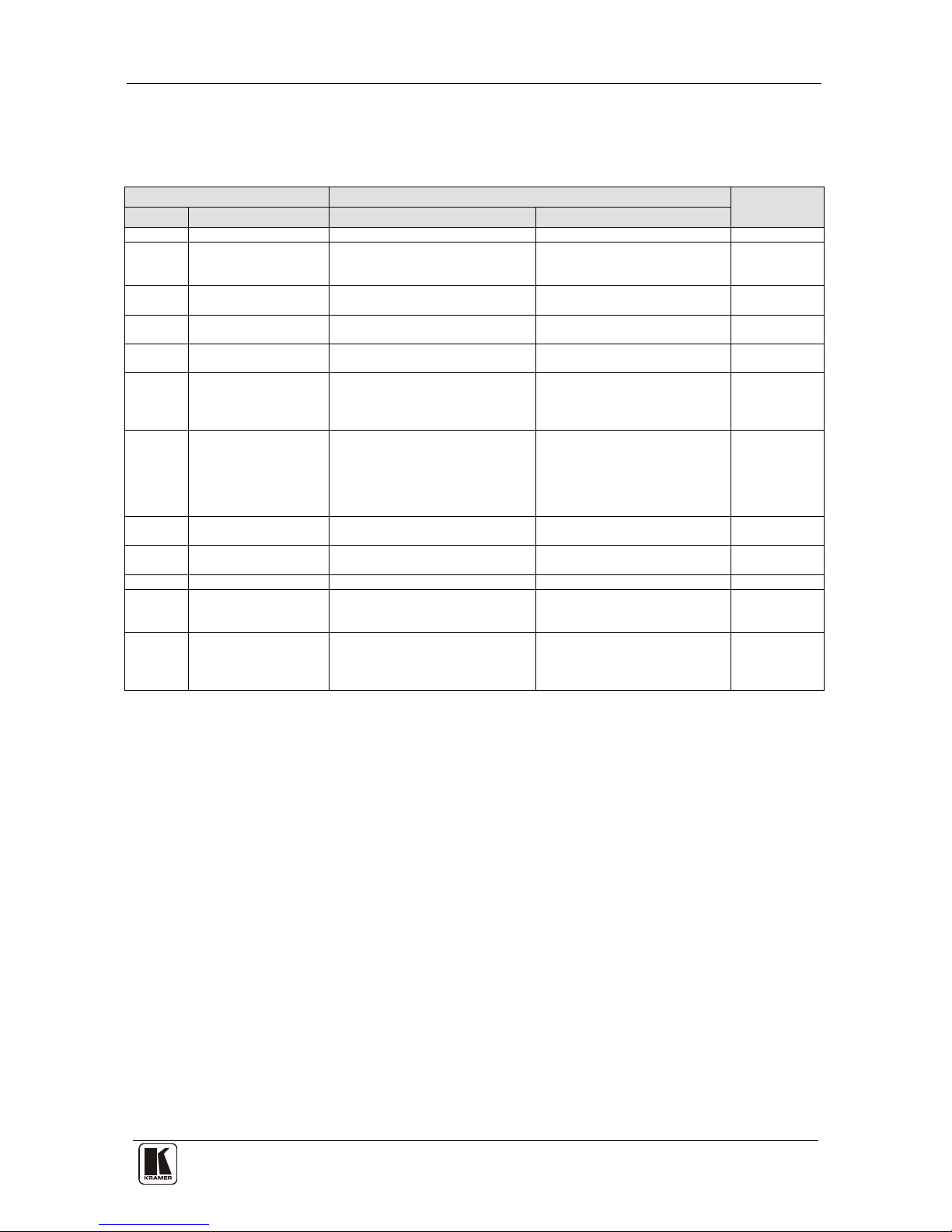
Table 10: Instruction Codes for Protocol 2000
Note: All values in the table are decimal, unless otherwise stated.
INSTRUCTION
DEFINITION FOR SPECIF IC I NST RUCTI ON
NOTE
#
DESCRIPTION
INPUT
OUTPUT
0
RESET DEVICE
0 0 1
1 SWITCH VIDEO Set equal to video input which is to
be switched
(0 = disconnect)
Set equal to video output which is
to be switched
(0 = to all the outputs)
2, 15
3 STORE VIDEO
STATUS
Set as SETUP # 0 - to store
1 - to delete
2, 3, 15
4 RECALL VID EO
STATUS
Set as SETUP # 0 2, 3, 15
5 REQUEST STATUS
OF A VIDEO OUTPUT
Set as SETUP # Equal to output number whose
status is required
4, 3
15 REQUEST WHETHER
SETUP IS DEFINED /
VALID INPUT IS
DETECTED
SETUP #
or
Input #
0 - for checking if setup is defined
1 - for checking if input is valid
8
16 ERROR / BUSY For invalid / valid input (i.e.
OUTPUT byte = 4 or OUTPUT byte
= 5),
this byte is set as the input #
0 - error
1 - invalid instruction
2 - out of range
3 - machine busy
4 - invalid input
5 - valid input
9, 25
30
LOCK FRONT PANEL
0 - Panel unlocked
1 - Panel locked
0 2 31
REQUEST WHETHER
PANEL IS LOCKED
0 0 16
56
CHANGE TO ASCII
0
3 – Protocol 3000l
19
61 IDENTIFY MACHINE 1 - video machine name
3 - video software version
0 - Request first 4 digits
1 - Request first suffix
13
62 DEFINE MACHINE 1 - number of inputs
2 - number of outputs
3 - number of setups
1 - for video
3 - for SDI
4 - for remote panel
5 - for RS-422 controller
14
NOTES on the above table:
NOTE 1 - When the master switcher is reset, (e.g. when it is turned on), the reset code is sent to the PC. If this code is sent to
the switchers, it will reset according to the present power-down settings.
NOTE 2 - These are bi-directional definitions. That is, if the switcher receives the code, it will perform the instruction; and if
the instruction is performed (due to a keystroke operation on the front panel), then these c odes are sent. For example, if th e
HEX code
01 85 88 83
was sent from the PC, then the switcher (machine 3) will switc h input 5 to outpu t 8. If the user switched input 1 to output 7
via the front panel keypad, then the switcher will send HEX codes:
41 81 87 83
to the PC.
When the PC sends one of the commands in this group to the switcher, then, if the instruction is valid, the switcher replies by
sending to the PC the same four bytes that it was sent (except for the first byte, where the DESTINATION bit is set high).
NOTE 3 - SETUP # 0 is the present setting. SETUP # 1 and higher are the settings saved in the switcher's memory, (i. e. those
used for Store and Recall).
NOTE 4 - The reply to a "REQUE ST" instruction is as follows: the same instruction an d INPUT codes as were sent are
returned, and the OUTPUT is assigned the value of the requested p arameter. The replies to instructions 10 and 11 are as per
the definitions in instructions 7 and 8 respectively. For example, if the present status of machine nu mber 5 is breakaway
setting, then the reply to the HEX code
0B 80 80 85
would be HEX codes
4B 80 81 85
Page 40

KRAMER: SIMPLE CREATIVE TECHNOLOGY
Kramer Protoc ol 2000
36
NOTE 8 - The reply is as in TYPE 3 abo ve, except that here the OUTPUT is assigned with the value 0 if the setup is not
defined / no valid input is detected; or 1 if it is defined / valid input is detected.
NOTE 9 - An error code is returned to the PC if an invalid instruction code was sent to the switcher, or if a parameter
associated with the instruction is out of range (e.g. trying to save to a setup greater than the highest one, or trying to switch an
input or output greater than the highest one d efined). This code is also returned to the PC if an RS-232 instruction is sent
while the machine is being programmed via the front panel. Reception of this code by the switcher is not valid.
NOTE 13 - This is a request to identify the switcher/s in the system. If the OUTPUT is set as 0, and the INPUT is set as 1, 2,
5 or 7, the machine will send its na me. The re ply is the deci mal value of the INPUT and O UTPUT. For exa mple, for a 2 216,
the reply to the request to send the machine name would be (HEX codes):
7D 96 90 81 (i.e. 128
dec
+ 22
dec
for 2nd byte, and 128
dec
+ 16
dec
for 3rd byte).
If the request for identification is sent with the INPUT set as 3 or 4, the appropriate machine will send its software version
number. Again, the reply would be the d ecimal value of the INPUT and OUTPUT - the INPUT representing the nu mber in
front of the decimal point, and the O UTPUT representing the number after it. For example, for version 3.5, the reply to the
request to send the version number would be (HEX codes):
7D 83 85 81 (i.e. 128
dec
+ 3
dec
for 2nd byte, 128
dec
+ 5
dec
for 3rd byte).
If the OUTPUT is set as 1, then the ASCII coding of the letterin g following the machine’s name is sent. For exa mple, for the
VS-7588YC, the reply to the request to send the first suffix would be (HEX codes):
7D D9 C3 81 (i.e. 128
dec
+ ASCII for “Y”; 128
dec
+ ASCII for “C”).
NOTE 14 - The nu mber of inputs and outputs refers to the sp ecific machine which is bein g addressed, not to the system. For
example, if six 16X16 matrices are configured to make a 48X32 system (48 inputs, 32 outputs), the reply to the HEX code
3E 82 81 82 (i.e. request the number of outputs)
would be HEX codes
7E 82 90 82
i.e. 16 outputs
NOTE 15 – When the OVR bit (4
th
byte) is set, then the “video” commands have universal meaning. For exa mple, instruction
1 (SWITCH VIDEO) will cause all units (inc luding data, etc.) to switch. Similarly, if a machine is in “FOLLOW” mode, it
will perform any “video” instruction.
NOTE 16 - The reply to the “REQUEST WHETHER P ANEL IS LOCKED” is as in NOTE 4 above, except that here the
OUTPUT is assigned with the value 0 if the panel is unlocked, or 1 if it is locked.
NOTE 19 – After this instruction is sent, the unit will respond to the ASCII command set de fined by the OUTPUT byte. The
ASCII command to operate with the HEX command set must be sent in order to return to working with HEX codes.
NOTE 25 – For units which detect the validity of the video inputs, Instruction 16 will be sent whenever the unit detects a
change in the state of an input (in real-time).
For example, if input 3 is detected as invalid, the unit will send the HEX codes
10 83 84 81
If input 7 is detected as valid, then the unit will send HEX codes
10 87 85 81.
Page 41

37 37
LIMITED WARRANTY
WHO IS PROTECTED?
WHA T IS COVERED AND WHA T IS NOT COVERE D
WHA T WE WILL P A Y FOR A ND WHA T W E WILL NOT P A Y FOR
HOW YOU CAN GET WARRANTY SERVICE
LIMITA TION OF IMPLIED WARRANTIES
EXCLUSION OF DAMAGES
CAUTION!
Kramer Electronics (hereafter ) warrants this pr oduct free f rom defects i n mater ial and workma nship unde r the
following terms.
Kramer
HOW LONG IS THE W ARRANTY
Labor and parts are warranted for seven years from the date of the first customer purchase.
Only the first purchase customer may enforce this warranty.
W e will p ay labor and ma teria l expen ses for cover ed item s. W e wi ll not pa y for th e fol lowing:
The li abil ity of Krame r for any e ffe ct ive pr oduc ts is l imi ted t o the repair or re pla ceme nt of the pro duc t at ou r op tion. Kram er sha ll
not be liabl e for:
This wa rran ty give s you spec ific l egal rights , and yo u may al so have other r ights, w hich va ry fr om place to place.
All produ cts ret urned t o Krame r for service must hav e pri or approv al. This ma y be obt ained f rom you r deal er.
This e quipm ent has b een tes ted to determi ne co mpliance with t he requ iremen ts of:
EN-50 081: "Electr omagne tic co mpat ibility (EMC);
generic emission standard.
Residenti al, co mmerc ial and l ight ind ustry "
EN-50 082: "Electr omagne tic co mpat ibility (EMC) ge neric immuni ty sta ndard.
Part 1 : Reside ntia l, comm ercial and lig ht indus try e nviro nment".
CFR-47: FCC* Rules and Regulations:
Part 15 : “Ra d io frequency devices
Subpart B Unintentional radiators”
Except as below, this warranty covers all defects in material or workmanship in this product. The following are not covered
by the warranty:
1. Any product which is not distributed by Kramer, or which is not purchased from an authorized Kramer dealer. If you are
uncertain as to whether a dealer is authorized, please contact Kramer at one of the agents listed in the Web site
www.kramerelectronics.com.
2. Any product, on which the serial number has been defaced, modified or removed, or on which the WARRANTY VOID
TAMPERED sticke r ha s be en torn,
3. Damag e, dete riorat ion or malfunc tion r esulti ng from:
i) Accident, misuse, abuse, neglect, fire, water , ligh tning o r other acts of nature
ii) Produ ct modi ficati on, or f ailu re to foll ow in structi ons s upplied with t he produ ct
iii) Rep air o r atte mpted re pair by a nyone not au thoriz ed by Kra mer
iv) Any ship ment o f the pr oduct (claim s must b e pres ented to the carr ier)
v) Removal or i nstall ation of the produc t
vi) Any other cause, which does not relate to a product defect
vii)Cartons, e quipm ent encl osure s, cabl es or accesso ries use d in c onjunc tion wi th the p roduct
1. Removal or insta llatio ns char ges .
2. Costs of initial technical adjustments (set-up), including adjustment of user controls or programming. These costs are the
respon sibi lity of the Kram er deal er fr om whom t he produ ct wa s purcha sed.
3. Shipping cha rges .
1. To obtain service on you product, you must take or ship it prepaid to any authorized Kramer service center.
2. Whenever warranty service is required, the original dated invoice (or a copy) must be presented as proof of warranty
coverage, and should be included in any shipment of the product. Please also include in any mailing a contact name,
company, address, and a description of the problem(s).
3. For the name of the nearest Kramer authorized service center, consult your authorized dealer.
All implied warranties, including warranties of merchantability and fitness for a particular purpose, are limited in duration to
the length of this warranty.
1. Damage to othe r prop erty ca used by de fect s in this produc t, dama ges base d upon i nconven ienc e, loss of use of the produ ct, los s
of time, commercial lo ss; o r:
2. Any other d am ages , whe the r i ncide nta l, c onse quen ti al o r oth er wise. S ome co un tries may n ot all ow limi tati on s on how l on g an
implied warranty lasts and/or do not allow the exclusion or limitation of incidental or consequential damages, so the above
limit ation s and exc lusio ns may no t apply to yo u.
Servicing the machines can only be done by an authorized Kramer technician. Any user who makes changes or
modifications to the unit without the expressed approval of the manufacturer will void user authority to operate the
equipment.
Use th e suppl ied DC p ower sup ply t o feed p ower to t he mach ine.
Please use recommended interconnection cables to connect the machine to other components.
IF reattached, removed or otherwise interfered with.
* FCC and CE appro ved usin g STP cable ( for twist ed pai r produc ts)
NOTE:
Part 1 :
Page 42

Kramer Electronics, Ltd.
Web site: www.kramerelectronics.com
E-mail: [email protected]
P/N: 2900-000630 REV 2
For the latest information on our products and a list of Kramer
distributors, visit our Web site: www.kramerelectronics.com
where updates to this user manual may be found.
We welcome your questions, comments and feedback.
Caution
Safety Warning:
Disconnect the unit from the power supply before
opening/servicing.
 Loading...