

Page 1

KR AM ER ELECTR ONICS LTD .
U SER M ANUAL
M ODEL:
VS-88DT
H DM I/ HDBT M atrix S w itcher
P/N: 2900-3 00275 Rev 4
Page 2
Page 3

Contents
1 Introduction 1
2 Getting Started 2
2.1 Achieving the Best Performance 2
2.2 Safety Instruc tions 2
2.3 Using TP cables 3
2.4 Recycling Kramer Products 3
3 Overview 4
3.1 About HDBaseT™ Technology 5
4 Defining the VS-88DT HDMI/HDBT Matrix Switcher 6
5 Installing the VS-88DT in a Rack 9
6 Connecting the VS-88DT 10
6.1 Connecting a Serial Controller to the VS-88DT 11
6.2 Connecting to the VS-88DT via Ethernet 11
7 Operating the VS-88DT 15
7.1 Switching Inputs to Outputs 15
7.2 Storing and Recalling Preset Configurations 16
7.3 Acquiring an EDID 17
7.4 Cancelling One or All Outputs 17
7.5 Resetting the Device to Factory Default Configuration 18
7.6 Locking and Unlocking the Front Panel 19
7.7 RS-232 Data Routing over HDBaseT 19
8 Configuring the VS-88DT 20
8.1 Using the Menu 20
8.2 Selecting the HDBaseT or HDMI Outputs 22
8.3 Selecting DHCP 22
8.4 Configuring the IP Network Address 23
8.5 Resetting the VS-88DT t o Factory Default Configurat i on 24
9 Operating the VS-88DT Remotely Using the Web Pages 25
9.1 Switching Page 25
9.2 Device Settings Page 29
9.3 Authentication Page 30
9.4 RS-232 Routing Page 32
9.5 EDID Page 33
9.6 About Page 34
10 Wiring the DGKat TP RJ-45 Connectors 35
11 Updating the Firmware 36
12 Technical Specifications 38
13 Default Parameters 39
13.1 Default Communication Parameters 39
14 Kramer Protocol 40
14.1 Kramer Protocol 3000 Syntax 40
14.2 Kramer Protocol 3000 Commands 43
VS-88DT – Contents
i
Page 4

Figures
Figure 1: VS-88DT HDMI/HDBT Matrix Switcher Front Panel 6
Figure 2: VS-88DT HDMI/HDBT Matrix Switcher Rear Panel 8
Figure 3: Connecting the VS-88DT HDMI/HDBT Matri x Switcher 10
Figure 4: Local Area Connection Properties Window 12
Figure 5: Internet Protocol Version 4 Properties Window 13
Figure 6: Internet Protocol Properties Window 14
Figure 7: Login Page 25
Figure 8: Switching Page 26
Figure 9: Switching Button Details 27
Figure 10: Input Properties Popup 27
Figure 11: Output Properties Popup 28
Figure 12: Device Settings Page 30
Figure 13: Authentication Page 31
Figure 14: RS-232 Routing Page 32
Figure 15: EDID Page 33
Figure 16: About Page 34
Figure 17: TP Pinout Wiring 35
ii
VS-88DT – Contents
Page 5

VS-88DT - Introduction
1 Introduction
Welcome to Kramer Electronics! Since 1981, Kramer Electronics has been
providing a world of unique, creative, and affordable solutions to the vast range of
problems that confront the video, audio, presentation, and broadcasting
professional on a daily basis. In recent years, we have redesigned and upgraded
most of our line, making the best even better!
Our 1,000-plus different models now appear in 11 groups that are clearly defined
by function: GROUP 1: Distribution Amplifiers; GROUP 2: Switchers and Routers;
GROUP 3: Control Systems; GROUP 4: Format/Standards Converters; GROUP
5: Range Extenders and Repeaters; GROUP 6: Specialty AV Products; GROUP
7: Scan Converters and Scalers; GROUP 8: Cables and Connectors; GROUP 9:
Room Connectivity; GROUP 10: Accessories and Rack Adapters and GROUP 11:
Sierra Products.
Congratulations on purchasing your VS-88DT HDMI/HDBT Matrix Switcher which
is ideal for:
• Conference room presentations
• Advertising applications
1
Page 6

VS-88DT - Getting Started
Caution:
Warning:
i
!
!
2 Getting Started
We recommend that you:
• Unpack the equipment carefully and save the original box and packaging
materials for possible future shipment
• Review the contents of this user manual
Go to www.kramerav.com/downloads/VS-88DT
to check for up-to-date user manuals, application programs, and to check if
firmware upgrades are available (where appropriate).
2.1 Achieving the Best Performance
To achieve the best performance:
• Use only good quality connection cables (we recommend Kramer high-
performance, high-resolution cables) to avoid interference, deterioration in
signal quality due to poor matching, and elevated noise levels (often
associated with low quality cables)
• Do not secure the cables in tight bundles or roll the slack into tight coils
• Avoid interference from neighboring electrical appliances that may adversely
influence signal quality
• Position your Kramer VS-88DT away from moist ure, excess i ve sunlight and
dust
This equipment is to be used only inside a building. It may only be
connected to other equipment that is installed inside a building.
2.2 Safety Instructions
Warning:
Warning:
2
There are no operator serviceable parts inside the unit
Use only the power cord that is supplied with the unit
Do not open the unit. High voltages can cause
electrical shock! Servicing by qualified personnel only
Disconnect the power and unplug the unit from the wall
before installing
Page 7

VS-88DT - Getting Started
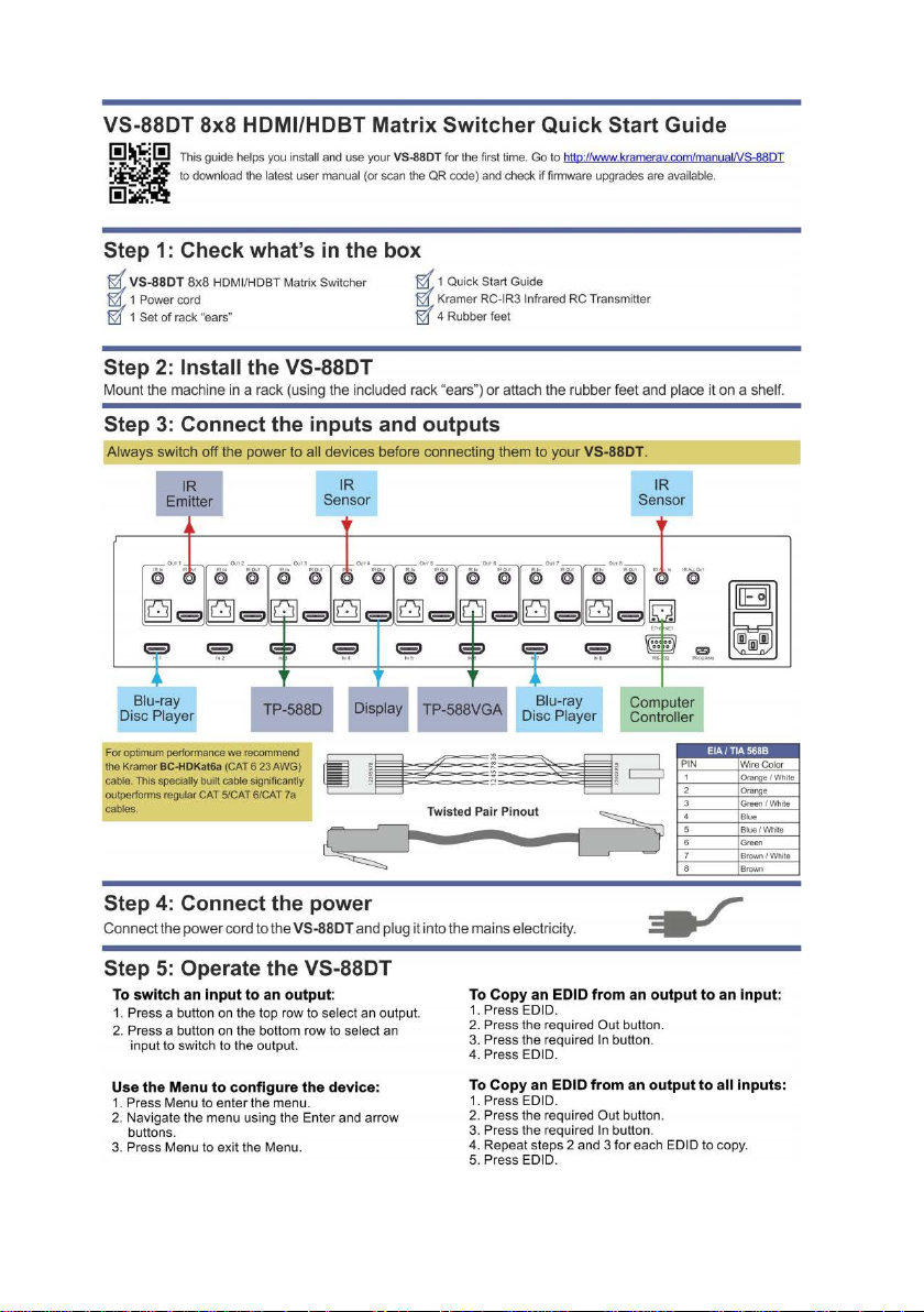
2.3 Using TP cables
Kramer engineers have developed a special twisted pair cable to best match our
HDBaseT products, the Kramer BC−HDKat6a (CAT 6 23 AWG) cable. This
specially built cable significantly outperforms regular CAT 5/CAT 6/CAT 7a cables.
2.4 Recycling Kramer Products
The Waste Electrical and Electronic Equipment (WEEE) Directive 2002/96/EC
aims to reduce the amount of WEEE sent for disposal to landfill or incineration by
requiring it to be collected and recycled. To comply with the WEEE Directive,
Kramer Electronics has made arrangements with the European Advanced
Recycling Network (EARN) and will cover any costs of treatment, recycling and
recovery of waste Kramer Electronics branded equipment on arrival at the EARN
facility. For details of Kramer’s recycling arrangements in your particular country
go to our recycling pages at www.kramerav.com/support/recycling/
.
3
Page 8

VS-88DT - Overview
3 Overview
The high-quality Kramer VS-88DT is a n HDMI/HDBT Matrix Switcher that accepts
up to eight HDMI signals and routes any or all of them to any or all eight HDMI
outputs or HDBaseT for connection to compatible receivers, for example, the
TP-588D and TP-588VGA.
The VS-88DT features:
• Eight HDMI and nine IR inputs
• Eight HDMI, eight HDBaseT and nine IR outputs
• Bandwidth up to 6.75Gbps (2.25Gbps per video channel)
• EDID Capture—copies and stores the EDID from a display device
• Hot-plug Detect (HPD)
• HDBaseT range up to 100m (328ft)
• RS-232 data tunneling over HDBaseT
• HDCP support
• HDTV compatibility
• Support for HDMI – 3D, Deep Color, x.v.Color™, Lip Sync , Dolby
Dolby Digital Plus, DTS−HD
• A non-volatile memory for matrix configuration
• A store and recall facility for preset configurations
• Automatic output shutdown if no input signal is detected after a configurable
idle period
• An LCD display for easy configuration and operation
• Remote control using serial commands (over RS-232 and Ethernet) and
built-in, browser-based Web pages
• Support for Kramer Protocol 3000
• A lock button to prevent unwanted tampering with the settings
• 2U height that fits a standard 19” professional rack enclosure
4
®
and linear PCM 7.1 surround sound
®
TrueHD,
Page 9

VS-88DT - Overview
You can control the VS-88DT using the front panel buttons, or remotely via:
• Built-in, embedded Web pages using a standard Web browser over Ethernet
• RS-232 serial commands transmitted by a touch screen system, PC or other
serial controller
• The Kramer infrared remote control transmitter
3.1 About HDBaseT™ Technology
HDBaseT™ is an advanced all-in-one connectivity technology (supported by the
HDBaseT Alliance). It is particularly suitable in the consumer home environment
as a digital home networking alternative where it enables you to replace numerous
cables and connectors by a single LAN cable used to transmit, for example,
uncompressed, full, high definition video, audio and IR as well as various control
signals.
5
Page 10
#
Feature
Function
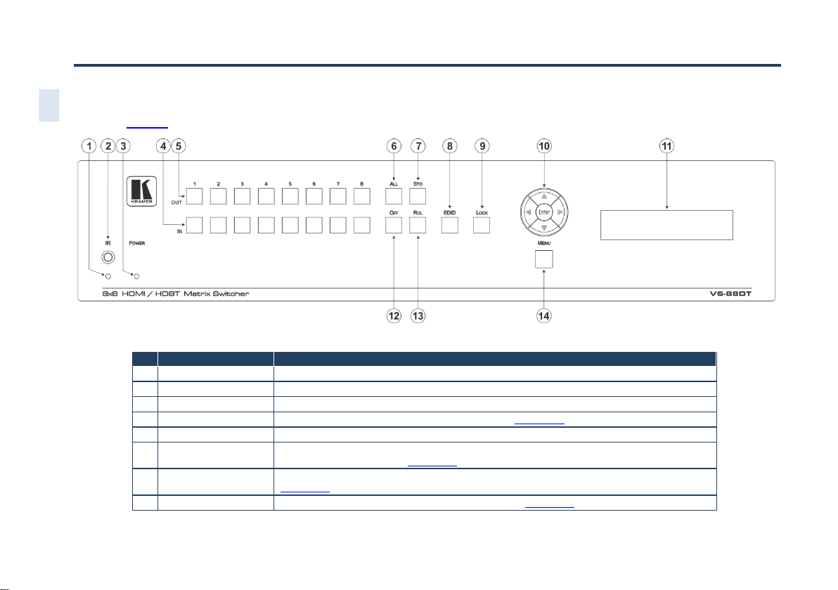
1
IR LED
Lights yellow when receiving an IR signal
2
IR Sensor
IR receiver for remote control
3
POWER LED
Lights green when the devic e is pow er ed on
4
IN 1~8
Press to select an input after selecting an output (see Section 7.1)
5
OUT 1~8
Press to switch, followed by an input or OFF
6
ALL Button
Press, followed by an Input to switch the Input to all outputs or press followed by the Off button to
disconnect all switches, (see Section 7.4)
7
STO Button
Press to store a preset configuration followed by the preset number in which to save it (see
Section 7.2)
8
EDID Button
Press to copy the EDID from an Output to an Input (see Section 7.3)
4 Defining the VS-88DT HDMI/HDBT Matrix Switcher
6
Figure 1 defines the front panel of the VS-88DT.
VS-88DT – Overview
Figure 1: VS-88DT HDMI/HDBT Matrix Switcher Front Panel
Page 11

#
Feature
Function
9
LOCK Button
Press and hold to lock the front panel b utto ns , (se e Section 7.6). Press and hold again to unlock
10
Menu Navigation Pad
Use the Enter, up (▲), down (▼), left (◄) and right (►) buttons to navigate the menu, and modify
parameters or values (se e Section 8.1)
11
LCD Readout
(20 char x 2 lines)
Displays either the input/output resolution currently selected or the menu during configuration
12
OFF Button
Press after an output button to cancel the currently selected outputs. Press after the All button to
cancel all currently switched outputs (see Section 7.4)
13
RCL Button
Press, followed by a preset number to r ecal l the preset configuration (see Section 7.2)
14
MENU Button
Press to enter the Menu and move one level back when the menu is displayed (see Section 8.1)
VS-88DT – Defining the VS-88DT HDMI/HDBT Matrix Switcher
7
Page 12
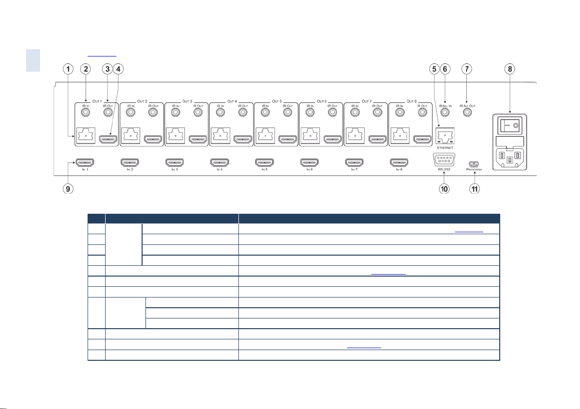
#
Feature
Function
1
RJ-45 HDBaseT Connector
Connect to compatible HDBaseT devices, for example, TP-588D (see Section 6)
2
IR IN 3.5mm Mini Jack
Connect to IR sensors
3
IR OUT 3.5mm Mini Jack
Connect to IR blasters
4
HDMI Connector
Connect HDMI acceptors
5
ETHERNET RJ-45 Connector
Connect to a PC controller via a LAN (see Section 6.2)
6
IR ALL IN 3.5mm Mini Jack
Connect to an IR sensor
7
IR ALL OUT 3.5mm Mini Jack
Connect to an IR blaster
Power Socket
Connect the mains power cord
Fuse
AC mains supply protection fuse
Power Switch
Turns the device on and off
9
IN 1~8 HDMI Connectors
Connect to HDMI sources
10
RS-232 9-pin D-sub Serial Port
Connect to a serial controller (see Section 6.1)
11
PROGRAM Mini USB Connector
For performing firmware upgrade
8
VS-88DT – Defining the VS-88DT HDMI/HDBT Matrix Switcher
Figure 2 defines the rear panel of the VS-88DT.
Figure 2: VS-88DT HDMI/HDBT Matrix Switcher Rear Panel
OUT 1~8
8 AC Mains
Page 13
VS-88DT - Installing the VS-88DT in a Rack
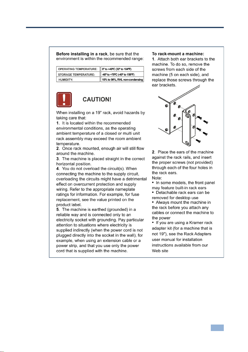
5 Installing the VS-88DT in a Rack
9
Page 14
VS-88DT - Connecting the VS-88DT
i
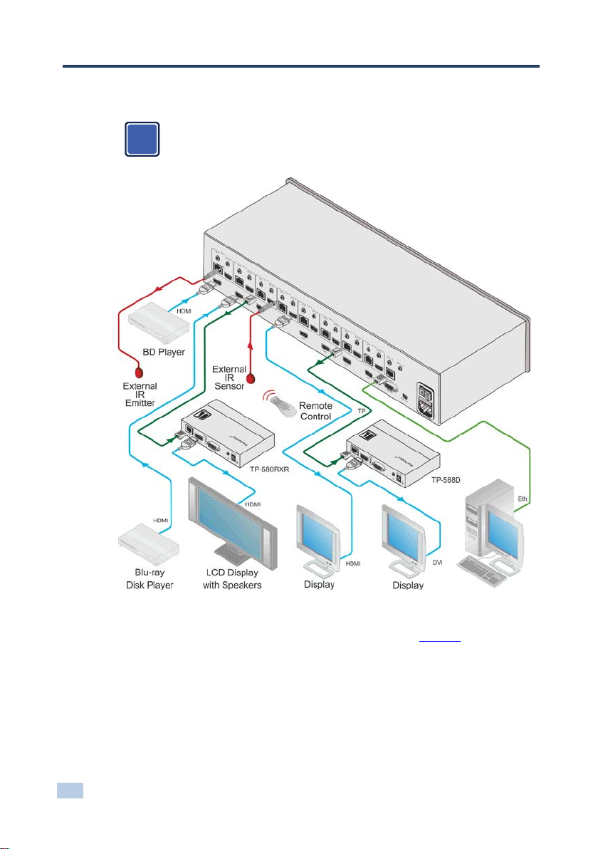
6 Connecting the VS-88DT
Switch off the power to all devices before connecting them t o your
VS-88DT. After connecting your VS-88DT, connect its power and then
switch on the power to the other devices.
Figure 3: Connecting the VS-88DT HDMI/HDBT Matrix Switcher
To connect the VS-88DT as illustrated in the example in Figure 3:
1. Connect the HDMI sources, (for example, Blu-ray disc players) to the HDMI
In 1 and In 2 connectors.
2. Connect an external I R sensor to the In 4 I R In 3.5mm m ini jack .
3. Connect the Out 1 IR 3.5mm mini jack to an external IR transmitter.
10
Page 15

VS-88DT - Connecting the VS-88DT
4. Connect the Out 4 HDMI connector to an HDMI acceptor, (for example, a
display).
5. Connect the Out 3 TP RJ-45 HDBT connector to a compatible HDBT
receiver, (for example, the TP-580Rxr), and connect the HDMI output of the
TP-580Rxr to a display.
6. Connect the Out 7 TP RJ-45 HDBT connector to a compatible HDBT
receiver, (for example, the TP-588D), and connect the DVI output of the
TP-588D to a display.
7. Connect a controller via either RS -232 or a LAN to the Ethernet RJ-45
connector.
6.1 Connecting a Serial Controller to the VS-88DT
You can connect to the VS-88DT via an RS-232 connection using, for example, a
PC. For information about routing RS-232 data over HDBaseT, see Section 7.7
To connect to the VS-88DT via RS-232:
• Connect the 9-pin D-sub connector on the rear panel of the VS-88DT (pin 5
to pin 5, pin 2 to pin 3, pin 3 to pin 2) to the RS 232 9-pin D-sub port on your
PC
.
6.2 Connecting to the VS-88DT via Ethernet
You can connect to the VS-88DT via Ethernet using either of the following
methods:
• Directly to the PC using a crossover cable (see Section 6.2.1
• Via a network hub, switch, or router, using a straight-through cable (see
Section 6.2.2
Note: If you want to connect via a router and your IT system is based on IPv6,
speak to your IT department for specific installation instructions.
)
)
11
Page 16
VS-88DT - Connecting the VS-88DT
i
6.2.1 Connecting the Ethernet Port Directly to a PC
You can connect the Ethernet port of the VS-88DT directly to the Ethernet port on
your PC using a crossover cable with RJ-45 connectors.
This type of connection is recommended for identifying the VS-88DT
with the factory configured default IP address.
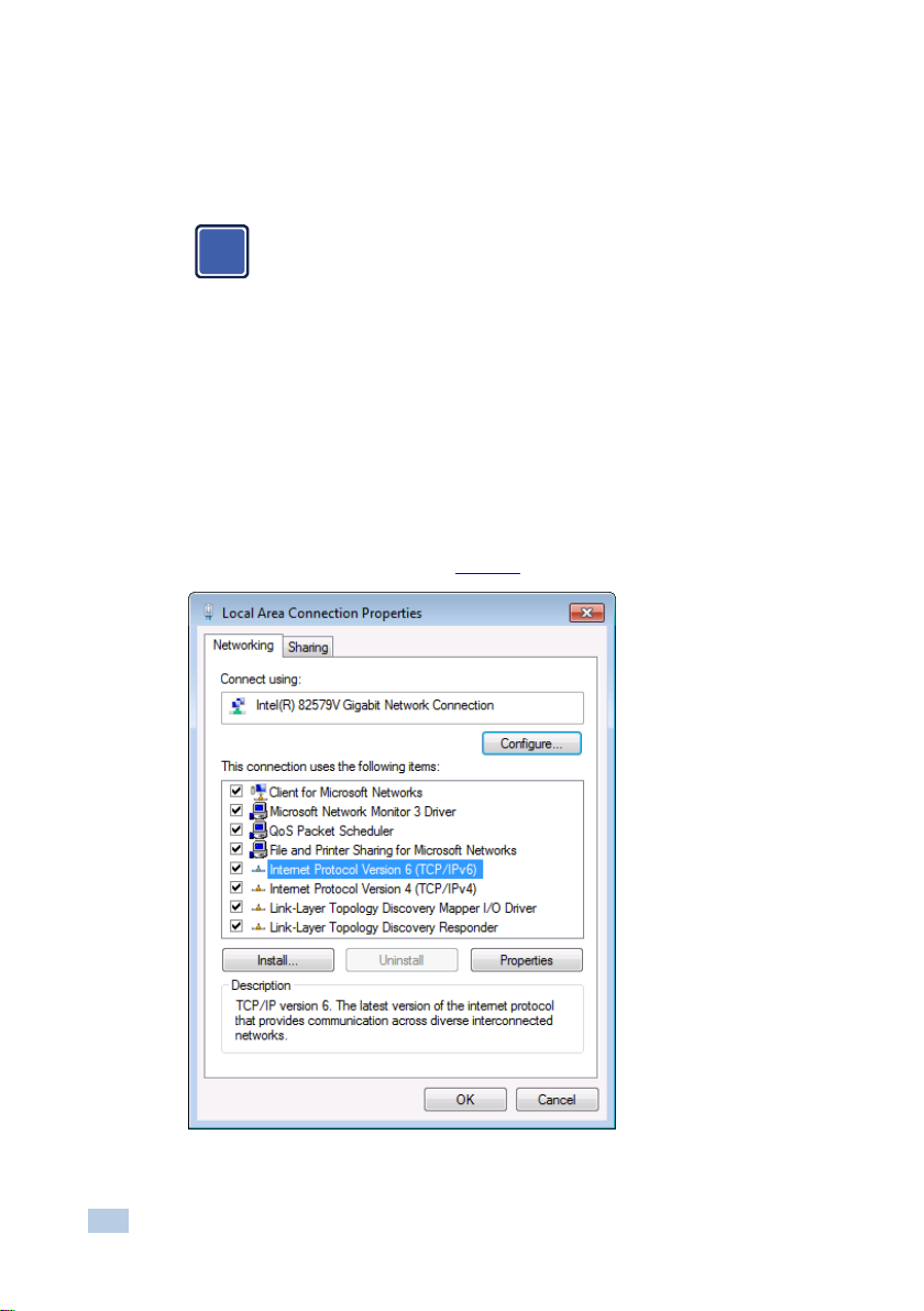
After connecting the VS-88DT to the Ethernet port, configure your PC as follows:
1. Click Start > Control Panel > Network and Sharing Center.
2. Click Change Adapter Settings.
3. Highlight the network adapt er you want to use to connect to the device and
click Change settings of this connection.
The Local Area Connection Properties window for the selected network
adapter appears as shown in Figure 4
.
Figure 4: Local Area Connection Properties Window
12
Page 17

VS-88DT - Connecting the VS-88DT
4. Highlight Internet Protocol Version 4 (TCP/IPv4).
5. Click Properties.
The Internet Protocol Properties window appears as shown in Figure 5
.
Figure 5: Internet Protocol Version 4 Properties Window
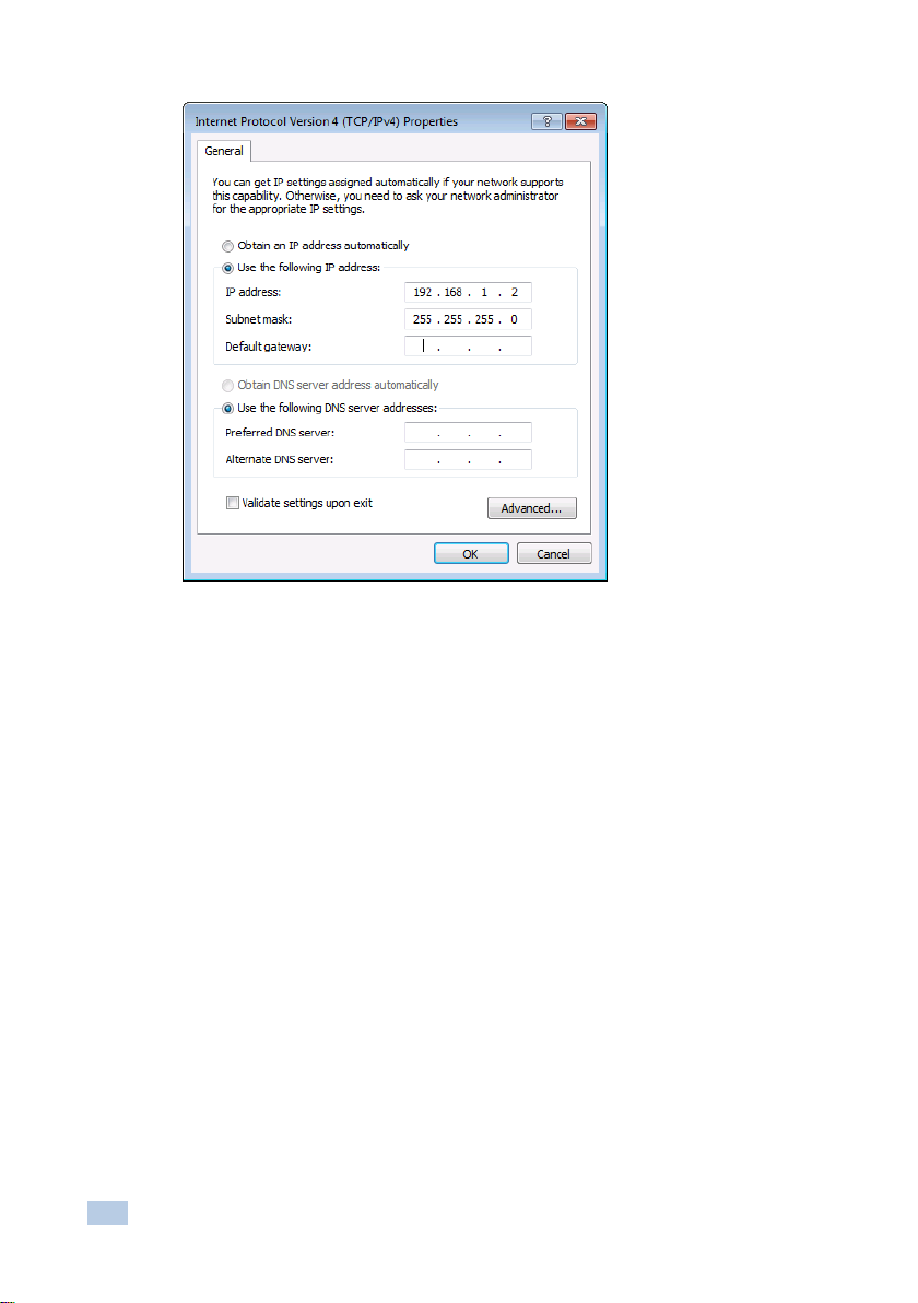
6. Select Use the following IP Address for static IP addressing and fill in the
details as shown in Figure 6
For TCP/IPv4 you can use any IP address in the range 192.168.1.1 to
192.168.1.255 (excluding 192.168.1.39) that is provided by your IT
department.
.
13
Page 18
VS-88DT - Connecting the VS-88DT
Figure 6: Internet Protocol Properties Window
7. Click OK.
8. Click Close.
6.2.2 Connecting the Ethernet Port via a Network Hub or Switch
You can connect the Ethernet port of the VS-88DT to the Ethernet port on a
network hub or using a straight-through cable with RJ-45 connectors.
14
Page 19

VS-88DT - Operating the VS-88DT
O: 1 2 3 4 5 6 7 8
I: 3 0 1 2 4 5 2 8
7 Operating the VS-88DT
When the VS-88DT is powered on, the following is displayed briefly on the LCD
display:
KRAMER ELEC
8X8 HDMI/HDBT Matrix
Following the self-test the current switching configuration is displayed, an example
of which is shown below. The top row indicates the output port and the bottom row
indicates which input port is switched to the output port displayed directly above it.
An input port showing 0 (zero) indicates that the output port has no input switched
to it.
Note: If there is no button activity during any procedure for approximately 30
seconds, the procedure is aborted and the display reverts back to the Input/Output
display.
7.1 Switching Inputs to Outputs
You can switch:
• Individual inputs to individual outputs
• One input to all outputs
To switch an output to an input, (for example, Input 7 to Output 3):
1. Press Out 3.
The Output button lights red.
2. Press In 7.
The Input button lights red and the switch is performed.
15
Page 20

VS-88DT - Operating the VS-88DT
To switch one input to all outputs, (for example, Input 2 to all outputs):
1. Press All.
The All button lights red.
2. Press In 2.
The Input 2 button lights and Input 2 is switched to all outputs.
7.2 Storing and Recalling Preset Configurations
You can store up to eight pres et configurat i ons f or instant recal l. T he top row of
output buttons relate to presets one to eight.
To store the current configuration in preset 5:
1. Press Sto.
2. Press Out 5.
The selection is displayed in the readout.
3. Press Sto.
The current configuration is stored in preset 5.
16
To recall preset 8:
1. Press Rcl.
2. Press Out 8.
The selection is displayed in the readout.
3. Press Rcl.
The configuration stored in preset 8 is recalled.
Page 21

VS-88DT - Operating the VS-88DT
7.3 Acquiring an EDID
You can acquire the EDID from an output and assign it to either one or all inputs.
To acquire the EDID from an output and store it on one input, (for example,
Output 5 to Input 8):
1. Press EDID.
The button lights red.
2. Press Out 5.
3. Press In 8.
4. Press EDID.
The button no longer lights and the EDID from Output 5 is stored in Input 8.
7.4 Cancelling One or All Out puts
The Off button is used to cancel one or all currently switched outputs.
To cancel one currently switched output, (for example, Output 7):
1. Press Out 7.
2. Press Off.
To cancel all currently switched outputs:
1. Press All.
2. Pr ess Off.
17
Page 22

VS-88DT - Operating the VS-88DT
7.5 Resetting the Device to Factory Default Configuration
The VS-88DT can be reset to factory default configuration either by sending a
Protocol 3000 command or by using the front panel buttons.
To reset the device to the factory default configuration by sending a P3000
command:
1. Connect from a PC to the VS-88DT via the serial port using the following
parameters:
115200, 8, 1, none
2. Send the P3000 command to reset the device to factory default (see
Section 14.2
After a few seconds the VS-88DT is reset to factory defaul t.
To reset the device to the factory default configuration using the front panel
buttons:
1. Press the Menu button.
The Menu button lights and the first option on the menu appears.
).
18
2. Use the up (▲) and down (▼) arrows on the keypad to scroll to the RESET
TO DEFAULT option.
3. Press the Enter button.
The Reset to Default No and Yes options appear.
4. Use the left (◄) and right (►) arrows on the keypad to select Yes.
5. Press Enter.
After a few seconds the standby readout is displayed and the device is reset
to factory default.
Page 23

VS-88DT - Operating the VS-88DT
7.6 Locking and Unlocking the Front Panel
You can lock the front panel buttons to prevent unwanted key presses from
changing the current configuration.
To lock the front panel:
• Press and hold the Lock button.
The button lights, the Locked message is displayed briefly, and the front
panel buttons are locked. Pressing any button causes the Locked message
to display briefly and the Lock button to flash
To unlock the front panel:
• Press and hold the Lock button.
The button no longer lights and the front panel buttons are unlocked
7.7 RS-232 Data Routing over HDBaseT
The VS-88DT enables routing data from a source connected to the RS-232 serial
port to one of the HDBaseT outputs. This can be performed from the RS-232
Routing Web page (see Section 9.4
Section 14).
) or using the ROUTE command (see
For simulation purposes, the VS-88DT also enables routing the RS-232 data to all
the HDBaseT outputs, by chaining multiple ROUTE commands. For more
information on chaining multiple commands, see Section 14.1.6
Note: When RS-232 data routing is enabled, the RS-232 serial port cannot be
used for connecting a serial controller.
.
19
Page 24

VS-88DT - Configuring the VS-88DT
Parameter
Description
Options
Output 1~8:
Sets the required ou tpu ts
HDBT, HDMI
8 Configuring the VS-88DT
8.1 Using the Menu
The main menu comprises three sections:
• Interface Out (see Section 8.1.1
• RS-232 Routing (see Section 8.1.2)
• DHCP (see Section 8.1.3)
• Ethernet Statu s (see Section 8.1.4)
• FW version display (see Section 8.1.5)
• Reset to Default (see Section 8.1.6)
• Update Firmware (see Section 8.1.7)
Navigation through the menu is performed as follows:
• Menu—Enter the Menu or exit one level when in the Menu
• Enter—Select a parameter/value
• Up (▲) or Right (►)—scroll up through the parameter/value list
• Down (▼) or Left (◄)—scroll down through the parameter/value list
Note: If there is no button activity for approximately 30 seconds, the display
reverts back to the Input/Output display.
8.1.1 Interface Out Sub-menu
)
20
The parameters in the Interface Out sub-menu set the output signal format.
Default—HDBT
Page 25

VS-88DT - Configuring the VS-88DT
Parameter
Description
Options
OFF, ON
Turns the RS-232 routing on an d off
OFF, ON
Parameter
Description
Options
Default—OFF
IP Settings
Sets the IP network address
All valid IP addresses
Settings
addresses
Parameter
Description
IP Status:
Displays the TCP/IP address of the device
Netmask Status:
Displays the TCP/IP netmask of the device
Gateway Status:
Displays the TCP/IP gateway
MAC Address:
Displays the MAC address of the device
8.1.2 RS-232 Routing Sub-menu
The RS-232 Status sub-menu turns the RS-232 serial communication routing on
and off.
8.1.3 Network Settings Sub-menu
The Network Status sub-menu controls DHCP selection and IP network
parameters.
OFF, ON Turns DHCP on and off OFF, ON
Default—OFF
Netmask
Settings
Gateway
Sets the IP netmask All valid IP netmask
Sets the IP gateway All valid IP gateway
Note: When turning DHCP on, the device performs an automatic reset.
8.1.4 Ethernet Status Sub-menu
The parameters in the Ethernet Status sub-menu display the TCP/IP
communication parameters.
8.1.5 FW Version Display
Displays the firmware version similar to the following:
V1.1.1123+04A+1.0
addresses
21
Page 26

VS-88DT - Configuring the VS-88DT
Parameter
Description
NO, YES
Resets the device to default factory parameters
Parameter
Description
Update I/O FW:
Updates the I/O firmware
8.1.6 Reset to Default Sub-menu
8.1.7 Update Firmware Sub-menu
8.2 Selecting the HDBaseT or HDMI Outputs
To select the HDBaseT or HDMI outputs:
1. Press the Menu button to display the menu.
The menu is displayed.
2. Using the up (▲) or down (▼) button, move through the menu options until
the Interface Out: option is displayed.
3. Press Enter.
The HDBaseT and HDMI options are displayed.
4. Using the left (◄) or right (►) button, select either HDBaseT or HDMI.
5. Press Enter.
The change is saved.
8.3 Selecting DHCP
Note: Turning DHCP off does not de-encrypt encoded streams, it simply indicates
to the source that DHCP is not supported.
To select the DHCP:
1. Press the Menu button to display the menu.
The menu is displayed.
2. Using the up (▲) or down (▼) button, move through the menu options until
the Network Settings option is displayed.
22
Page 27

VS-88DT - Configuring the VS-88DT
3. Press Enter.
The DHCP On and OFF options are displayed.
4. Using the left (◄) or right (►) button, select either On or Off.
5. Press Enter.
The change is saved.
8.4 Configuring the IP Network Address
To configure the IP network address:
1. Press the Menu button to display the menu.
The menu is displayed.
2. Using the up (▲) or down (▼) button, move through the menu options until
the Network Settings option is displayed.
3. Press Enter.
The DHCP Settings option is displayed.
4. Using the up (▲) or down (▼) button, move through the menu options until
the IP Settings option is displayed.
5. Press Enter.
6. Using the left (◄) or right (►) button, move the cursor to the digit you wish
to change.
7. Using the up (▲) or down (▼) button, select the required digit.
8. Repeat steps 6 and 7 until the required address is displayed.
9. Press Enter.
The change is saved.
23
Page 28

VS-88DT - Configuring the VS-88DT
8.5 Resetting the VS-88DT to Factory Default Configuration
To reset the VS-88DT to factory default parameters:
1. Press the Menu button to display the menu.
The menu is displayed.
2. Using the up (▲) or down (▼) button, move through the menu options until
the Reset to Default: option is displayed.
3. Press Enter.
The NO and YES options are displayed.
4. Using the left (◄) or right (►) button, select YES.
5. Press Enter.
The device is reset to factory default parameters and automatically reboots.
24
Page 29

VS-88DT - Operating the VS-88DT Remotely Using the Web Pages
9 Operating the VS-88DT Remotely Using the
Web Pages
You can configure and control the VS-88DT using the embedded Web pages by
connecting via a Web browser over Ethernet. For a first time connection or if you
have authentication enabled the Login page shown in Figure 7
is displayed.
Figure 7: Login Page
If authentication is not enabled, click on the arrow. If authentication is enabled,
enter a valid user name and password and click on the arrow. The Switching page
shown in Figure 8
is displayed.
9.1 Switching Page
The Switching page allows you to:
• Switch inputs to outputs
• Edit the button name
• Select either the HDMI or HDBT output
• Mute the output
25
Page 30

VS-88DT - Operating the VS-88DT Remotely Using the Web Pages
• See what signal is present on the input and output
• See which input is switched to which output
26
Figure 8: Switching Page
Page 31

VS-88DT - Operating the VS-88DT Remotely Using the Web Pages
#
Item
Description
1
Eight output buttons
Click on the button to select an output
2
Mute button
Click to mute the output
3
Edit button
Click to open the button edit popup
4
Input number
Indicates which input is switched to this output
5
Eight input buttons
Click to select an input
6
Output number
Indicates the out put num b er
7
Signal type
Indicates the signal type present on the output
Figure 9: Switching Button Details
Figure 11 shows the Input button properties popup.
Figure 10: Input Properties Popup
27
Page 32

VS-88DT - Operating the VS-88DT Remotely Using the Web Pages
#
Item
Description
1
Input #1 properties
Displays the input you are currently editing
2
HDMI output label
Enter the text required for the HDMI input label
3
HDCP button
Click to enable/disable HDCP
4
Save button
Click to save changes to either of the labels
#
Item
Description
1
Output #2 properties
Displays the output you are currently editing
2
HDMI output label
Enter the text required for the HDMI output label
3
HDMI button
Click to enable the HDMI output
4
HDBaseT output label
The current HDBaseT output label
5
HDBaseT button
Click to enable the HDBaseT output
6
Save button
Click to save changes to either of the labels
Figure 11 shows the Output properties popup.
Figure 11: Output Properties Popup
28
Page 33

VS-88DT - Operating the VS-88DT Remotely Using the Web Pages
9.1.1 Updating the Firmware
To update the firmware:
1. Download the latest firmware file from www.kramerav.com
2. Click the Upload button.
The file browser window appears.
3. Browse to the firmware file.
4. Select the required file and click OK.
The new firmware is installed.
Note: Do not interrupt the procedure or the device may be rendered inoperable.
5. Wait until the device reboots automatically at the end of the procedure.
9.2 Device Settings Page
The Device Settings page allows you to:
• See the current IP settings
• Turn DHCP on and off
• Edit the IP settings for static IP
29
Page 34

VS-88DT - Operating the VS-88DT Remotely Using the Web Pages
Figure 12: Device Settings Page
9.3 Authentication Page
There are three levels of authentication:
• No username or password required to access any settings
• Access to all settings limited to entry with a valid username and password
• Access to only the serial port settings limited to entry with a valid username
and password
The Authentication page allows you to:
• Turn Web page authentication on and off
30
Page 35

VS-88DT - Operating the VS-88DT Remotely Using the Web Pages
• Set the Web page access username and password
• Set the Web page access logout timeout
• Turn serial port settings access on and off
• Set the serial port settings access username and password
• Set the serial port Web page logout timeout
Figure 13: Authentication Page
31
Page 36

VS-88DT - Operating the VS-88DT Remotely Using the Web Pages
9.4 RS-232 Routing Page
The RS-232 Routing page allows you to:
• Turn remote RS-232 routing on and off
• Select the HDBaseT output to which to route the RS-232 data
• Select the serial baud rate for each HDBaseT port
Figure 14: RS-232 Routing Page
32
Note: When RS-232 data routing is enabled, the RS-232 serial port cannot be
used for connecting a serial controller.
Page 37

VS-88DT - Operating the VS-88DT Remotely Using the Web Pages
9.5 EDID Page
The EDID page allows you to:
• Copy an EDID from:
The default EDID
Any HDBaseT output
Any input
An EDID stored in a file
• Copy an EDID to one or more inputs
Figure 15: EDID Page
33
Page 38

VS-88DT - Operating the VS-88DT Remotely Using the Web Pages
9.6 About Page
The About page displays the device firmware revision and the Kramer company
details.
Figure 16: About Page
34
Page 39

VS-88DT - Wiring the DGKat TP RJ-45 Connectors
Do not
PIN
Wire Color
1
Orange / White
2
Orange
3
Green / White
4
Blue 5 Blue / White
6
Green
7
Brown / White
8
Brown
Pair 1
4 and 5
Pair 2
1 and 2
Pair 3
3 and 6
Pair 4
7 and 8
!
10 Wiring the DGKat TP RJ-45 Connectors
Connect/solder the cable shield to the RJ-45 connector shield.
Do not use a crossed TP cable with this product.
Using a TP cable that is incorrectly wired may cause permanent
damage to the device
use unshielded TP cables with this product
Figure 17 the TP pinout using a straight pin-to-pin cable with RJ-45 connectors.
EIA /TIA 568B
Figure 17: TP Pinout Wiring
35
Page 40

VS-88DT - Updating the Firmware
11 Updating the Firmw are
The VS-88DT uses two microcontrollers that run firmware located in flash
memory. The firmware for these microcontrollers may be upgraded independently.
To upgrade the main microcontroller firmware:
1. From www.kramerav.com
example, VS-88DT_V1.1.1111_030713.bin).
2. Open Windows Explorer on your PC.
3. Power off the VS-88DT.
4. Connect the VS-88DT to your PC using a USB cable.
5. Power on the VS-88DT while holding down the OFF button.
6. After a few seconds a removable drive is displayed in your Windows
Explorer. Release the OFF button.
7. Copy the firmware file from your PC to the new removable drive.
8. After the file has been transferred, power-cycle the VS-88DT.
As soon as the VS-88DT is ready for operation, the upgrade process is
complete.
To upgrade the I/O microcontroller firmware:
1. Download the latest firmware file, (for example,
VS-88DT_IO(v02)_030713.bin) from www.kramerav.com
download the latest firmware file to your PC, (for
to your PC.
36
2. Open Windows Explorer on your PC.
3. Power off the VS-88DT.
4. Connect the VS-88DT to your PC using a USB cable.
5. Power on the VS-88DT while holding down the OFF button.
Page 41

VS-88DT - Updating the Firmware
6. Copy the firmware file from your PC to the new removable drive.
7. After the file has been transferred, power-cycle the VS-88DT.
As soon as the VS-88DT is ready for operation, the upgrade process is
complete.
37
Page 42

VS-88DT - Technical Specifications
INPUTS:
8 HDMI on HDMI connectors
9 IR on 3.5mm mini jack connectors
9 IR on 3.5mm mini jack connectors
PORTS:
1 Ethernet on an RJ-45 connector
1 RS-232 on a 9-pin D-sub connector
VIDEO BANDWIDTH:
6.75Gbps (2.25Gbps per graphic channel)
SUPPORTED RESOLUTIONS:
VGA to UXGA
HDMI RANGE:
15m (49ft) @ 8bit resolution
10m (33ft) @ 12 bit resolution
HDBaseT RANGE:
100m (328ft) 1080p @60Hz @24bpp
POWER CONSUMPTION:
100-240V AC 50/60Hz 60VA
OPERATING TEMPERATURE:
0° to +40°C (32° to 104°F)
STORAGE TEMPERATURE:
–40° to +70°C (–40° to 158°F)
HUMIDITY:
10% to 90%, RHL non-condensing
DIMENSIONS:
19” x 13.94” x 2U (W, D, H) rack mountable
INCLUDED ACCESSORIES:
Rack “ears” , IR blaster, IR receiver
12 Technical Specifications
OUTPUTS: 8 HDMI on HDMI connectors
8 HDBaseT on RJ-45 connectors
1 Program on a mini USB connector
480i to 1080p
WEIGHT: 3.2kg (7.05lbs) app ro x.
Specifications are subject to change without notice
For the most updated resolution list, go to our Web site at www.kramerav.com
38
Page 43

VS-88DT - Default Parameters
RS-232
Baud Rate
115,200
Data Bits
8
Stop Bits
1
Parity
None
Command Format
ASCII
Example (Output 1 to I nput 1)
#AV 1>1<CR>
Ethernet
IP Address
192.168.1.39
Subnet mask
255.255.0.0
Default gateway
192.168.1.1
TCP Port #
5000
UDP Port #
50000
Maximum UDP Ports
10
Maximum TCP Ports
4
13 Default Parameters
13.1 Default Communication Parameters
39
Page 44

VS-88DT - Kramer Protocol
Start
Address (optional)
Body
Delimiter
#
@
Message
CR
Start
Body
Delimiter
Command SP Parameter_1,Parameter_2,…
CR
Start
Address
Body
Delimiter
#
Destination_id@
Command_1 Parameter1_1,Parameter1_2,…|
Parameter3_1,Parameter3_2,…|…
CR LF
Start
Address (optional)
Body
Delimiter
~
Sender_id@
Command SP [
] result
CR LF
14 Kramer Protocol
The VS-88DT supports the Kramer Protocol 3000.
The Protocol 3000 RS-232 communication protocol lets you control the machine
from any standard terminal software (for example, Windows
®
HyperTerminal
Application).
14.1 Kramer Protocol 3000 Syntax
14.1.1 Host Message Format
Destination_id
14.1.1.1 Simple Command
Command string with only one command without addressing:
#
14.1.1.2 Command String
Formal syntax with commands concatenation and addressing:
Command_2 Parameter2_1,Parameter2_2,…|
Command_3
14.1.2 Device Message Format
Start Address (optional) Body delimiter
~
Sender_id@
Message
CR
14.1.2.1 Device Long Response
Echoing command:
CR = Carriage return (ASCII 13 = 0x0D)
LF = Line feed (ASCII 10 = 0x0A)
SP = Space (ASCII 32 = 0x20)
40
Param1 ,Param2 …
Page 45

VS-88DT - Kramer Protocol
14.1.3 Command Terms
Command
A sequence of ASCII letters ('A'-'Z', 'a'-'z' and '-').
Command and parameters must be separated by at least one space.
Parameters
A sequence of alphanumeric ASCII characters ('0'-'9','A'-'Z','a'-'z' and some special
characters for specific commands). Parameters are separated by commas.
Message string
Every command entered as part of a message string begins with a message
starting character and ends with a message closing character.
Note: A string can contain more than one command. Commands are separated by
a pipe ( '|' ) character.
Message starting character
'#' – For host command/query
'~' – For device response
Device address (Optional, for K-NET)
K-NET Device ID followed by '@'
Query sign
'?' follows some commands to define a query request.
Message closing character
CR – For host messages; carri age return (ASCI I 13)
CRLF – For device m essages; carriage return (ASCII 13) + line-feed (ASCII 10)
Command chain separator character
When a message string contains more than one command, a pipe ( '|' ) character
separates each command.
Spaces between parameters or command terms are ignored.
41
Page 46

VS-88DT - Kramer Protocol
14.1.4 Entering Commands
You can directly enter all commands using a terminal with ASCII communications
software, such as HyperTerminal, Hercules, etc. Connect the terminal to the serial
or Ethernet port on the Kramer device. To enter CR press the Enter key.
( LF is also sent but is ignored by command parser).
For commands sent from some non-Kramer controllers, (for example, Crestron)
some characters require special coding (such as, /X##). Refer to the controller
manual.
14.1.5 Command Forms
Some commands have short name syntax in addition to long name syntax to allow
faster typing. The response is always in long syntax.
14.1.6 Chaining Commands
Multiple commands can be chained in the same string. Each command is
delimited by a pipe character (“|”). When chaining commands, enter the message
starting character and the message closing character only once, at the
beginning of the string and at the end.
Commands in the string do not execute until the closing character is entered. A
separate response is sent for every command in the chain.
14.1.7 Maximum String Length
64 characters
42
Page 47

VS-88DT - Kramer Protocol
Command
Description
#
Protocol handshak ing
BUILD-DATE?
Read device build date
FACTORY
Reset to factory default configuration
HELP
List of commands
LOCK-FP
Lock the front panel
MACH-NUM
Sets the machine number
MODEL?
Read device model
NAME
Sets the machine (DNS) name
NET-DHCP
Set DHCP mode
NET-GATE
Set Gateway
NET-IP
Set IP address
NET-MAC?
Read MAC address
NET-MASK
Set subnet mask
PROT-VER?
Read device protocol version
PRST-RCL
Recall a saved preset list
PRST-STO
Store the current connections, volumes and modes
PRST-VID?
Get video connections from a saved preset
RESET
Reset device
ROUTE
Set/get data layer routin g
SIGNAL?
Get input signal lock status
SN?
Read device serial number
VERSION?
Read device firmware version
VID
Set video switch state
14.2 Kramer Protocol 3000 Commands
Full details for each command are presented in the Kramer Protocol 3000
document available for download from www.kramerav.com
.
43
Page 48

VS-88DT - Kramer Protocol
Get: - -
~nn@␠ OK␍␊
Use to validate the Protocol 3000 connection and get the machine number
Command - BUILD-DATE
Get:
BUILD-DATE?
End User
Public
Get: - -
␍␊
time - Format: hh:mm:ss where hh = hours, mm = minutes, ss = seconds
Command - #
Command Name Permission Transparency
Set:
Get:
Description Syntax
Set: Protocol handshaking
Response
Parameters
Response Triggers
Notes
#
-
Command Name Permission Transparency
Set:
-
Command Type - System-mandatory
End User Public
- -
#␍
Command Type - System-mandatory
- -
Description Syntax
Set: Get device build date
Response
~nn@BUILD-DATE␠date␠time
Parameters
date - Format: YYYY/MM/DD where YYYY = Year, MM = Month, DD = Day
Response Triggers
Notes
#BUILD-DATE␍
44
Page 49

VS-88DT - Kramer Protocol
FACTORY
Set:
FACTORY
End User
Public
Reset device to factory defa ul t
␍␊
This command deletes all user data from the device. The deletion can take some time.
Command - HELP
Command Type - System-mandatory
-
2 options:
2. #HELP␠command_name␍
:␍␊
␍␊
Command -
Command Name Permission Transparency
Command Type - System-mandatory
Get:
Description Syntax
Set:
Get: - -
Response
~nn@FACTORY␠OK
Parameters
Response Triggers
Notes
-
configuration
- -
#FACTORY␍
Command Name Permission Transparency
Set:
Get:
Description Syntax
Set: - -
Get:
Response
• 1. Multi-line: ~nn@Devi ce a vailable protocol 3000
commands:␍␊command,␠ command…␍␊
To get help for comm and use: HELP (COMMAND_NAME)␍␊
2. Multi-line: ~nn@HELP␠command
Parameters
Response Triggers
HELP
Get command list or help for specific
command
description␍␊USAGE:usage
- End User Public
1. #HELP␍
Notes
45
Page 50

VS-88DT - Kramer Protocol
Set: - -
-
Set: - -
MODEL␠
model_name - String of up to 19 printable ASCII chars
Command - PROT-VER?
Command Type - System-mandatory
Get:
PROT-VER?
End User
Public
#PROT-VER?␍
Command - MODEL?
Command Name Permission Transparency
Command Type - System-mandatory
Get:
Description Syntax
Get: Get device model
Response
~nn@
Parameters
Response Triggers
Notes
MODEL?
model_name␍␊
End User Public
#MODEL?␍
Command Name Permission Transparency
Set:
Description Syntax
Set: - Get: Get device protocol version
Response
~nn@PROT-VER␠3000:version␍␊
Parameters
Version - XX.XX where X is a decimal digit
Response Triggers
Notes
-
- -
46
Page 51

VS-88DT - Kramer Protocol
RESET
Set:
RESET
Administrator
Public
#RESET␍
RESET␠ OK␍␊
running this command. If the port was locked, disconnect and reconnect the cable to reopen the port.
Command - SN?
Command Type - System-mandatory
-
SN?
Command -
Command Name Permission Transparency
Get:
Description Syntax
Set: Reset device
Get: - -
Response
~nn@
Parameters
Response Triggers
Notes
To avoid locking the port due to a USB bug in Windows, disconnect USB connections immediately after
-
Command Type - System-mandatory
- -
Command Name Permission Transparency
Set:
Get:
Description Syntax
Set: - Get: Get device serial number
Response
~nn@SN␠serial_number␍␊
Parameters
serial_number - 11 decimal digits, factory assigned
Response Triggers
- End User Public
#SN?␍
Notes
For new products with 14 digit serial numbers, use only the last 11 digits
47
Page 52

VS-88DT - Kramer Protocol
VERSION?
Set: - -
-
Set: - -
VERSION␠
firmware_version - XX.XX.XXXX where the digit groups are: major.minor.build version
Command - LDFW
System - Packets
Get: - -
-
Get: - -
Response 2: ~nn@LDFW␠ size␠ OK␍␊
size - size of firmware data that is sent
In most devices firmware dat a is sav ed to fla sh mem o r y, but the mem o r y does not up dat e unti l rec ei vi n g
Use this command in dedicated SW application
Command -
Command Name Permission Transparency
Get:
Description Syntax
Get: Get firmware version number
Response
~nn@
Parameters
Response Triggers
Notes
VERSION?
firmware_version␍␊
Command Type - System-mandatory
End User Public
#VERSION?␍
Command Name Permission Transparency
Set:
Description Syntax
Set: Load new firmware file
LDFW
Internal SW Public
Step 1: #LDFW␠size␍
Step 2: If ready was received, send FIRMWARE_DATA
Response
Response 1: ~nn@LDFW␠ size␠ READY␍␊ or ~nn@LDFW␠ ERRnn␍␊
Parameters
FIRMWARE_DATA - HEX or KFW file in protocol packets (see Sectio n 4)
Response Triggers
Notes
the “UPGRADE” comma nd an d is rest a rte d.
48
Page 53

VS-88DT - Kramer Protocol
NET-DHCP
Set:
NET-DHCP
Administrator
Public
#NET-DHCP␠ mode␍
␍␊
Set:
NET-GATE
Administrator
Public
NET-GATE␠
A network gateway connects the device via another network and maybe over the Internet. Be careful of
security problems. For prope r s etti ngs cons ul t your network administrator
Command -
Command Type - Communication
Command Name Permission Transparency
Get:
NET-DHCP?
End User Public
Description Syntax
Set: Set DHCP mode
Get: Get DHCP mode
#NET-DHCP?␍
Response
Set: ~nn@ NET-DHCP␠mode␠ OK␍␊
Get: ~nn@ NET-DHCP␠mode
Parameters
mode - 0 - Do not use DHCP. Use the IP set by the factory or using the IP set command
1 - Try to use DHCP. If unavailable, use IP as above
Response Triggers
Notes
Connecting Ethernet to devices with DHCP may take more time in some networks
To connect with a randomly assigned IP by DHCP, specify the device DNS name (if available) using the
command “NAME”. You can also get an assigned IP by direct connection to USB or RS-232 protocol port if
available
For proper settings consult your network administrator
Command - NET-GATE
Command Name Permission Transparency
Command Type - Communication
Get:
NET-GATE?
End User Public
Description Syntax
Set: Set gateway IP
Get: Get gatewa y IP
#
#NET-GATE?␍
ip_address␍
Response
Set: ~nn@NET-GATE␠ ip_address␠OK␍␊
Get: ~nn@NET-GATE␠ip_address␍␊
Parameters
ip_address - format: xxx.xxx.xxx. xxx
Response Triggers
Notes
49
Page 54

VS-88DT - Kramer Protocol
NET-IP
Set:
NET-IP
Administrator
Public
#NET-IP␠ ip_address␍
For proper settings consult your network administrator
NET-MAC?
-
NET-MAC?
Set: - -
NET-MAC?␍
NET-MAC␠
mac_address - Uni qu e MAC add res s. Fo rm at: XX-XX-XX-XX-XX-XX where X is hex digit
Command -
Command Name Permission Transparency
Get:
Description Syntax
Set: Set IP address
Get: Get IP address
Response
Set: ~nn@ NET-IP␠ip_address␠ OK␍␊
Get: ~nn@ NET-IP␠ip_address␍␊
Parameters
ip_address - format: xxx.xxx.xxx. xxx
Response Triggers
Notes
NET-IP?
Command Type - Communication
End User Public
#NET-IP?␍
Command -
Command Name Permission Transparency
Set:
Get:
Description Syntax
Command Type - Communication
- End User Public
Get: Get MAC address
Response
~nn@
Parameters
Response Triggers
Notes
mac_address␍␊
#
50
Page 55

VS-88DT - Kramer Protocol
NET-MASK
Set:
NET-MASK
Administrator
Public
#NET-MASK␠ net_mask␍
The subnet mask limits the Ethernet connection within the local network
For proper settings consult your network administrator
Command - ETH-PORT
Command Type - Communication
Get:
ETH-PORT?
End User
Public
#ETH-PORT?␠ portType, portNum␍
~nn@ ETH-PORT␠ portType, ETHPort, portNum␍␊
- 1-4 TCP/UDP port enumerator (equals the connected com port number from the tunneling port)
ETHPort - TCP/UDP port number
Command -
Command Name Permission Transparency
Get:
Description Syntax
Set: Set subnet mask
Get: Get subnet mask
Response
Set: ~nn@NET-MASK␠ net_mask␠OK␍␊
Get: ~nn@NET-MASK␠net_mask␍␊
Parameters
net_mask - format: xxx.xxx.xxx. xxx
Response Triggers
Notes
NET-MASK?
Command Type - Communication
End User Public
#NET-MASK?␍
Command Name Permission Transparency
Set:
Description Syntax
Set: Set Ethernet port protocol
Get: Get Ethernet port protocol
Response
ETH-PORT
Administrator Public
#ETH-PORT␠portType, ETHPort, portNum␍
Parameters
portNum
portType - TCP/UDP
Response Triggers
Notes
51
Page 56

VS-88DT - Kramer Protocol
Set:
LOCK-FP
End User
Public
LOCK-FP␠
Option 2: #LOCK-FP?␠ device_id␍
LOCK-FP␠
Command - MACH-NUM
Command Type - System
Get: - -
-
Get: - -
␍␊
Some devices do not set the new machine number until the device is restarted
Some devices can change the machine number only from DIP-switches
Command - LOCK-FP
Command Name Permission Transparency
Command Type - System
Get:
Description Syntax
Set: Lock front panel
Get: Get front panel lock state
Response
Set: Option 1: ~nn@LOCK-FP␠lock_mode␠ OK␍␊
Get: Option 1: ~nn@LOCK-FP␠ lock_mode␍␊
Parameters
lock_mode - 0/OFF - unlocks the front panel buttons, 1/ON - locks the front panel buttons
device_id - for K-Net controllers, select the button panel to lock. Locking is allowed only from the master
Response Triggers
Notes
LOCK-FP?
Option 2: ~01@LOCK-FP␠device_id,lock_mode␠OK␍␊
Option 2: ~01@
device_id, lock_mode␍␊
End User Public
Option 1: #LOCK-FP␠ lock_mode␍
Option 2: #
Option 1: #LOCK-FP?␍
device_id,lock_mode␍
Command Name Permission Transparency
Set:
MACH-NUM
End User Public
Description Syntax
Set: Set machine number
Response
~nn@MACH-NUM␠machine_numberOK
Parameters
machine_number - new device machine number
Response Triggers
Notes
52
#MACH-NUM␠machine_number␍
Page 57

VS-88DT - Kramer Protocol
Set:
NAME
Administrator
Public
#NAME␠ machine_name␍
machine or a network in use (with DNS feature on)
Command - PRST-RCL
Command Type - System
Get: - -
-
In most units, video and audio presets with the same number are stored and recalled together by
commands #PRST-STO and #PRST-RCL
Command - NAME
Command Name Permission Transparency
Command Type - System (Ethernet)
Get:
Description Syntax
Set: Set machine (DNS) name
Get: Get machine (DNS) name
Response
Set: ~nn@NAME␠ machine_name␠ OK␍␊
Get: ~nn@NAME?␠machine_name␍␊
Parameters
machine_name - String of up to 14 alpha-numeric chars (can include hyphen, not at the beginning or end)
Response Triggers
Notes
The machine name is not the same as the model name. The machine name is used to identify a specific
NAME?
End User Public
#NAME?␍
Command Name Permission Transparency
Set:
Description Syntax
Set: Recall saved preset list
Get: - -
Response
~nn@PRST-RCL␠preset␍␊
Parameters
preset - preset numb er
Response Triggers
PRST-RCL
End User Public
#PRST-RCL␠ preset ␍
Notes
53
Page 58

VS-88DT - Kramer Protocol
PRST-STO
Set:
PRST-STO
End User
Public
Store current connections,
~nn@PRST-STO␠ preset␍␊
In most units, video and audio presets with the same number are stored and recalled together by
commands #PRST-STO and #PRST-RCL
Command -
Command Name Permission Transparency
Get:
Description Syntax
Set:
Get: - -
Response
Parameters
preset - preset numb er
Response Triggers
Notes
-
volumes and modes in preset
Command Type - System
- -
#PRST-STO␠preset ␍
54
Page 59

VS-88DT - Kramer Protocol
PRST-VID?
Set: - -
-
Set: - -
out - output number or '*' for all ou tpu ts
commands #PRST-STO and #PRST-RCL
Store current audio and video connections,
#PRCL 3␍
~PRST-RCL 3␍␊
Show source of video output 2 from preset 3
Command -
Command Type - System
Command Name Permission Transparency
Get:
PRST-VID?
End User Public
Description Syntax
Get:
Get video connections from saved
preset
#PRST-VID?␠ preset, out␍
#PRST-VID?␠preset, * ␍
Response
~nn@PRST-VID␠preset, in>out ␍␊
~nn@PRST-VID␠preset, in>1, in>2, in>3, … ␍␊
Parameters
preset - preset numb er
n - input number or '0' if output disconnected
> - connection character between in and out parameters
Response Triggers
Notes
In most units, video and audio presets with the same number are stored and recalled together by
Examples
volumes and modes to preset 5
#PRST-STO 5␍ ~PRST-STO 5␍␊
Recall audio and video conne c tio ns fro m preset 3
#PRST-VID? 3,2␍ ~PRST-VID 3, 4>2␍␊
55
Page 60

VS-88DT - Kramer Protocol
ROUTE
Set:
ROUTE
End User
Public
#ROUTE␠layer,dest,src␍
ROUTE␠
␍␊
layer – 3 (Data)
src – 0 (Data source ID)
The GET command identifies input switching on Step-in clients
The following example routes RS-232 data from the RS-232 source to HDBaseT Out 4:
“#ROUTE 3,4,0”,0x0D
Command -
Command Name Permission Transparency
Get
Description Syntax
Set: Set data layer routing
Get: Get data layer routing
Response
~nn@
Parameters
dest - 1-8 (Output 1-8)
x (Disconnect / Disable routing)
Response Triggers
Notes
The SET command is for remote input switching on Step-in clients (essentially via by the Web)
K-Config Example
ROUTE?
layer,dest,src
Command Type - Routing
End User Public
#ROUTE?␍
56
Page 61

VS-88DT - Kramer Protocol
SIGNAL
Set: - -
-
Set: - -
SIGNAL␠
inp_id - input number
Command -
Command Type - System
Command Name Permission Transparency
Get
SIGNAL?
End User Public
Description Syntax
Get: Get input signal lock status
#SIGNAL?␠inp_id␍
Response
~ nn@
inp_id,status ␍␊
Parameters
status - lock status according to signal validation (see Section 14.2.2 Signal Validation)
Response Triggers
After execution, a response is sent to the com port from which the Get was received
Response is sent after every change in input signal status ON to OFF, or OFF to ON
Notes
57
Page 62

VS-88DT - Kramer Protocol
VID
Set:
VID
End User
Public
#VID␠ in>out, in>out,…␍
VID␠
␍␊
in - input number or '0' to disconnect output
When AFV switching mode is active, this command also switches audio and the unit replies with command
~AV.
~AV.
Switch video input 2 to output 4
Switch video input 4 to output 2 in machine 6
Disconnect video and audio output 4
Switch video input 3 to all outputs
Chaining
Command -
Command Type - Switch
Command Name Permission Transparency
Get:
VID?
End User Public
Description Syntax
Set: Set video switch state
Get: Get video switch state
#VID?␠ out␍
#VID?␠ * ␍
Response
Set: ~nn@VID␠in>out ␍␊
~nn@VID␠in>out ␍␊ …
Get: ~nn@VID␠in>out ␍␊
~nn@
in>1, in>2, …
Parameters
> - connection character between in and out parameters
out - output number or '*' for all ou tpu t s
Response Triggers
Notes
Examples
When AFV switching mode is active, this command also switches audio and the unit replies with command
Switch video and audio input 3 to output 7
#AV 3>7CR ~01@AV 3>7 CRLF
#V 2>4CR ~01@VID 2>4CRLF
#6@VID 4>2CR ~06@VID 4>2CRLF
#AV 0>4CR ~01@AV 0>4 CRLF
#V 3>* CR ~01@VID 3>* CRLF
#AV 1>* | V 3>4, 2>2, 2>1, 0>2 | V 3>9 | A 0>1 | V? * CR
1. Switch audio and video from input 1 to all outputs
2. Switch video input 3 to output 4,
video input 2 to output 2,
video input 2 to output 1 and
disconnect video output 2
3. Switch video input 3 to output 9 (non-existent)
4. Disconnect audio output 1
5. Get status of all video links
Command processing begins after entering CR
A response is sent for each command after processing
~AV 1>*CRLF
~VID 3>4 CRLF
~VID 2>2 CRLF
~VID 2>1 CRLF
~VID 0>2 CRLF
~VID ERR003 CRLF
~AUD 0>1CRLF
~VID 2>1, 0>2, 1>3,
3>4 CRLF
multiple
commands
58
Page 63

VS-88DT - Kramer Protocol
0
1
640x480p @59.94H z/60Hz
720x480p @59.94H z/60Hz
3
1280x720p @59.94Hz/60Hz
5
720(1440)x480i @59.94Hz/60Hz
7
720(1440)x240p @59.94Hz/60Hz
9
720(1440)x240p @59.94Hz/60Hz
10
2880x480i @59.94H z/ 60H z
2880x480i @59.94Hz/60Hz
12
2880x240p @59.94Hz/60Hz
2880x240p @59.94Hz/60Hz
14
1440x480p @59.94Hz/60Hz
16
720x576p @50Hz
18
19
1280x720p @50Hz
20
21
720(1440)x576i @50Hz
720(1440)x576i @50Hz
23
720(1440)x288p @50Hz
25
2880x576i @50Hz
27
2880x288p @50Hz
29
1440x576p @50Hz
30
1440x576p @50Hz
1920x1080p @50H z
32
1920x1080p @23.9 7H z/ 24H z
1920x1080p @25H z
34
2880x480p @59.94Hz/60Hz
36
2880x576p @50Hz
38
39
1920x1080i @50Hz
14.2.1 Video Resolutions
VIC Number Resolution
No Signal (for input) / Native - EDID (for output)
2
720x480p @59.94H z/60Hz
4
1920x1080i @59.94Hz/60Hz
6
720(1440)x480i @59.94Hz/60Hz
8
11
13
1440x480p @59.94Hz/60Hz
15
1920x1080p @59.9 4H z/ 60H z
17
720x576p @50Hz
1920x1080i @50Hz
22
24
26
28
31
33
35
37
720(1440)x288p @50Hz
2880x576i @50Hz
2880x288p @50Hz
1920x1080p @29.9 7H z/ 30H z
2880x480p @59.94Hz/60Hz
2880x576p @50Hz
59
Page 64

VS-88DT - Kramer Protocol
1920x1080i @100Hz
41
1280x720p @100Hz
720x576p @100Hz
43
720(1440)x576i @100Hz
45
1920x1080i @119.88/120Hz
47
48
720x480p @119.88/120Hz
49
50
720(1440)x480i @119.88/120Hz
720(1440)x480i @119.88/120Hz
52
720x576p @200Hz
720x576p @200Hz
54
720(1440)x576i @200Hz
56
720x480p @239.76/240Hz
58
59
720(1440)x480i @239.76/240Hz
1280x720p @23.97Hz/24Hz
61
1280x720p @25Hz
1280x720p @29.97Hz/30Hz
63
1920x1080p @100H z
65-100
Custom resolution 1
101
Custom resolution 3
103
104
Custom resolution 5
(Reserved)
6
VIC Number Resolution
40
42
720x576p @100Hz
44
720(1440)x576i @100Hz
46
1280x720p @119.88/120Hz
720x480p @119.88/120Hz
51
53
720(1440)x576i @200Hz
55
720x480p @239.76/240Hz
57
720(1440)x480i @239.76/240Hz
60
62
1920x1080p @119. 88/ 12 0Hz
64
(Reserved)
100
Custom resolution 2
102
Custom resolution 4
104-254
60
Underscan 1
Page 65

VS-88DT - Kramer Protocol
0
1
Signal or sink is valid
Sink and EDID is valid
Number
Value
0
1
UDP
14.2.2 Signal Validation
Number Value
Signal or sink is not valid
2
14.2.3 Ethernet Port Types
TCP
61
Page 66

Page 67

For the lat est inform ation on our pr oducts and a list of Kramer distr ibutors ,
visit our W e b site where update s t o this use r m anua l may be found.
W e w elcome your quest ions, c om m ent s, and feedback.
SAFETY WARNING
Disc onnec t the unit fro m the power
supply before opening and servicing
P/N:
2900-300275
Rev:
4
!
W eb s ite: www.kramerav.com
E-mail: info@kramerel.com
 Loading...