

Kramer VS-88A, VS-88V, SD-7588A, SD-7588V, RC-8000 User Manual

Kramer Electronics, Ltd.
USER MANUAL
Models:
VS-88A, VS-88V, SD-7588A, SD-7588V, RC-8000
88 Series

Contents
i
Contents
1
Introduction 1
2
Getting Started 1
3
Overview 2
3.1
The 88 Series 2
3.2
High Quality Performance Recommendations 2
4
Your Matrix Switchers 3
4.1
Your VS-88A 8x8 Balanced Audio Matrix Switcher 3
4.2
Your VS-88V 8x8 Video Matrix Switcher 6
4.3
Your SD-7588A 8x8 Digital Audio Matrix Switcher 9
4.4
Your SD-7588V 8x8 SDI Matrix Switcher 12
4.5
Your RC-8000 Remote Controller 15
5
Installing in a Rack 18
6
Connecting Your Matrix Switchers 19
6.1
Dipswitch Settings 19
6.2
Connecting a Standalone Unit 20
6.3
Connecting Several Units with/without the Remote Controller 20
6.4
Connecting Several Units and the PC 22
6.5
Connecting a Component, Y/C, RGBS or RGBHV Switcher 23
7
Understanding the Modes 24
7.1
About the System Modes 24
7.1.1 Standalone Mode 24
7.1.2 IN SYSTEM Mode 24
7.2
About the Confirmation Modes 24
7.2.1 AT ONCE Mode 25
7.2.2 CONFIRM Mode 25
8
Operation 26
8.1
Technical Information 26
8.1.1 Setup Capacity 26
8.1.2 Switching the Power On 26
8.1.3 Timeout 26
8.1.4 System Settings Priority 27
8.2
Push Button Controls 27
8.2.1 Storing a Setting 27
8.2.2 Recalling a Setting 27
8.2.3 Locking and Unlocking Settings 28
9
Technical Specifications 30

KRAMER: SIMPLE CREATIVE TECHNOLOGY
Contents
ii
Figures
Figure 1: VS-88A 8x8 Balanced Audio Matrix Switcher 4
Figure 2: VS-88V 8x8 Video Matrix Switcher 7
Figure 3: SD-7588A 8x8 Digital Audio Matrix Switcher 10
Figure 4: SD-7588V 8x8 SDI Matrix Switcher 13
Figure 5: RC-8000 Remote Controller 16
Figure 6: Rear Panel Dipswitches 19
Figure 7: RS-485 System Connection: Switchers and Remote Controllers 21
Figure 8: System Connection: Switchers and the PC 22
Figure 9: Component Switcher: VS-88V Group Connection 23
Tables
Table 1: VS-88A 8x8 Balanced Audio Matrix Switcher Features 5
Table 2: VS-88V 8x8 Video Matrix Switcher Features 8
Table 3: SD-7588A 8x8 Digital Audio Matrix Switcher Features 11
Table 4: SD-7588V 8x8 SDI Matrix Switcher Features 14
Table 5: RC-8000 Remote Controller Top Panel Features 17
Table 6: RC-8000 Remote Controller Rear Panel Features 17
Table 7: Rear Panel Dipswitches 19
Table 8: Machine # Dipswitch Settings 19
Table 9: Push Button Sequence Summary 30
Table 10: Technical Specifications for 88 Series 31

Introduction
1
1 Introduction
Welcome to Kramer Electronics! Since 1981, Kramer Electronics has been
providing a world of unique, creative, and affordable solutions to the vast range
of problems that confront the video, audio, presentation, and broadcasting
professional on a daily basis. In recent years, we have redesigned and upgraded
most of our line, making the best even better! Our 500-plus different models
now appear in eight groups1 that are clearly defined by function.
Congratulations on purchasing your Kramer 88 Series switcher: VS-88A,
VS-88V, SD-7588A, and/or SD-7588V, and/or RC-8000 Remote Controller.
These products are ideal for:
Broadcast studios for on-air switching and signal routing
Production studios, for connecting various sources to acceptors
Non-linear editing suites and presentation applications
Each switcher package also includes the following items:
Power cord
Windows®-based Kramer control software2
This user manual3
2 Getting Started
We recommend that you:
Unpack the equipment carefully and save the original box and packaging
materials for possible future shipment
Review the contents of this user manual
Use Kramer high performance high resolution cables4
1 GROUP 1: Distribution Amplifiers; GROUP 2: Video and Audio Switchers, Matrix Switchers and Controllers; GROUP 3:
Video, Audio, VGA/XGA Processors; GROUP 4: Interfaces and Sync Processors; GROUP 5: Twisted Pair Interfaces;
GROUP 6: Accessories and Rack Adapters; GROUP 7: Scan Converters and Scalers; and GROUP 8: Cables and Connectors
2 Downloadable from our Web site at http://www.kramerelectronics.com
3 Download up-to-date Kramer user manuals from the Internet at this URL: http://www.kramerelectronics.com
4 The complete list of Kramer cables is on our Web site at http://www.kramerelectronics.com

KRAMER: SIMPLE CREATIVE TECHNOLOGY
Overview
2
3 Overview
The 88 Series is a group of 8x8 Vertical Interval Matrix Switchers1 and a
Remote Control Panel for video/stereo audio/data signals that support the
simultaneous connection of one or more inputs to several outputs2. Vertical
Interval Switching3 ensures an undisturbed picture transition. The major
innovation with the 88 Series is the ability to switch different kinds of signals
simultaneously. Section 3.1 outlines the 88 Series and section 3.2 includes
recommendations for achieving high quality performance.
3.1 The 88 Series
The 88 Series includes the following items:
VS-88A (stereo audio matrix switcher for analog balanced audio)
VS-88V (video matrix switcher for analog composite video)
SD-7588A (audio matrix switcher for digital audio)
SD-7588V (video matrix switcher for digital video)
RC-8000 (remote controller for use with the switchers)
3.2 High Quality Performance Recommendations
Achieving high quality performance means:
Connecting only good quality connection cables, thus avoiding interference,
deterioration in signal quality due to poor matching, and elevated noise levels
(often associated with low quality cables)
Using good quality sockets and connectors for the sources and acceptors to
avoid signal path breaks4. Aim for Zero Ohm connection resistance and ensure
that sockets and connectors match the required impedance (75 ohms in video)
Avoiding interference from neighboring electrical appliances that may
adversely influence signal quality. Install unbalanced audio and video lines5
(even though the cables are shielded) away from mains carrying cables, electric
motors, and transmitters
1 Switching is implemented during the vertical interval period according to the SMPTE RP-168 standard, when using
synchronized SDI sources
2 However, you cannot connect two or more inputs to a single output
3 Frequently used when recording or transmitting a video program involving several video sources
4 Poor quality connectors tend to rust, which may cause breaks
5 Balanced audio lines are less prone to interference

Your Matrix Switchers
3
Positioning the switcher correctly. Each switcher is housed in a professional
19-inch rack mountable enclosure, requiring one vertical rack space per
product1. The standard 19-inch (IU) EIA rack assembly requires no specific
spacing above or below the unit for ventilation
4 Your Matrix Switchers
This section describes the products2 in the 88 Series range that can function
separately3 or switch together in the same manner in the In System mode4.
4.1 Your VS-88A 8x8 Balanced Audio Matrix Switcher
The VS-88A is a high performance 8x8 stereo audio matrix switcher for
balanced audio stereo signals using detachable terminal block connectors. In
addition, the VS-88A:
Is a true matrix switcher, enabling the user to simultaneously route any input to
any or all outputs
Delivers excellent audio performance ensuring that it remains transparent in
almost any audio application
Is controllable via the front panel buttons as well as the built-in RS-232 and
RS-485 interfaces
Includes 15 preset memory locations for quickly and easily accessing the most
frequently used configurations
May be used with the RC-8000, an optional remote controller (see section 0)
Functions as a standalone unit as well as part of a Kramer multi-signal switcher
system5
Figure 1 and Table 1 define the VS-88A:
1 To install a switcher in a rack, see section 5
2 Switchers in the 88 Series share identical front panel controls. Video switchers with the suffix V, have rear panel BNC
connectors. Audio switchers with the suffix A, have rear panel detachable terminal block connectors
3 Standalone
4 Section 7 describes the different modes
5 Which includes digital and analog video, digital and analog audio and RS-422 control switchers. When integrated in a
system, it switches together with the video during the vertical interval, thus supporting true IN SYSTEM mode
KRAMER: SIMPLE CREATIVE TECHNOLOGY
Your Matrix Switchers
4
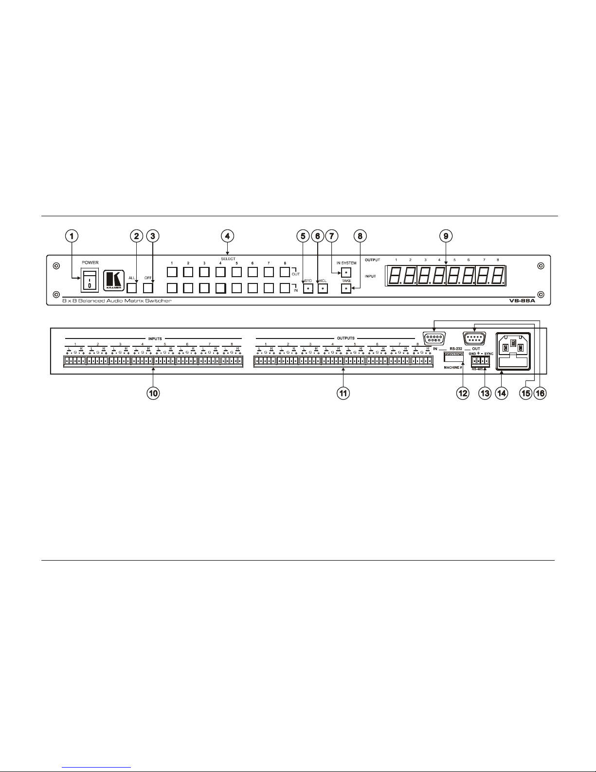
Figure 1: VS-88A 8x8 Balanced Audio Matrix Switcher
Your Matrix Switchers
5
Table 1: VS-88A 8x8 Balanced Audio Matrix Switcher Features
# Feature Function
1 POWER Switch Illuminated switch supplying power to the unit
2 ALL Button Pressing ALL before pressing an INP button, connects that input to all outputs1
3 OFF Button Pressing OFF after pressing an OUT button disconnects that output from the
inputs. To turn off the connections, press the ALL button and then the OFF
button
4 IN Select the output to which the input is switched (from 1 to 8)
SELECT
Buttons
OUT Select the input to switch to the output (from 1 to 8)
5 STO Button Pressing STO (Store) followed by an output button stores the current setting
(refer to section 8.2.1)2
6 RCL Button Pressing the RCL (Recall) button and the corresponding OUT key recalls a
setup. Press the RCL button again to implement the new status (refer to section
8.2.2)
7 IN SYSTEM Button Pressing IN SYSTEM twice3, switches between the Standalone mode (in which
the switcher implements any action independently from the others) and the In
System mode (in which all switchers implement the same action simultaneously)
8 TAKE Button
(TAKE = CONFIRM)
Pressing TAKE toggles the mode between the CONFIRM mode4 and the AT
ONCE mode (user confirmation per action is unnecessary)
9 OUTPUT labels Identifies a connection between the output and the input shown below it
INPUT Status Display Displays the selected input switched to the output (marked above each input)
10 INPUT Terminal Block
Connectors
Connect to balanced stereo audio sources (from 1 to 8)
11 OUTPUT Terminal
Block Connectors
Connect to balanced stereo audio acceptors (from 1 to 8)
12 MACHINE # Dipswitches setup (refer to section 6.1)
13 RS-485 Connector RS-485 detachable terminal block port. Pins # 1 to # 3 are for RS 485 and pin #
4 is for vertical sync distribution5 as Figure 7 illustrates
14 Power Connector with
Fuse
AC connector enabling power supply to the unit
15 RS-232 OUT 9-pin
D-sub Connector
Connects to the RS-232 IN 9-pin D-sub port of the next unit in the daisy-chain
connection6
16 RS-232 IN 9-pin
D-sub Connector
Connects to PC or Remote Controller7
1 For example, press ALL and then Input button # 2 to connect input # 2 to all the outputs
2 For example, press STO and then the Output button # 3 to store in Setup # 3
3 After pressing IN SYSTEM once, it blinks
4 When in Confirm mode, the TAKE button illuminates
5 The 88 Series RS-485 connector has 4 pins, and the remote controller RS-485 connector has just 3 pins
6 If the unit is the final unit in the daisy-chain connection, no termination is required
7 If the unit is not the first unit in the line, connects to the RS-232 OUT 9-PIN D SUB port of the previous unit in the line

KRAMER: SIMPLE CREATIVE TECHNOLOGY
Your Matrix Switchers
6
4.2 Your VS-88V 8x8 Video Matrix Switcher
The VS-88V is a high performance 8x8 composite video matrix switcher. In
addition, the VS-88V:
Is a true matrix switcher, enabling the user to simultaneously route any input to
any or all outputs
Supports more than 200MHz video bandwidth
Switches during the vertical interval1
Accepts analog video as the external source for its vertical interval trigger
Is controllable via the front panel buttons as well as the built-in RS-232 and
RS-485 interfaces
Includes 15 preset memory locations for quickly and easily accessing the most
frequently used configurations
May be used with the RC-8000, an optional remote controller (see section 0)
Functions as a standalone unit as well as part of a Kramer multi-signal switcher
system2
Can be combined as part of a group of VS-88V switchers that comprise a
component switcher3
Figure 2 and Table 2 define the VS-88V:
1 Transitions are glitch-free when sources share a common reference sync
2 Which includes digital and analog video, digital and analog audio, and RS-422 control switchers. When integrated into a
system, it can provide the rest of switchers with the vertical interval trigger
3 Refer to section 6.5 and Figure 9 on page 23
Your Matrix Switchers
7
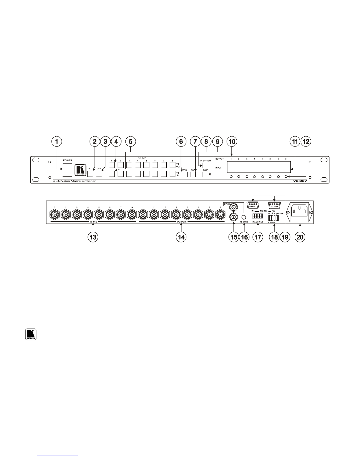
Figure 2: VS-88V 8x8 Video Matrix Switcher
KRAMER: SIMPLE CREATIVE TECHNOLOGY
Your Matrix Switchers
8
Table 2: VS-88V 8x8 Video Matrix Switcher Features
# Feature Function
1 POWER Switch Illuminated switch supplying power to the unit
2 ALL Button (ALL= All Outputs) Pressing ALL before pressing an INPUT button, connects that input to
all outputs1
3 OFF Button (OFF= All Inputs) Pressing OFF after pressing an OUTPUT button disconnects that output
from the inputs. To turn off the connections, press the ALL button and
then the OFF button
4 SELECT OUT Buttons Select the output to which the input is switched (from 1 to 8)
5 SELECT IN Buttons Select the input to switch to the output (from 1 to 8)
6 STO Button Pressing STO (STORE) followed by an output button stores the current
setting (refer to section 8.2.1)2
7 RCL Button Pressing the RCL (Recall) button and the corresponding OUT key
recalls a setup. Press the RCL button again to implement the new
status (refer to section 8.2.2)
8 IN SYSTEM Button Pressing IN SYSTEM twice3, switches between the Standalone mode
(in which the switcher implements any action independently from the
others) and the In System mode (in which all switchers implement the
same action simultaneously)
9 TAKE Button
(TAKE = CONFIRM)
Pressing TAKE toggles the mode between the CONFIRM mode4 and
the AT ONCE mode (user confirmation per action is unnecessary)
10 OUTPUT labels Identifies a connection between the output and the input shown below it
11 INPUT Status Display Displays the selected input switched to the output (marked above each
input)
12 Input Status LEDs Illuminate when the input signal is presented on a corresponding line
and complies with the SDI standard
13 INPUTS BNC Connectors Connect to the video sources (from 1 to 8)
14 OUTPUTS BNC Connectors Connect to the video outputs (from 1 to 8)
15 SYNC BNC Connectors For looping to external video sync input
16 75 ohms Button Controls loop termination5
17 RS-232 IN 9-pin D-sub
Connector
Connects to PC or Remote Controller6
18 MACHINE # Dipswitches For setup of the machine number (refer to section 6.1)
19 RS-485 Connector RS-485 detachable terminal block port. Pins # 1 to # 3 are for RS 485
and pin # 4 is for vertical sync distribution7
20 Power Connector with Fuse AC connector enabling power supply to the unit
9 RS-232 OUT 9-pin D-sub
Connector
Connects to the RS-232 IN 9-pin D-sub port of the next unit in the daisy-
chain connection 8
1 For example, press ALL and then Input button # 2 to connect input # 2 to all the outputs
2 For example, press STO and then the Output button # 3 to store in Setup # 3
3 After pressing IN SYSTEM once, it blinks
4 When in Confirm mode, the TAKE button illuminates
5 Push in to terminate the SYNC line. Push out when the line extends to another unit
6 If the unit is not the first unit in the line, connects to the RS-232 OUT 9-PIN D SUB port of the previous unit in the line
7 The 88 Series RS-485 connector has 4 pins, and the Remote Controller RS-485 connector has just 3 pins
8 If the unit is the final unit in the daisy-chain connection, no termination is required

Your Matrix Switchers
9
4.3 Your SD-7588A 8x8 Digital Audio Matrix Switcher
The SD-7588A is a high performance multi-standard 8x8 digital audio matrix
switcher that is adjustment-free, cable-equalized and reclocking. In addition,
the SD-7588A:
Provides automatic equalization for losses on 110 twisted pair cable
Reclocks each output to provide eight low-jitter digital outputs
Supports AES/EBU, IEC 958, S/PDIF and EIAJ CP340/1201 professional and
consumer formats with sampling frequencies up to 96kHz
Comes with all inputs and outputs transformer coupled, supporting 110
impedance twisted pair cable on detachable terminal block connectors
Is controllable via the front panel buttons as well as the built-in RS-232 and
RS-485 interfaces
Includes 15 preset memory locations for quickly and easily accessing the most
frequently used configurations
May be used with the RC-8000, an optional remote controller (see section 0)
Functions as a standalone unit as well as part of a Kramer multi-signal switcher
system1
Figure 3 and Table 3 define the SD-7588A:
1 Which includes digital and analog video, digital and analog audio and RS-422 control switchers. When integrated in a
system, it switches together with the video during the vertical interval, thus supporting true IN SYSTEM mode
 Loading...