

Page 1

Kramer Electronics, Ltd.
Preliminary
USER MANUAL
Models:
VS-44AV, 4x4 Video Audio Matrix Switcher
VS-81AV, 8x1 Video/Audio-Stereo Switcher
VS-81AYC, 8x1 s-Video/Audio-Stereo Switcher
VS-81V, 8x1 Video Switcher
VS-81X, 8x1 Balanced Audio Switcher
Page 2

Contents
i
Contents
1 Introduction 1
2 Getting Starte d 1
3 Kramer Mechanical Switchers 2
3.1 Your VS-44AV 4x4 Video Audio Matrix Switcher 2
3.2 Your VS-81AV 8x1 Video/Audio-Stereo Switcher 3
3.3 Your VS-81AYC 8x1 s-Video/Audio-Stereo Switcher 4
3.4 Your VS-81V 8x1 Video Switcher 5
3.5 Your VS-81X 8x1 Balanced Audio Switcher 7
4 Connecting Kramer Mechanical Switchers 8
4.1 Connecting a VS-81V 8x1 Video Switcher 8
4.2 Connecting a VS-81X Balanced Audio Switcher 9
4.3 Connecting a VS-81AV 8x1 Video/Audio-Stereo Switcher 10
Figures
Figure 1: VS-44AV 4x4 Video Audio Matrix Switcher 2
Figure 2: VS-81AV 8x1 Video/Audio-Stereo Switcher 3
Figure 3: VS-81AYC 8x1 s-Video/Audio-Stereo Switcher 5
Figure 4: VS-81V 8x1 Video Switcher 6
Figure 5: VS-81X 8x1 Balanced Audio Switcher 7
Figure 6: Connecting a VS-81V 8x1 Video Switcher 8
Figure 7: Connecting a VS-81X Balanced Audio Switcher 9
Figure 8: Connecting a VS-81A V 8x1 Video/Audio-Stereo Switcher 10
Tables
Table 1: VS-44AV Functions 2
Table 2: VS-44AV Technical Specifications 3
Table 3: VS-81AV Functions 4
Table 4: VS-81AV Technical Specifications 4
Table 5: VS-81AYC Functions 5
Table 6: VS-81AYC Tech nical Specifications 5
Table 7: VS-81V Functions 6
Table 8: VS-81V Technical Specifications 6
Table 9: VS-81X Functions 7
Table 10: VS-81X Technical Specification s 7
Page 3

Introduction
1
1 Introduction
Welcome to Kramer Electronics! Since 1981, Kramer Electronics has been
providing a world of unique, creative, and affordable solutions to the vast
range of problems that confront the video, audio, presentation, and
broadcasting professional on a daily basis. In recent years, we have
redesigned and upgraded most of our line, ma king the best even b etter! Our
1,000-plus different models now appear in 11 groups
1
Thank yo u for purchasing your Kramer mechanical switcher, which is ideal
for a system in which a passive, hard-wired signal path is preferred.
that are clearly
defined by function.
2 Getting Started
We recommend that you:
• Unpack t he equip ment carefully and s ave the original box and
packaging materials for possible future shipment
• Review the contents of this user manual
• Use Kramer high-performance high-resolution cables
2
Each package includes the following items:
• The one or more Kramer mechanical switchers
• This user manual
3
To achieve the best performance:
• Use only good quality connection cables to avoid interference,
deterioration in signal q uality due to poor matching, and elevated
noise levels (often associa te d with low quality cables).
• Avoid interference from neighboring electrical appliances that
may adversely influence signal quality and position your Kramer
switcher away from mois ture, excessive s unlight and dust
1 GROUP 1: Distribution Amplifiers; GROUP 2: Switchers and Matrix Switchers; GROUP 3: Control Systems;
GROUP 4: Format/Standards Converters; GROUP 5: Range Extenders and Repeaters; GR OUP 6: Specialty AV Products;
GROUP 7: Scan Converters and Scalers; GROUP 8: Cables and Connectors; GROUP 9: Room Connectivity;
GROUP 10: Accessories and Rack Adapters; GROUP 11: Sierra Products
2 The complete list of Kramer cables is on our Web site at
http://www.kramerelectronics.com
3 Download up-to-date Kramer user manuals from our Web site at http://www.kramerelectronics.com
Page 4
KRAMER: SIMPLE CREATIVE TECHNOLOGY
Kramer Mechanical Switchers
2
3 Kramer Mechanical Switchers
This user manual describes the following Kramer mechanical switchers:
• VS-44AV, 4x4 Video Audio Matrix (see section
3.1)
• VS-81AV, 8x1 Video/Audio-Stereo Switcher (see section
3.2)
• VS-81AYC, 8x1 s-Video/Audio-Stereo Switcher (see section
3.3)
• VS-81V, 8x1 Video Switcher (see section
3.4)
• VS-81X, 8x1 Balanced Audio Switcher (see section
3.5)
3.1 Your VS-44AV 4x4 Video Audio Matrix Switcher
The Kramer VS-44AV 4x4 Video Audio Matrix Switcher is a high-quality
mechanical 4x4 matrix switcher for composite video and stereo audio
signals. The VS-44AV is designed to simultaneously route up to 4 sources
each to any one of 4 available outputs. T he VS-44AV is unique in allowing
4 different cross points of video and stereo audio to operate at the same
time. However, it cannot simultaneously distribute an input signal to
multiple outputs. The high-quality input selector buttons are color coded for
easy identification a nd unselected inputs are terminated via 75Ω resistors.
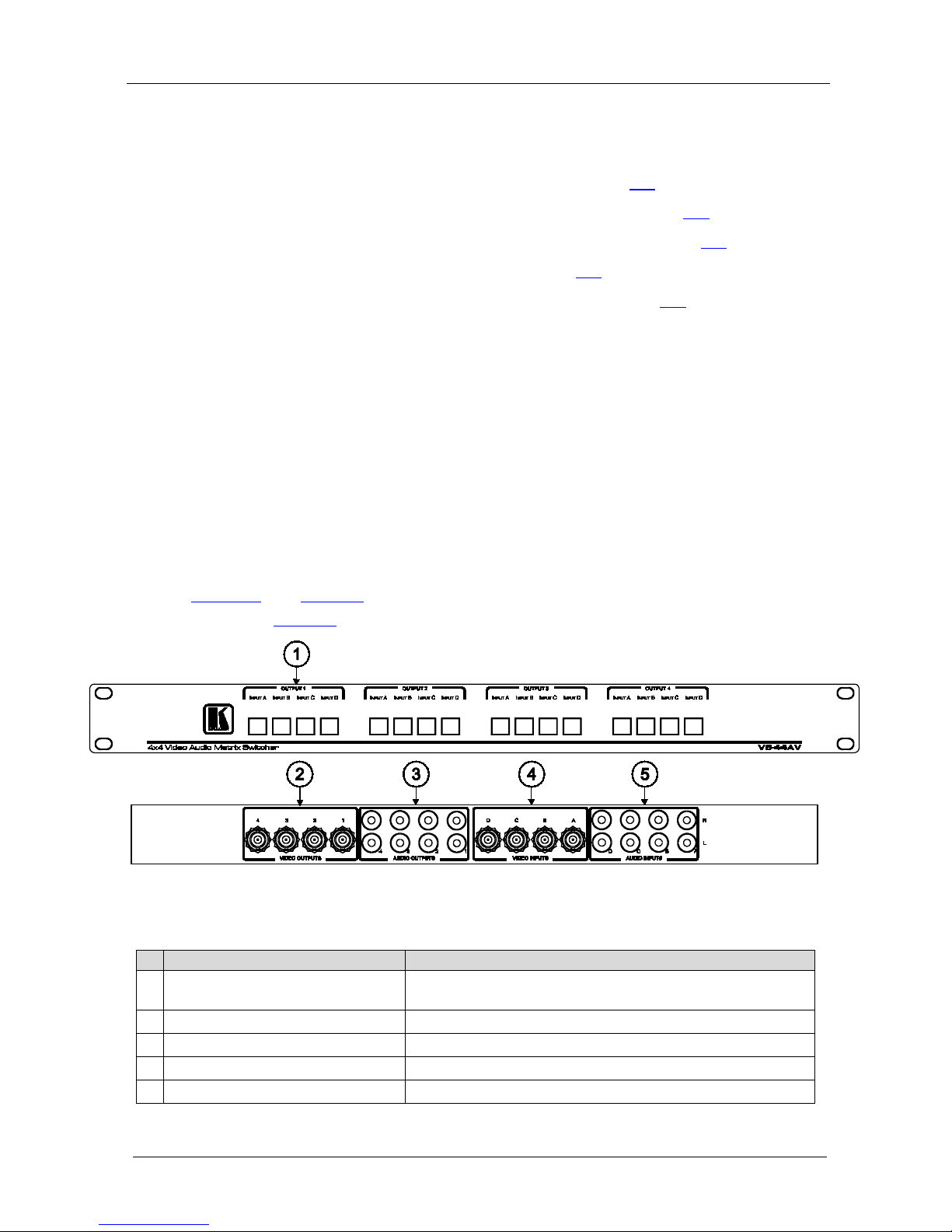
Figure 1 and Table 1 define the VS-44AV 4x4 Video Audio Matrix
Switcher.
Table 2 gives the technical specific a tions for the VS-44AV.
Figure 1: VS-44AV 4x4 Video Audio Matrix Switcher
Table 1: VS-44AV Functions
#
Feature
Function
1 OUTPUT/INPUT Selector Buttons Select the video and audio source (from A to D) to route to
each video/audio acceptor (from 1 to 4)
2
VIDEO OUTPUT BNC connectors Connect to the video acc eptors (from 1 to 4)
3
AUDIO OUTPUT RCA con nec tors Connect to the right and left audio acceptors (from 1 to 4)
4
VIDEO INPUT BNC con nectors Connect to the video sources (from A to D)
5
AUDIO INPUT RCA connectors Connect to the right and left audio sources (from A to D)
Page 5
Kramer Mechanical Switchers
3
Table 2: VS-44AV Technical Specifications
INPUTS:
4 video, 1Vpp/75Ω on BNC connectors
4 audio stereo, 1Vpp nominal on RCA connectors
OUTPUTS:
4 video, 1Vpp/75Ω on BNC connectors
4 audio stereo, 1Vpp nominal on RCA connectors
SWITCHING SYSTEM: Mechanical, break-before-make
CROSSPOINTS: 16 for video, 16x2 for audi o, 4 acti ve at an y give n tim e
CROSSTALK: -42dB @5MHz
BANDWIDTH (-3dB): 220MHz (video), 100kHz (audio )
SIGNAL LEVELS: Up to 3Vpp video, 36Vpp audio
DIMENSIONS: 19" x 7" x 1U W, D, H rack mountable
WEIGHT: 1.6kg (3.5lbs) approx.
3.2 Your VS-81AV 8x1 Video/Audio-St ereo Sw i tch er
The Kramer VS-81AV, 8x1 Video/Audio-Stereo Switcher is a high-quality
mechanical 8x1 switcher for composite video and stereo audio signals.
The VS-81AV is designed for applications requiring an unpowered rack-
mountable unit for routing of video and stereo audio signals. Audio is
always switched together with the corresponding video signal and
unselected video inputs are terminated via 75Ω resistors. High-quality
switching components p r ovide excellent isolation between inputs. Its
unpowered passive design is advantageous for applications in whi ch various
regulatory compliances would otherwise be required. The "hard-wired"
signal path offers excellent b andwidth, and can even switch other signal
formats.
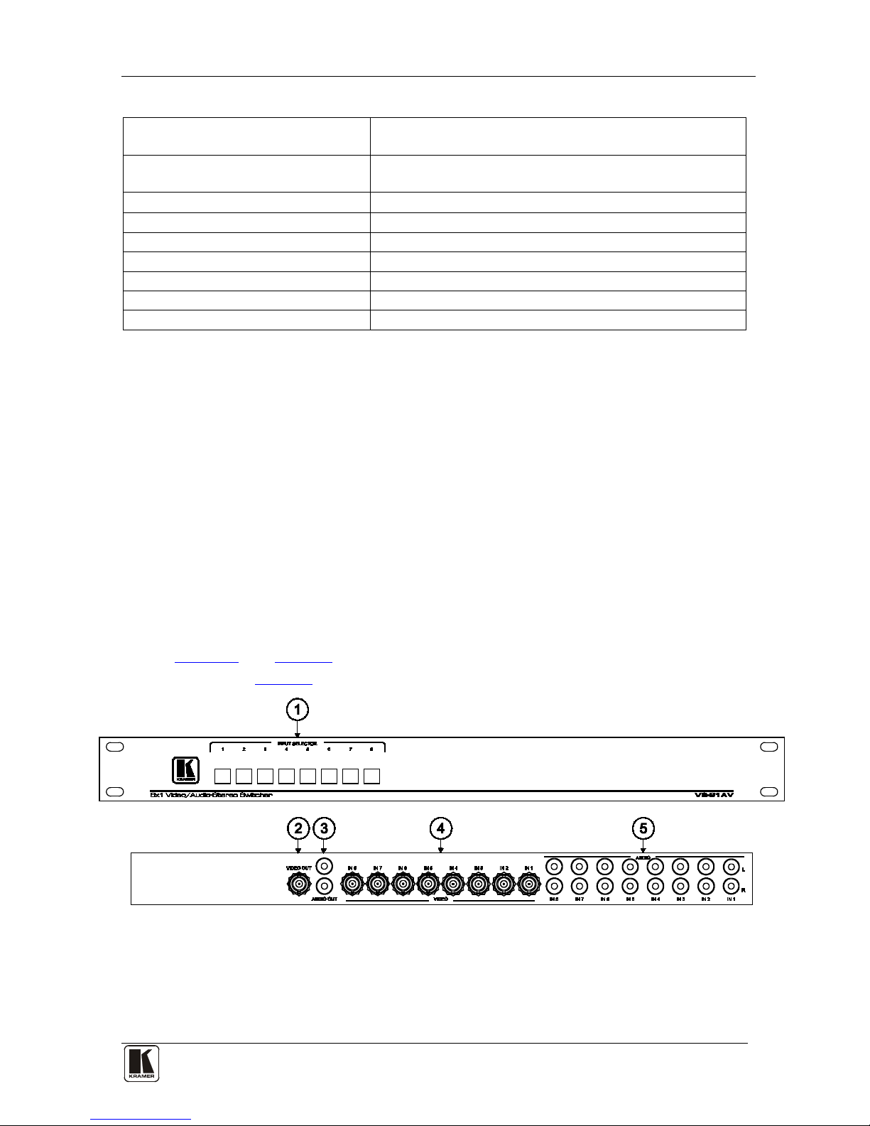
Figure 2 and Table 3 define the VS-81AV 8x1 Video/Audio-Stereo
Switcher.
Table 4 gives the technical specifica tions for the VS-81AV.
Figure 2: VS-81AV 8x1 Vide o/Audio-Stereo Switcher
Page 6

KRAMER: SIMPLE CREATIVE TECHNOLOGY
Kramer Mechanical Switchers
4
Table 3: VS-81AV Functions
#
Feature
Function
1 INPUT Selector Buttons Select the video/audio source (from 1 to 8) to route to the output
2
VIDEO OUT BNC connector Connects to the video acceptor
3
AUDIO OUT RCA connectors Connect to the left and right audio acceptor
4
VIDEO input BNC connectors Connect to the video sources (from 1 to 8)
5
AUDIO input RCA connectors Connect to the left and right audio sources (from 1 to 8)
Table 4: VS-81AV Technical Specifications
INPUTS:
8 video, 1Vpp/75Ω nom. on BNC connectors
8 audio stereo, 1Vpp nom. on RCA connectors
OUTPUT:
1 video, 1Vpp/75Ω nom. on a BNC connector
1 audio stereo, 1Vpp nom. on an RCA connector
SWITCHING SYSTEM: Mechanical, break-before-make
CROSSPOINTS: 1 of 8
SIGNAL LEVELS: Up to 3Vpp video, 36Vpp audio
BANDWIDTH (-3dB): Video: 400MHz; Audio: 100kHz
DIMENSIONS: 19" x 7" x 1U W, D, H rack mountable
WEIGHT: 1.5kg (3.3lbs) approx.
3.3 Your VS-81AYC 8x1 s-Video/Audio-Stereo Switcher
The Kramer VS-81AYC, 8x1 s-Video/Audio-Ste reo Switcher is a high
quality mechanical 8x1 switcher for s-Video (Y/C) and stereo audio
signals using 4-pin and RC A connectors. The VS-81AYC is designed for
applications requiring an unpowered rack mountable unit for the routing
of s-Video (Y/C) and stereo audio signals. Audio is always switched
together with the corresponding s-Video (Y/C) signal and unselected
video inputs are terminated via 75Ω resistors. H igh quality switching
components provide excellent isolation between inputs. Its unpowered
passive design is advantageous for applications in whic h various
regulatory compliances would otherwise be required. The "hard-wired"
signal path offers excellent b andwidth, and can switch other signal
formats.
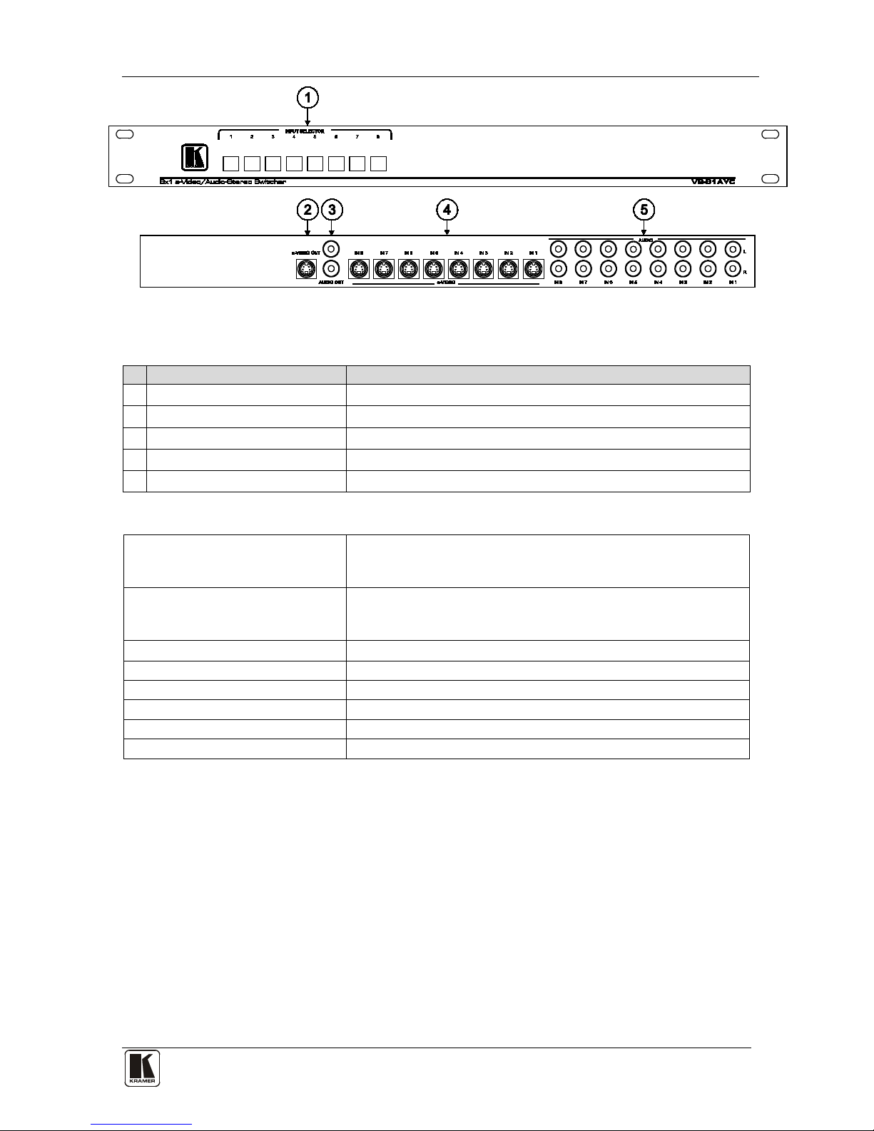
Figure 3 and Table 5 define the VS-81AYC, 8x1 s-Video/Audio-Stereo
Switcher.
Table 6 gives the technical specific a tions for the VS-81AYC.
Page 7
Kramer Mechanical Switchers
5
Figure 3: VS-81AYC 8x1 s-Video/Audio-Stereo Switcher
Table 5: VS-81AYC Fun c tions
#
Feature
Function
1 INPUT Selector Buttons Select the s-Video/audio source (from 1 to 8) to route to the output
2
s-VIDEO OUT 4-pin connector Connects to the s-VIDEO acceptor
3
AUDIO OUT RCA connect ors Connect to the left and right audio acceptor
4
s-VIDEO input 4-pin connector Connect to the s-VIDEO sources (from 1 to 8)
5
AUDIO input RCA connectors Connect to the left and right audio sources (from 1 to 8)
Table 6: VS-81AYC Technical Specifications
INPUTS:
8 s-Video, 1Vpp/75Ω (Y), 0.3 Vpp/75Ω (C) nom. on 4-pin
connectors
8 audio stereo, Vpp nom. on RCA connectors
OUTPUTS:
1 s-Video, 1Vpp/75Ω (Y), 0.3 Vpp/75Ω (C) nom on a 4-pin
connector
1 audio stereo, Vpp nom on RCA connectors
SWITCHING SYSTEM: Mechanical, break-before-make
CROSSPOINTS: 1 of 8
SIGNAL LEVELS: Up to 3Vpp video, 36Vpp audio
BANDWIDTH (-3dB): Video: 350MHz (Y); Audio: 100kHz
DIMENSIONS: 19" x 7" x 1U W, D, H rack mountable
WEIGHT: 1.4kg (3.1lbs) approx.
3.4 Your VS-81V 8x1 Video Switcher
The Kramer VS-81V, 8x1 Video Switcher is a high quality mechanical 8x1
switcher for composite video using BNC connectors. The VS-81V is
designed for applications requiring a compact desktop unit for routing
composite video signals. High qua lity switching component s and carefully
designed circuits provide excellent isolation between inputs and unselected
inputs are terminated via 75Ω resistors. Its unpowered design is
advantageous for applications in which various regulatory compliances
would otherwise be required. The passive "hard-wired" signal path offers
very high bandwidth and can also switch other signal formats.
Page 8
KRAMER: SIMPLE CREATIVE TECHNOLOGY
Kramer Mechanical Switchers
6
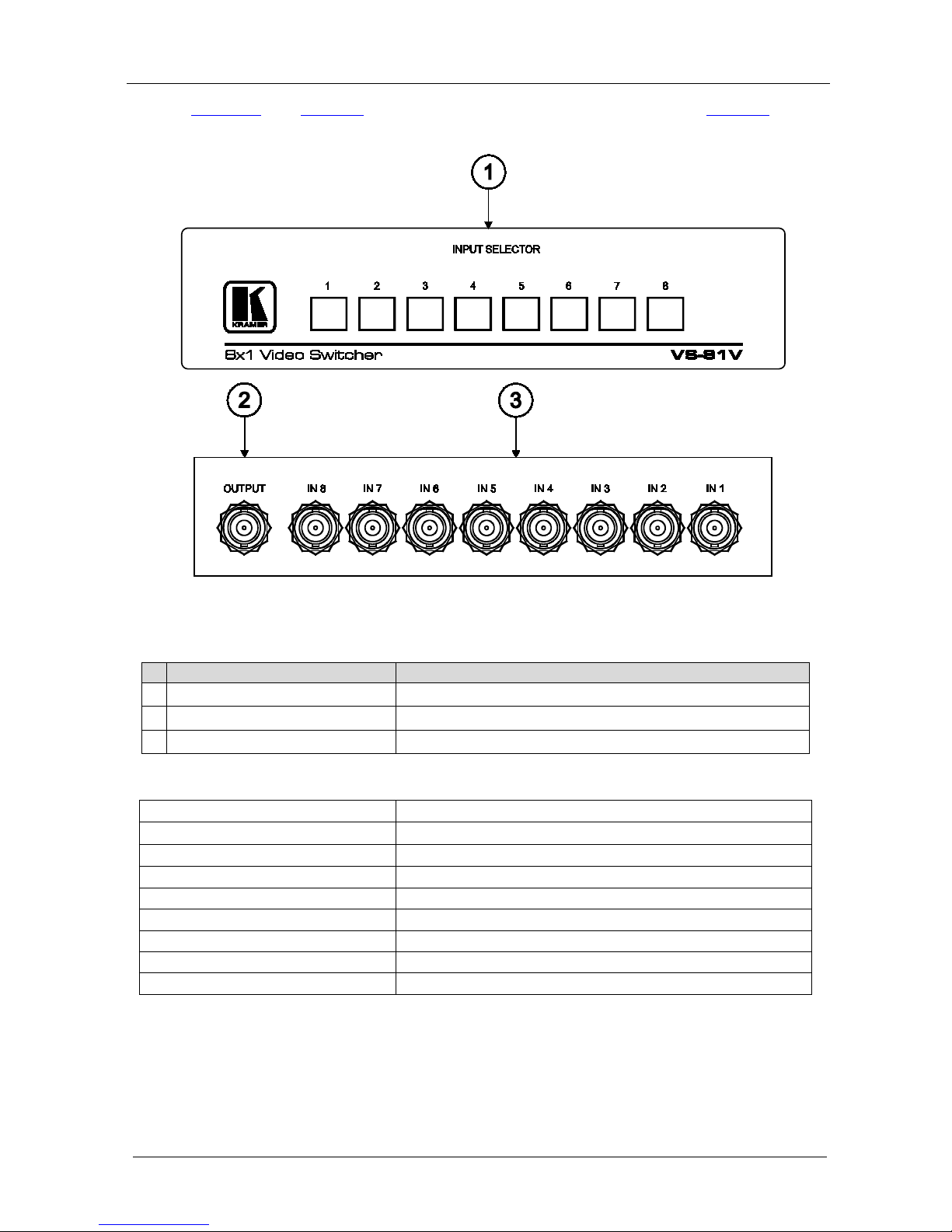
Figure 4 and Table 7 define the VS-81V, 8x1 Video Switcher. Table 8 gives
the technical specifica tions for the VS-81V.
Figure 4: VS-81V 8x1 Vide o Swi tcher
Table 7: VS-81V Functions
#
Feature
Function
1 INPUT Selector Buttons Select the video source (from 1 to 8) to route to the output
2
VIDEO OUTPUT BNC connector Connect to the video acceptor
3
VIDEO input BNC connectors Connect to the video sources (from 1 to 8)
Table 8: VS-81V Technical Specifications
INPUTS:
8 video, 1Vpp/75Ω nom. on BNC connectors
OUTPUTS:
1 video, 1 Vpp/75Ω nom. on a BNC connector
SWITCHING SYSTEM: Mechanical, break-before-make
CROSSPOINTS: 1 of 8
VIDEO CROSSTALK: -47dB @5MHz
BANDWIDTH (-3dB): 400 MHz
DIMENSIONS: 18.8cm x 10.2cm x 4.4cm (7.4" x 4" x 1.7") W, D, H.
WEIGHT: 0.72kg (1.6lbs) approx.
OPTIONS: RK-81 19" rack adapter
Page 9
Kramer Mechanical Switchers
7
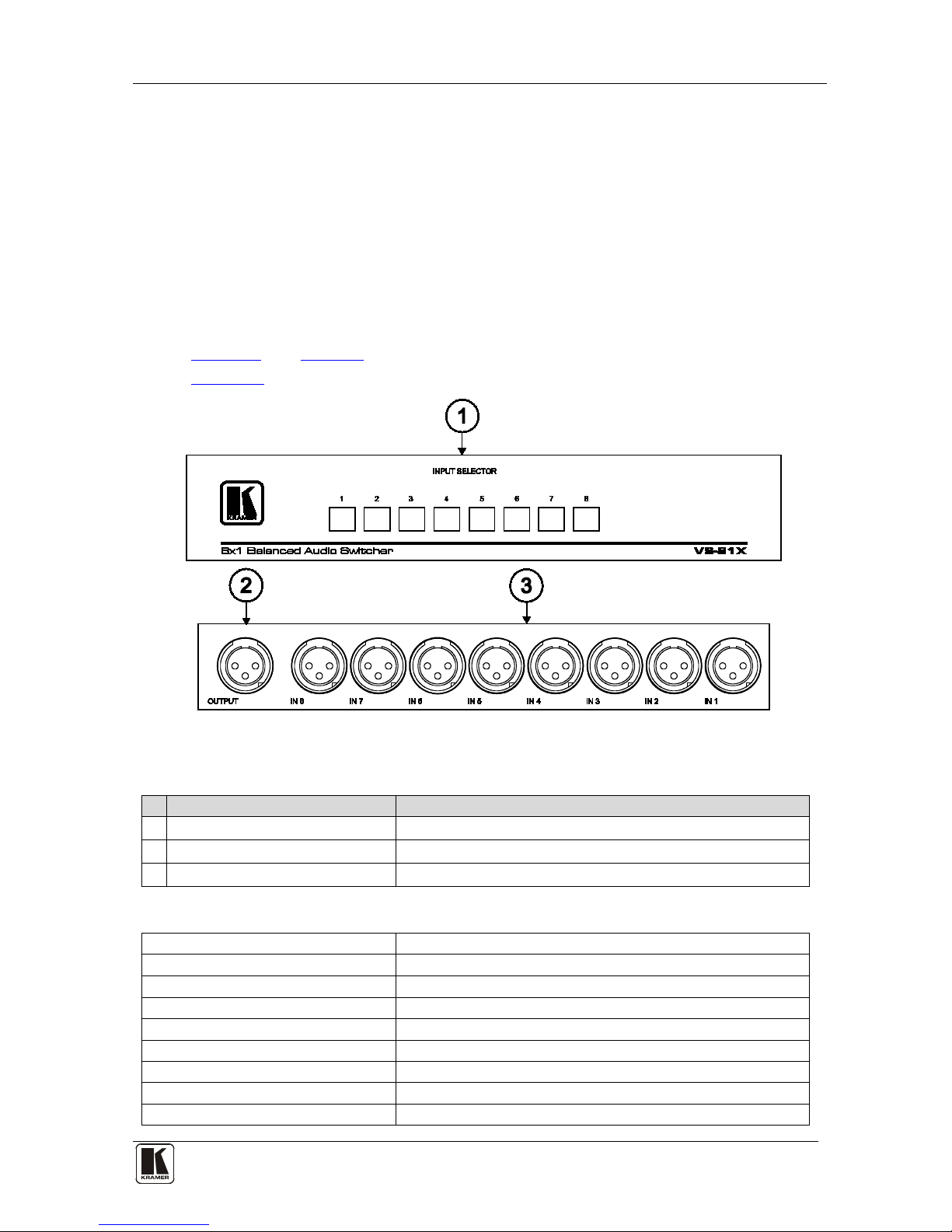
3.5 Your VS-81X 8x1 Balanced Audio Sw itch er
The Kramer VS-81X, 8x1 Balanced Audio Switcher is a high qua lity
mechanical 8x1 switcher for mono balanced audio using XLR connectors.
The VS-81X is designed for applications requiring a compact desktop unit
for routing audio signals. High quality switching components provide
excellent isolation between inputs. Its unpowered passive design is
advantageous for applications in which various regulatory compliances
would otherwise be required. The "hard-wired" signal path can also switch
other signal formats.
Figure 5
and Table 9 define the VS-81X, 8x1 Balanced Audio Switcher.
Table 10 gives the technical specification s for the VS-81X.
Figure 5: VS-81X 8x1 Bala nc e d A udi o Sw i tc he r
Table 9: VS-81X Functions
# Feature Function
1 INPUT Selector Buttons Select the audio source (from 1 to 8) to route to the output
2
AUDIO OUTPUT XLR connector Connect to the audio acceptor
3
AUDIO input XLR con nec tors Connect to the audio sources (from 1 to 8)
Table 10: VS-81X Techni c al Spe cifications
INPUTS: 8 balanced audio, line or mic level, on XLR connectors
OUTPUT: 1 balanced audio, line or mic level, on an XLR connector
SWITCHING SYSTEM: Mechanical, break-before-make
CROSSPOINTS: 1 of 8
SIGNAL LEVELS: Up to 36Vpp
BANDWIDTH (-3dB): 25kHz
DIMENSIONS: 25.5cm x 10.2cm x 4.5cm (10" x 4" x 1.7") W, D, H.
WEIGHT: 0.82kg (1.8lbs) approx.
OPTIONS: RK-81X 19" rack adapter
Page 10
KRAMER: SIMPLE CREATIVE TECHNOLOGY
Connecting Kramer Mechanical Switch er s
8
4 Connecting Kramer Mechanical Switchers
This section give s examples of how to connect Kramer mechanical
switchers.
• To connect a mechanical video switcher, see the example in section
4.1
• To connect a mechanical audio switcher, see the example in section
4.2
• To connect a mechanical audio/video switcher, see the example in
section
4.3
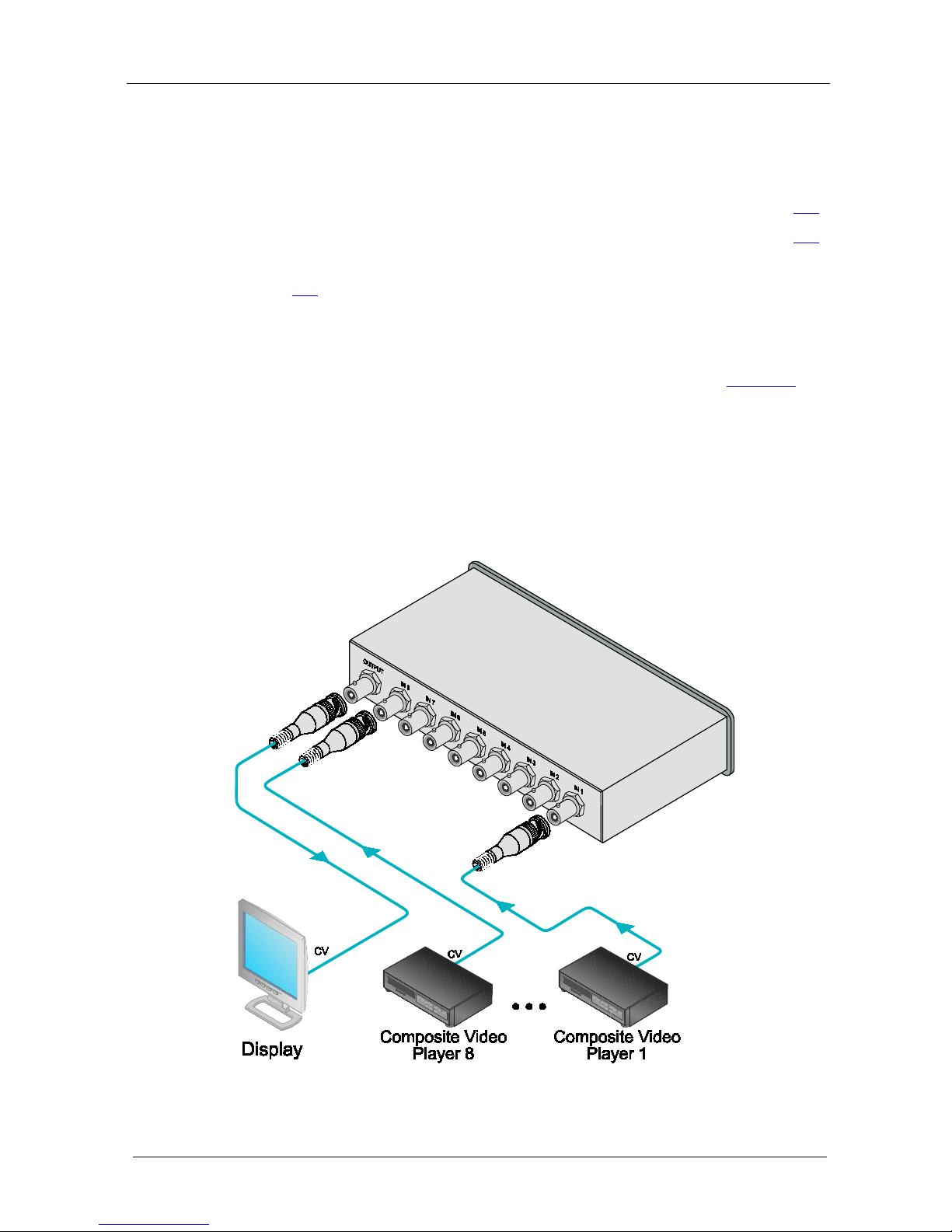
4.1 Connecting a VS-81V 8x1 Video Switcher
To connect your VS-81V 8x1 Video Switcher, as the example in
Figure 6
illustrates:
1. Connect up to 8 compos it e vi de o sources to the appropriate BNC input
connectors.
2. Connect the BNC OUTPUT connector to the compos i te vi d eo acceptor.
Pushing a front panel INPUT selector button routes that composite video
source to the composite video acceptor.
Figure 6: Connecting a VS-81V 8x1 Video Switcher
Page 11
Connecting Kramer Mechanical Switch er s
9
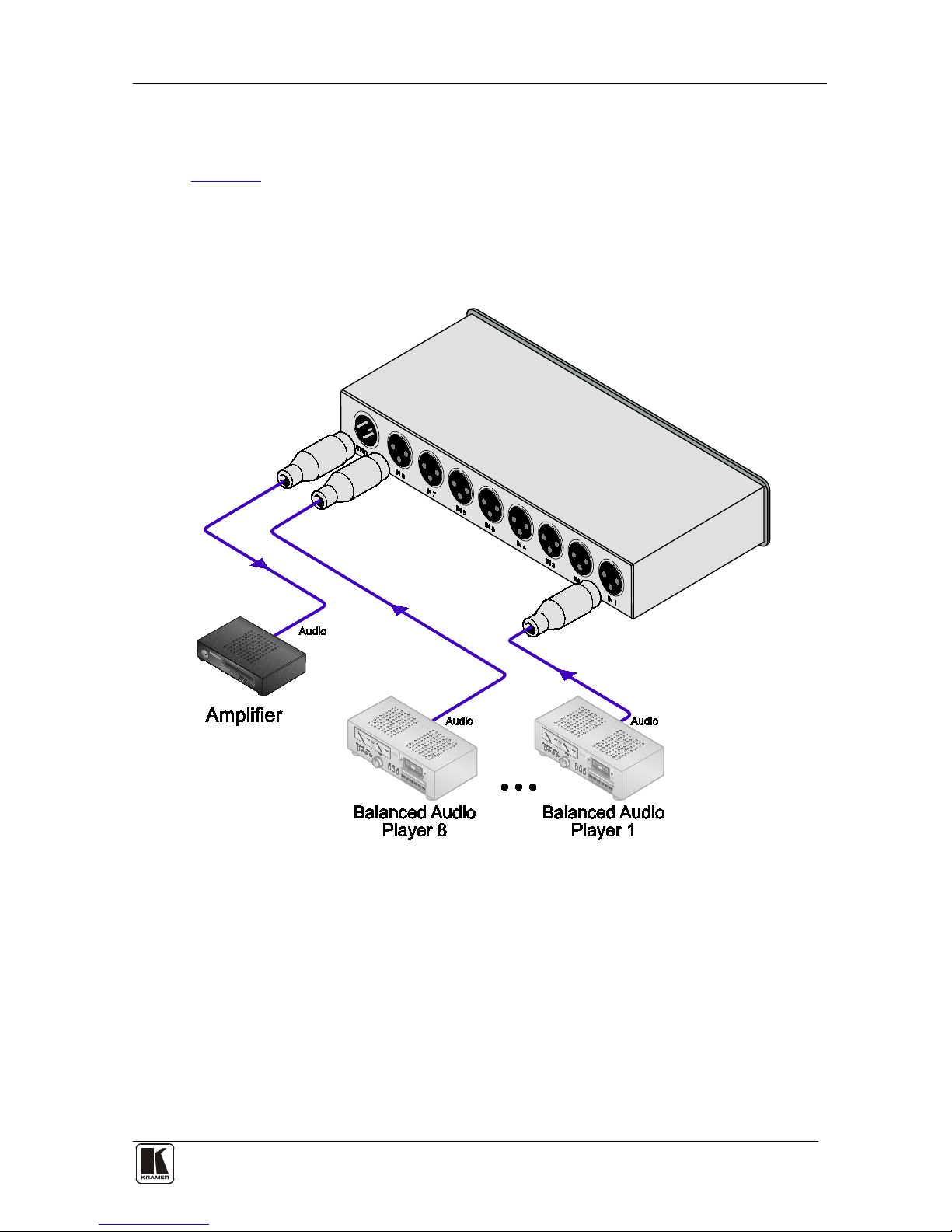
4.2 Connectin g a VS-81X Balanced Audio Sw i tch er
To connect your VS-81X Balanced Audio Switcher, as the example in
Figure 7 illustrates:
1. Connect up to 8 balanced audio sources to the 8 XLR i npu t con nect ors.
2. Connect the XLR OUTPUT connector to the audio acceptor.
Pushing a front panel INPUT selector button routes that balanced audio
source to th e bal ance d au di o a ccep tor .
Figure 7: Connecting a VS-81X Balanced Audio Switcher
Page 12
KRAMER: SIMPLE CREATIVE TECHNOLOGY
Connecting Kramer Mechanical Switch er s
10
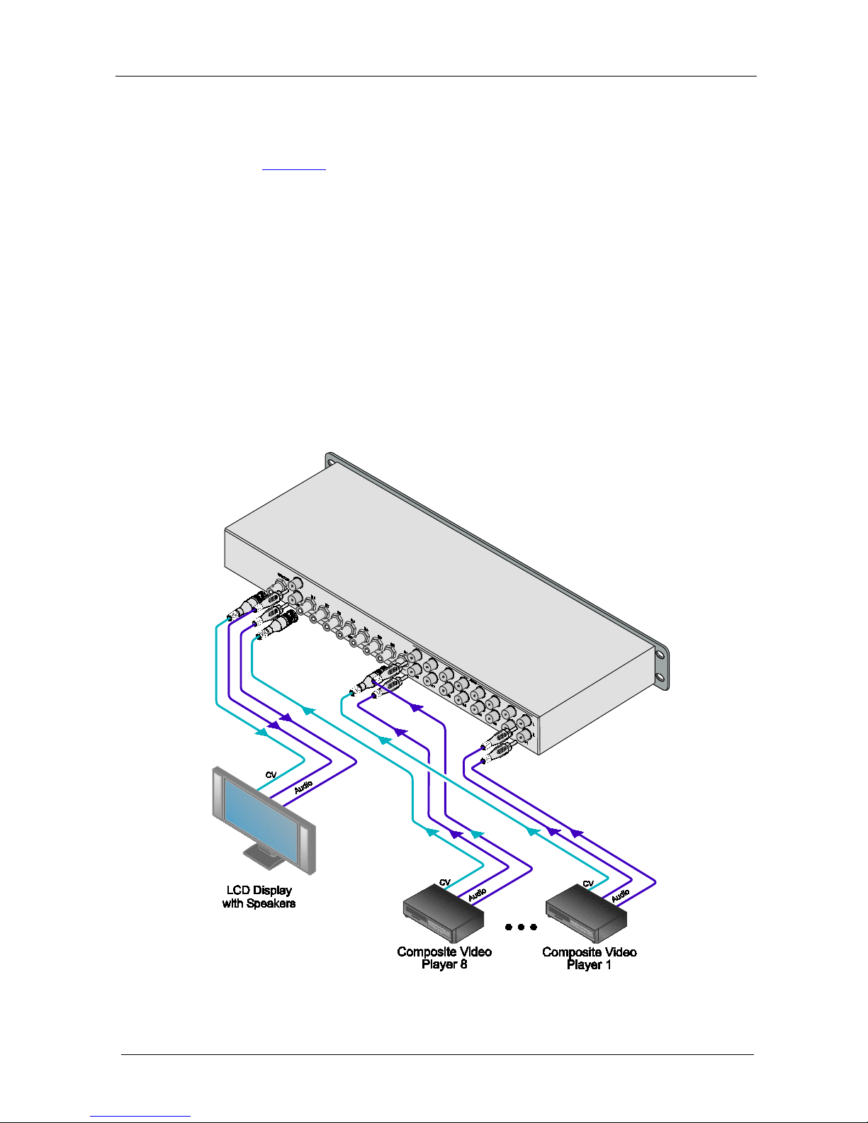
4.3 Connectin g a VS-81AV 8x1 Video/Audio-Stereo Switcher
To connect your VS-81AV
8x1 Video/Audio-Stereo Switcher, as the
example in
Figure 8 illustrates:
1. Connect up to 8 composite video sources to the VIDEO IN BNC
connectors.
2. Connect up to 8 audio sources to the AUDIO IN RCA connectors making
sure that the audio and video inputs match (that is, from Player 1, connect
the vi deo t o VI DEO IN 1 and the audio to AUDIO IN 1, and so on.)
3. Connect the VIDEO OUT BNC connector to the video acceptor (for
exam ple , a c om pos i t e v id e o display).
4. Connect the AUDIO OUT RCA connectors to the audio acceptor (for
exam ple , a c om pos i t e v id e o display with speakers).
Pushing a front panel INPUT selector button routes the selected AV source
to the A V acc ept or.
Figure 8: Connecting a VS-81AV 8x1 Video/Audio-Stereo Switcher
Page 13

11
11
LIMITED WARRANTY
WHO IS PROTECTED?
WHA T IS COVERED AND WHA T IS NOT COVERE D
WHA T WE WILL P A Y FOR A ND WHA T W E WILL NOT P A Y FOR
HOW YOU CAN GET WARRANTY SERVICE
LIMITA TION OF IMPLIED WARRANTIES
EXCLUSION OF DAMAGES
CAUTION!
Kramer Electronics (hereafter ) warrants this product free from defects in material and workma ns hip unde r the
following terms.
Kramer
HOW LONG IS THE W ARRANTY
Labor and parts are warranted for seven years from the date of the first customer purchase.
Only the first purchase customer may enforce this warranty.
W e will p ay labor and ma teria l expen ses for cover ed item s. W e wi ll not pa y for th e fol lowing:
The li abil ity of Krame r for any e ffe ct ive pr oduc ts is l imi ted t o the repair or re pla ceme nt of the pro duc t at ou r opt ion. Kram er sha ll
not be liabl e for:
This wa rran ty give s you spec ific l egal rights , and yo u may al so have other r ights, w hich va ry fr om place to place.
All produ cts ret urned t o Krame r for service must hav e pri or approv al. This ma y be obt ained f rom you r deal er.
This e quipm ent has b een tes ted to determi ne co mpliance with t he requ ireme nts of:
EN-50 081: "Elec troma gnetic c ompat ibility (EMC) ;
generic emission standard.
Reside ntia l, comm ercial a nd lig ht indus try"
EN-50 082: "Elec troma gnetic c ompat ibility (EMC) generi c immuni ty st andar d.
Part 1 : Reside ntia l, comm ercial and lig ht indus try e nviro nment".
CFR-47: FCC* Rules and Regulations:
Part 15 : “Ra d io frequency devices
Subpart B Unintentional radiators”
Except as below, this warranty covers all defects in material or workmanship in this product. The following are not covered
by the warranty:
1. Any product which is not distributed by Kramer, or which is not purchased from an authorized Kramer dealer. If you are
uncertain as to whether a dealer is authorized, please contact Kramer at one of the agents listed in the Web site
www.kramerelectronics.com.
2. Any product, on which the serial number has been defaced, modified or removed, or on which the WARRANTY VOID
TAMPERED sticke r ha s be en torn,
3. Damage, deterio ratio n or ma lfuncti on resu lting from:
i) Accident, misuse, abuse, neglect, fire, water, l ightn ing or oth er ac ts of nat ure
ii) Produc t modi ficati on, or fa ilur e to foll ow instr ucti ons sup plied w ith the produ ct
iii) Rep air o r atte mpted re pair by a nyone not au thoriz ed by Kra mer
iv) Any ship ment o f the pr oduct (claim s must b e pres ented to the carr ier)
v) Remova l or i nstalla tion of the pro duct
vi) Any other cause, which does not relate to a product defect
vii)Cartons, e quipm ent encl osure s, cabl es or accesso ries use d in c onjunc tion wi th the p roduct
1. Rem oval or insta llatio ns char ges.
2. Costs of initial technical adjustments (set-up), including adjustment of user controls or programming. These costs are the
respon sibi lity of the Kram er deal er fr om whom t he produ ct wa s purcha sed.
3. Shipp ing char ges .
1. To obtain service on you product, you must take or ship it prepaid to any authorized Kramer service center.
2. Whenever warranty service is required, the original dated invoice (or a copy) must be presented as proof of warranty
coverage, and should be included in any shipment of the product. Please also include in any mailing a contact name,
company, address, and a description of the problem(s).
3. For the name of the nearest Kramer authorized service center, consult your authorized dealer.
All implied warranties, including warranties of merchantability and fitness for a particular purpose, are limited in duration to
the length of this warranty.
1. Damag e to other prop erty cau sed by def ects in this product , damage s based upon inc onven ience , loss of use of the produ ct, los s
of time, commercial lo ss; o r:
2. Any ot her dam ages , w het her i nci den tal, conse que nti al o r o the rwise . S ome c oun tri es ma y n ot a llow lim ita tion s on ho w lon g a n
implied warranty lasts and/or do not allow the exclusion or limitation of incidental or consequential damages, so the above
limit ation s and exc lusio ns may no t apply to yo u.
Servicing the machines can only be done by an authorized Kramer technician. Any user who makes changes or
modifications to the unit without the expressed approval of the manufacturer will void user authority to operate the
equipment.
Use th e suppl ied DC p ower sup ply t o feed p ower to t he mach ine.
Please use recommended interconnection cables to connect the machine to other components.
IF reattached, removed or otherwise interfered with.
* FCC and CE appro ved usin g STP cable ( for twist ed pai r produc ts)
NOTE:
Part 1 :
Page 14

Kramer Electronics, Ltd.
Web site: www.kramerelectronics.com
E-mail: [email protected]
P/N: 2900-000638 REV 1
For the latest information on our products and a list of Kramer
distributors, visit our Web site:
www.kramerelectronics.com
where updates to this user manual may be found.
We welcome your questions, commen ts and feedba ck .
Caution
Safety Warning:
Disconnect the unit from the power supply before
opening/servicing.
 Loading...