

Kramer VS-81SP User Manual

Kramer Electronics, Ltd.
USER MANUAL
Model:
VS-81SP
8 x 1 Loudspeaker Switcher

Contents
i
Contents
1 Introduction 1
2 Getting Started 1
2.1 Quick Start 2
3 Overview 3
4 Your VS-81SP 8 x 1 Loudspeaker Switcher 3
5 Installing the VS-81SP in a Rack 6
6 Connecting the VS-81SP 8 x 1 Loudspeaker Switcher 7
6.1 Connecting via RS-232 9
6.2 Connecting via RS-485 9
6.3 DIP-switch Settings 10
6.3.1 Setting the MACHINE # 11
6.3.2 Setting the MACHINE ADDRESS # 13
6.4 Connecting the REMOTE Terminal Block Connector 15
7 Operating the VS-81SP 8 x 1 Loudspeaker Switcher 17
7.1 Using the Front Panel Buttons 17
7.2 Using Serial Commands 17
7.3 Operating via the Infrared Remote C ont ro ll er 17
8 Technical Specifications 18
9 Upgrading the VS-81SP Firmware 18
9.1 Downloading from the Internet 18
9.2 Connecting a PC to the RS-23 2 P or t 19
9.3 Installing the Firmware 19
10 Hex Table 25
11 Kramer Protocol 2000 25

KRAMER: SIMPLE CREATIVE TECHNOLOGY
Contents
ii
Figures
Figure 1: VS-81SP 8 x 1 Loudspeaker Switcher Functions 4
Figure 2: Connecting the VS-81SP – 1 Amplifier to 8 Speaker Pairs 8
Figure 3: Connecting the VS-81SP – 8 Amplifiers to 1 Speaker Pair
8
Figure 4: Connecting a PC Without Using a Null-modem Adapter
9
Figure 5: Controlling via RS-485
10
Figure 6: SETUP DIP-switches (Factory Default for Stand-Alone MACHINE # 1) 10
Figure 7: DIP-switch Settings on 4 VP-81SP Units
12
Figure 8: Casc a ding 3 VP-81SP Units
14
Figure 9: Addressing 3 Cascaded VP-81SP Units
14
Figure 10: Connecting a Remote Mechanical Switcher Uni t to the VP-81SP 15
Figure 11: Connecting a Remote Unit to a Cascaded Set of Three VP-81SP Units
16
Figure 12: Splash Screen
20
Figure 13: Atmel – Flip Window
20
Figure 14: Device Selection Window
21
Figure 15: Device Selection Window 21
Figure 16: Loading the Hex
22
Figure 1 7: RS-232 Window
22
Figure 18: Atmel – Flip Window (Connected)
23
Figure 19: Atmel – Flip Window (Operation Completed) 24
Tables
Table 1: VS-81SP 8 x 1 Loudspeaker Switcher Functions 5
Table 2: DIP-switch Definitions
11
Table 3: MACHINE # DIP-switch Settings
11
Table 4: MACHINE ADDRESS # DIP-switch Settings 13
Table 5: VS-81SP Technical Specificat ions
18
Table 6: VS-81SP Hex Table
25
Table 7: Protocol Definitions
25
Table 8: Instruction Codes for Protocol 2000 26

Introduction
1 1
1 Introduction
Welcome to Kramer Electronics! Since 1981, Kramer Electronics has been
providing a world of unique, creative, and affordable solutions to the vast
range of problems that confront the video, audio, presentation, and
broadcasting professional on a daily basis. In recent years, we have
redesigned and upgraded most of our line, ma king the best even b etter! Our
1,000-plus different models now appear in 11 groups
1
Thank yo u for purchasing the Kramer VS-81SP 8 x 1 Loudspeaker
Switcher, which is ideal for :
that are clearly
defined by function.
• Hi-fi retail stores
• Public address systems
• Home entertainment
Each package includes the following items:
• The VS-81SP 8 x 1 Loudspeaker Switcher
• Null-modem adapter, a power cord
2
• Windows®-based Kramer control software
and an infrared remote
control transmitter (including the required battery and a separate
user manual )
• This user manual
3
2 Getting Started
We recommend that you:
• Unpack the equipme nt carefully and save the original box and
packaging materials for possible future shipment
• Review the c ontent s of this user manual
• Use Kramer high-performance high-resolution cables
4
1 GROUP 1: Distribution Amplifiers; GROUP 2: Switchers and Matrix Switchers; GROUP 3: Control Syste ms; GROUP 4:
Format/Standards Converters; GROUP 5: Range Extenders and Repeaters; GROUP 6: Specialty AV Products; GROUP 7:
Scan Converters and Scalers; GROUP 8: Cables and Connectors; GROUP 9: Roo m Connectivity; GROUP 10: Accessories
and Rack Adapters; GROUP 11: Sierra Products
2 We recommend that you use only the power cord supplied with this device
3 Download up-to-date Kramer user manuals from our Web site at
http://www.kramerelectronics.com
4 The complete list of Kramer cables is on our Web site at
http://www.kramerelectronics.com
KRAMER: SIMPLE CREATIVE TECHNOLOGY
Getting Started
2
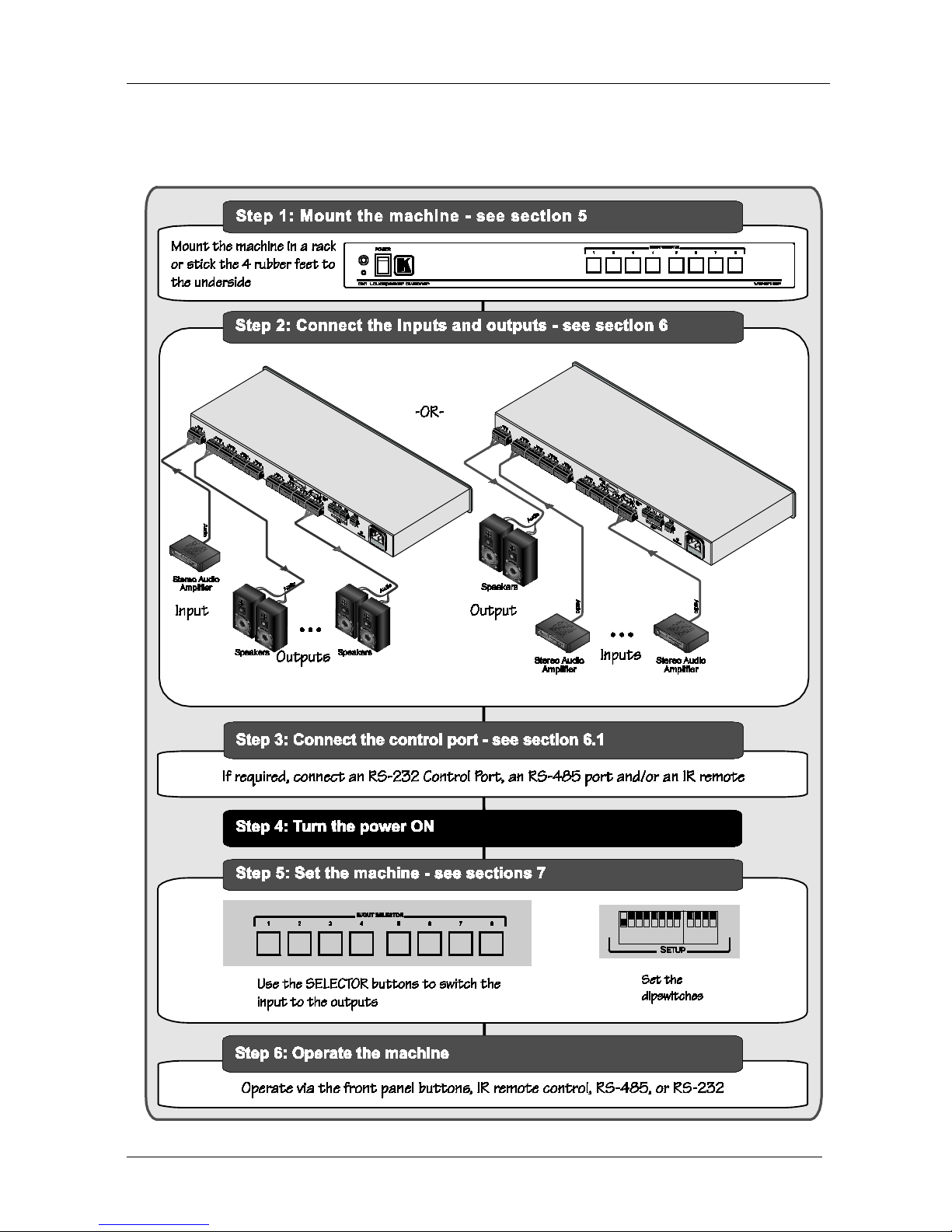
2.1 Quick Start
This quick start chart summarizes the basic setup and operation steps.

Overview
3 3
3 Overview
The VS-81SP is a bi-directional switcher for stereo audio speaker signals on
terminal block connectors. It can switch any one of eight pairs of input
signals to one output pair or one input pair to any one of eight output pairs.
The VS-81SP has the following features:
• 8 x 1 input/output stereo connections wit h bi-directional
functionality
• The ability to cascade up to seven units to increase the number of
inputs or outputs
• The ability to handle both high-impedance (100/70V) and
low-impedance (8/4Ω) signals
• Control from the front panel, or via RS-232/RS-485 serial
commands transmitted by a touch screen system, PC, or other
serial control device, as well as via an infrared remote controller,
or via remote contact-closure switches
To achieve the best performance:
• Use only good quality connection cables
1
• Avoid interference from neighboring electrical appliances that
may adversely influence signal quality and position your Kramer
VS-81SP away from moisture, excessive sunlight and dust
to avoid interference,
deterioration in signal q uality due to poor matching, and elevated
noise levels (often associa te d with low quality cables).
Caution – No operator-serviceable parts inside unit.
Warning – Use only the Kramer Electronics input power
wall adapter that is provide d with this unit
2
.
Warning – Di sconnect po wer and unplug unit from wall
before i ns talling or removing device or ser vicing unit.
4 Your VS-81SP 8 x 1 Loudspeaker Switcher
Figure 1 and Table 1 define the unit.
1 Available from Kramer Electronics on our Web site at http://www.kramerelectronics.com
2 For example, part number 2535-000251
KRAMER: SIMPLE CREATIVE TECHNOLOGY
Your VS-81SP 8 x 1 Loudspeaker Switcher
4
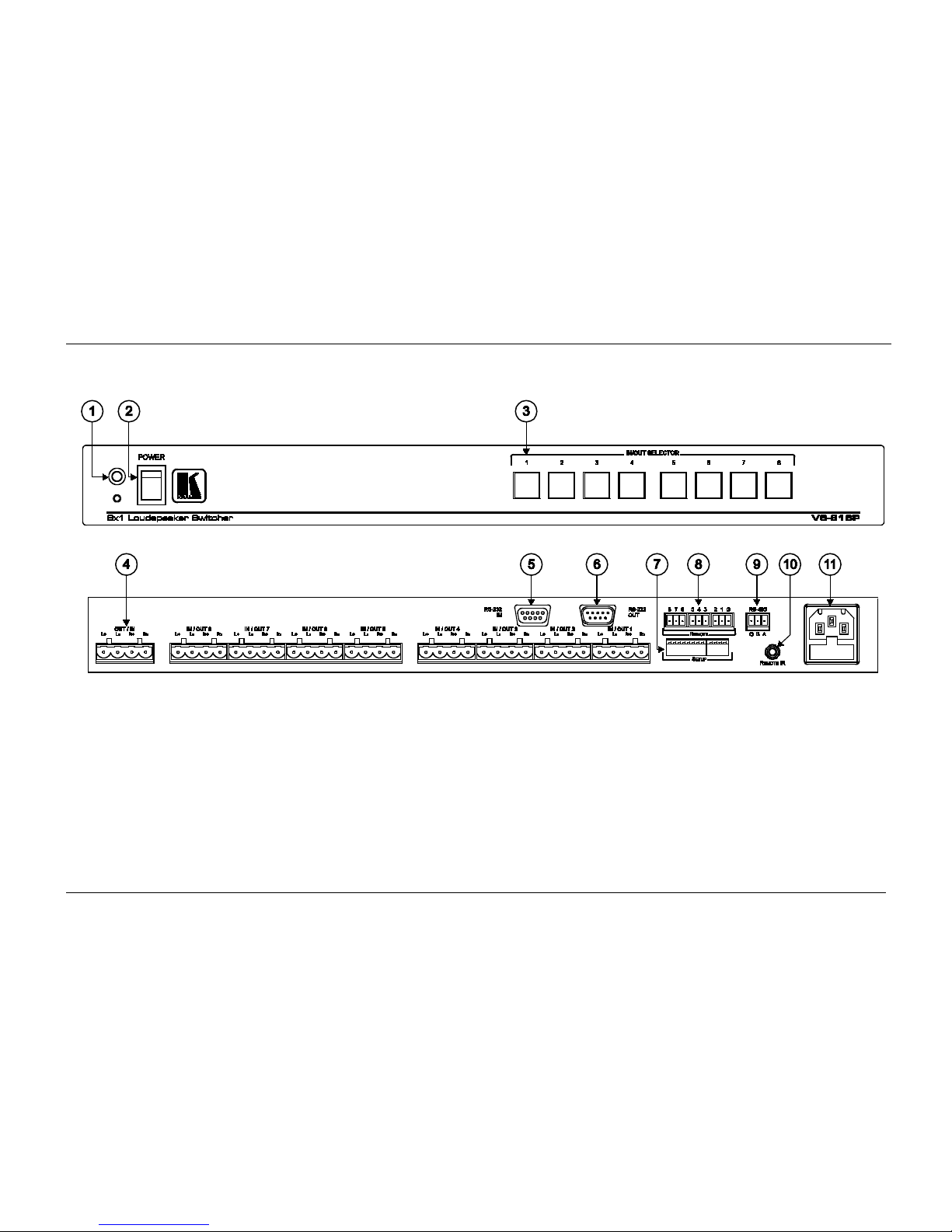
Figure 1: VS-81SP 8 x 1 Loudspeaker Switcher Functions
Your VS-81SP 8 x 1 Loudspeaker Switcher
5 5
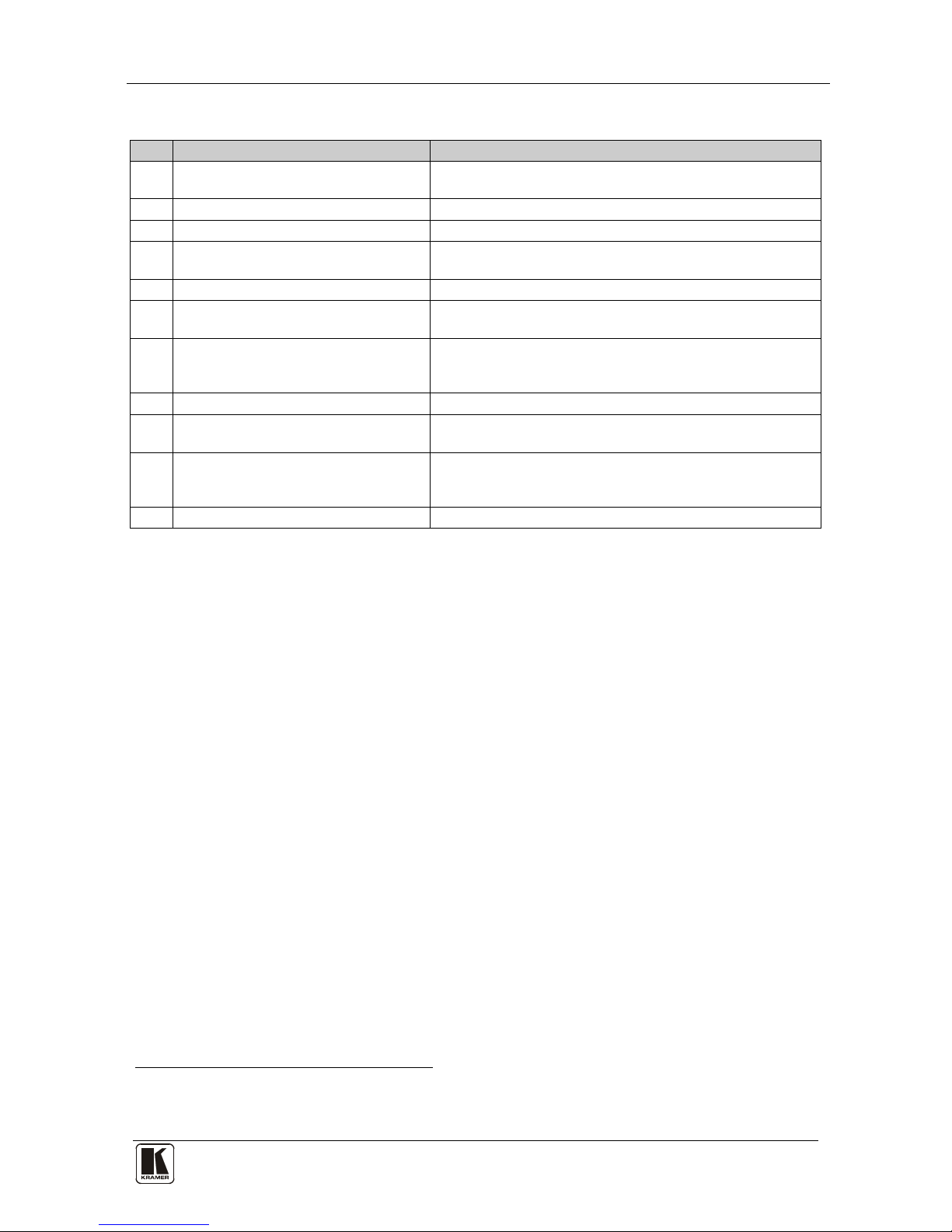
Table 1: VS-81SP 8 x 1 Loudspeaker Switcher Functions
#
Feature
Function
1 IR Receiver The red LED illuminates when receiving signals from the
infrared remote control transmitter
2 POWER Switch Illuminated switch for turning the unit ON and OFF
3 IN/OUT SELECTOR Buttons Select which output (from 1 to 8) to switch from the input
4 OUT/IN Terminal Block Connectors Connects to the input source(s) and the output speaker
pair(s) (from 1 to 8)
5 RS-232 IN 9-pin D-sub (F) Port Connects to the PC or RS-232 remote controller
6 RS-232 OUT 9-pin D-sub (M) Port Con nects to the RS-232 IN 9-pin D-sub (F) port of the next
unit in the daisy-chain
7 SETUP DIP-switches DIP-switches fo r setting up the unit (1 to 8 are for setting
addresses, 9 to 11 for software download, and 12 is for
RS-485 termination)
8 REMOTE Terminal Block Connectors Connect to the remote contact-closure switches
9 RS-485 Terminal Block Port Pins B (-) and A (+) are for RS-485, pin G may be conne cte d
to the shield (if required)
10 REMOTE IR Opening C onnects to an ex ternal IR receiv er unit for contr olling the
machine via an IR remote controller (instead of using the front
panel IR recei ver)
1
11 Power Connecto r wit h Fus e AC connector enabling power supply to the unit
1 Optional. Can be used instead of the front panel (built-in) IR receiver to remotely control t he machine (only if the in ternal
IR connection cable has been installed)
KRAMER: SIMPLE CREATIVE TECHNOLOGY
Installing the VS-81SP in a Rack
6
5 Installing the VS-81SP in a Rack
This section descr ibes how to install the VS-81SP in a rack.
Before Installing in a rack
How to Rack Mount
Before installing in a rack, be sure that the environment is
within the recommended range:
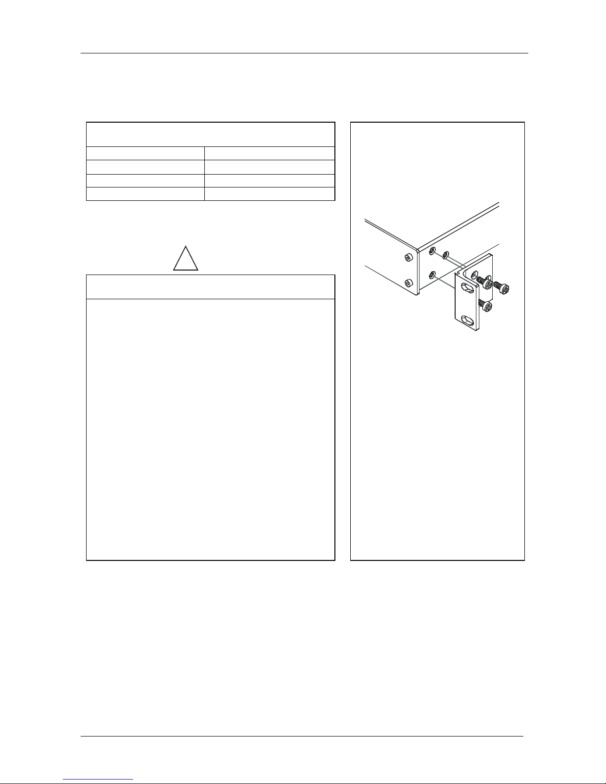
To rack-mount a machine:
1. Attach both ear brackets to the
machine. To do so, remove the
screws from each side of the
machine (3 on each side), and
replace those screws through the
ear brackets.
2. Place the ears of the machine
against the rack rails, and insert the
proper screws (not provided)
through each of the four holes in the
rack ears.
Note that:
• In some models, the front panel
may feature built-in rack ears
• Detachable rack ears can be
removed for desktop use
• Always mount the machine in the
rack before you attach any cables
or connect the machine to the
power
• If you are using a Kramer rack
adapter kit (for a machine that is not
19"), see the Rack Adapters user
manual for installation instructions
(you can download it at:
http://www.kramerelectronics.com)
Operating temperature range +5º to +45º C (41º to 113º F)
Operating humidity range 10 to 90% RHL, non-condensing
Storage temperature range -20º to +70º C (-4º to 158º F)
Storage humidity range 5 to 95% RHL, non-condensing
!
CAUTION!!
When installing on a 19" rack, avoid hazards by taking
care that:
1. It is located within the recommended environmental
conditions, as the op era ti ng ambi ent t e m pera tur e of a
closed or multi unit rack assembly may exceed the
room ambient temperature.
2. Once rack mounted, enough air will still flow around
the machine.
3. The machine is placed straight in the correct
horizontal positi on.
4. You do not overload the circuit(s). When connecting
the machine to the supply circuit, overloading the
circuits might have a detrimental effect on overcurrent
protection and supply wiring. Refer to t he app ro priate
nameplate ratings for information. For example, for
fuse replacemen t, s ee the value printed on the
product label.
5. The machine is earthed (grounded) in a reliable way
and is connected onl y to an ele ctric ity socket with
grounding. Pay particular attention to situations where
electricity is supplied indirectly (when the power cord
is not plugged directly into the socket in the wall), for
example, when using an extension cable or a power
strip, and that you use only the power cord that is
supplied with the machine.

Connecting the VS-81SP 8 x 1 Loudspeaker Switcher
7 7
6 Connecting the VS-81SP 8 x 1 Loudspeaker Switcher
To connect the VS-81SP, as shown in Figure 2, do the following
1
1. Connect the input source (for example, the speaker outputs from a power
amplifier) to the OUT/IN terminal block connectors.
:
2. Connect the IN/OUT connectors to the speaker pairs (up to eight).
3. As an option you can connect a PC and/or controller to the:
• RS-232 port (see section
6.1)
• RS-485 port (see section
6.2)
4. Set the DIP-switches (see section
6.3).
5. If required, connect remote contact-closure switches to the REMOTE
terminal block connect or (see secti on
6.4).
6. Connect the power cord to the power s ocket an d c onn ect the pow er c ord to
the mains electric ity.
Note: In a reverse configuration (see
Figure 3), you can connect up to eight
power amplifiers to the IN/OUT input connectors and one speaker pair to
the OUT/IN output connector.
1 Switch OFF the power on each de vice before connecting it to your VS-81SP. After connecting your VS-81SP, switch on its
power and then switch on the power on each device
 Loading...