

Kramer VS-801USB User Manual

KRAMER ELECTRONICS LTD.
USER MANUAL
MODEL:
VS-801USB
8x1 USB Switcher
P/N: 2900-300030 Rev 2

VS-801USB – Contents i
Contents
1 Introduction 1
2 Getting Started 2
2.1 Achieving the Best Performance 2
3 Overview 3
3.1 Defining the VS-801USB 8x1 USB Switcher 4
4 Connecting the VS-801USB 6
4.1 Connecting to the VS-801USB via RS-232 7
4.2 Connecting to the VS-801USB via the ETHERNET 7
5 Operating the VS-801USB 10
5.1 The Front Panel Buttons 10
5.2 The REMOTE Terminal Block Connector 10
5.3 The Application Software 10
6 Firmware Upgrade 11
7 Technical Specifications 12
8 Default Communication Parameters 13
9 Kramer Protocol 2000 14
10 Protocol 3000 16
10.1 Kramer Protocol 3000 Syntax 16
10.2 Kramer Protocol 3000 Commands 19
Figures
Figure 1: VS-801USB 8x1 USB Switcher 4
Figure 2: Connecting to the VS-801USB 7
Figure 3: Local Area Connection Properties Window 8
Figure 4: Internet Protocol (TCP/IP) Properties Window 9
Figure 5: Connecting the Contact Closure Remote Control PINs 10

VS-801USB - Introduction 1
1
1 Introduction
Welcome to Kramer Electronics! Since 1981, Kramer Electronics has been
providing a world of unique, creative, and affordable solutions to the vast range of
problems that confront video, audio, presentation, and broadcasting professionals
on a daily basis. In recent years, we have redesigned and upgraded most of our
line, making the best even better!
Our 1,000-plus different models now appear in 11 groups that are clearly defined
by function: GROUP 1: Distribution Amplifiers; GROUP 2: Switchers and Routers;
GROUP 3: Control Systems; GROUP 4: Format/Standards Converters; GROUP
5: Range Extenders and Repeaters; GROUP 6: Specialty AV Products; GROUP
7: Scan Converters and Scalers; GROUP 8: Cables and Connectors; GROUP 9:
Room Connectivity; GROUP 10: Accessories and Rack Adapters and GROUP 11:
Sierra Video Products.
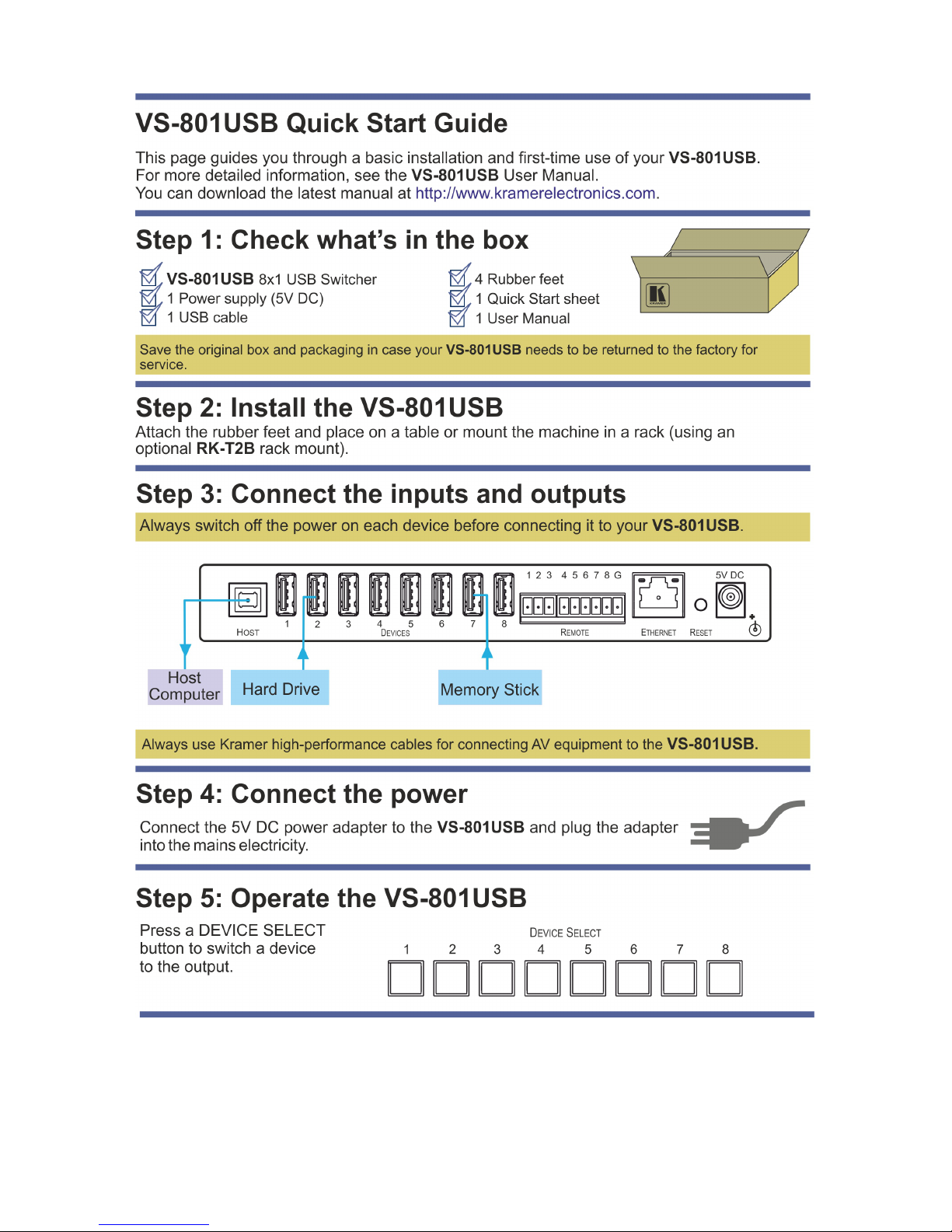
Congratulations on purchasing your Kramer VS-801USB 8x1 USB Switcher,
which is ideal for educational institutions, presentation and display systems and
home theater applications.

2 VS-801USB - Getting Started
2 Getting Started
We recommend that you:
• Unpack the equipment carefully and save the original box and packaging
materials for possible future shipment
• Review the contents of this user manual
Use Kramer high performance high resolution cables
i
Go to http://www.kramerelectronics.com to check for up-to-date
user manuals, application programs, and to check if firmware
upgrades are available (where appropriate).
2.1 Achieving the Best Performance
To achieve the best performance:
• Use only good quality connection cables to avoid interference, deterioration
in signal quality due to poor matching, and elevated noise levels (often
associated with low quality cables)
• Avoid interference from neighboring electrical appliances that may adversely
influence signal quality
• Do not secure the cables in tight bundles or roll the slack into tight coils
• Position your Kramer VS-801USB away from moisture, excessive sunlight
and dust
!
Caution: No operator serviceable parts inside the unit
Warning:
Use only the Kramer Electronics input power wall
adapter that is provided with the unit
Warning:
Disconnect the power and unplug the unit from the
wall before installing

VS-801USB - Overview 3
3
3 Overview
The Kramer VS-801USB is a high quality 8x1 USB switcher. It accepts up to eight USB
devices and switches the selected device to the host.
In particular, the VS-801USB features:
• Hi speed USB revision 2.0
• Eight DEVICE SELECT buttons
• Firmware upgrade via RS-232
• Remote control via the RS-232 port, the RC-IR3 IR remote control
transmitter, the Ethernet and/or remote contact closure
• An external 5V DC source, making it suitable for field operation
The VS-801USB is housed in a compact MegaTOOLS™ enclosure, enabling two
units to be rack mounted side-by-side in a 1U rack space using the optional
RK-T2B universal rack adapter.
4 VS-801USB - Overview
3.1 Defining the VS-801USB 8x1 USB Switcher
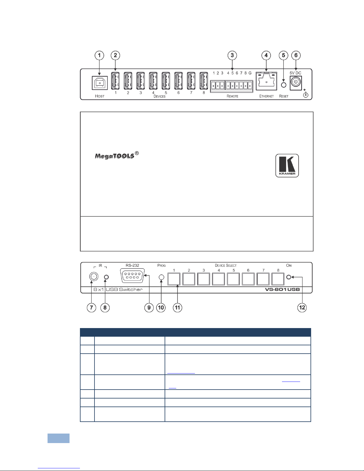
Figure 1: VS-801USB 8x1 USB Switcher
#
Feature
Function
1 HOST USB (type B) Port Connects to the host
2 DEVICE USB (type A) port Connects to a USB device (from 1 to 8)
3 REMOTE Switch Terminal
Block
Connect to contact closure switches for duplicating the
function of the front panel DEVICE SELECT buttons (see
Section
5.2)
4 ETHERNET RJ-45
Connector
Connect to a remote controller via a LAN (see Section
4.2)
5 RESET Button Reset to the Ethernet factory default values
6 5V DC +5V DC connector for powering the unit
7 IR Receiver Receives signals from the infrared remote control
transmitter

VS-801USB - Overview 5
5
#
Feature
Function
8 IR LED The yellow LED lights when receiving IR signals
9 RS-232 9-pin D-sub
Connector
Connects to a PC for firmware upgrade and control
10 PROG Push in for “Program” using a small screwdriver to
upgrade to the latest Kramer firmware via RS-232, or
release for “Normal” (the factory default)
11 DEVICE SELECT Buttons Select a device to switch to the host (from 1 to 8)
12 ON LED Illuminates green when receiving power
 Loading...