

Page 1

Kramer Electronics, Ltd.
USER MANUAL
Model:
VS-3232D
32x32 Digital Matrix Switcher
Page 2

Contents
i
Contents
1 Introduction 1
2 Getting Started 1
2.1 Quick Start 2
3 Overview 3
3.1 Defining EDID 4
3.2 Recommendations for Best Performance 4
4 Defining the VS-3232D 32x32 Digital Matrix Switcher 4
4.1 Using the IR Transmitter 8
5 Installing the VS-3232D in a Rack 9
6 Connecting the VS-3232D 32x32 Digital Matrix Switcher 10
6.1 Port Numbering 11
6.1.1 EDID Numbering Examples 12
6.2 Connecting to the VS-3232D via RS-232 13
6.3 Connecting to the VS-3232D via Ethernet 13
6.3.1 Connecting the Ethernet Port directly to a PC 13
6.3.2 Connecting to the Ethernet Port via a Network Switch/Hub 15
7 Operating Your Video Matrix Switcher 15
7.1 Startup Display 15
7.1.1 Viewing the Display 16
7.2 Using the Selector Buttons 16
7.3 Confirming Actions 16
7.3.1 Toggling between the At Once and Confirm Modes 17
7.3.2 Confirming a Switching Action 17
7.4 Switching Actions 17
7.4.1 Switching one Input to one Output 18
7.4.2 Switching Several Inputs to Several Outputs 18
7.4.3 Turning an Output Off 18
7.4.4 Turning Off Several Outputs 19
7.4.5 Recalling the Default Setup 19
7.5 Locking the Front Panel Buttons 20
8 Using the Configuration Menus 20
8.1 Using the Setup Menu 20
8.1.1 Setup Menu—1: inXX=>ALL, Switching one Input to all Outputs 21
8.1.2 Setup Menu—3: outXX=>OFF, Turning an Output Off 21
8.1.3 Setup Menu—7: EDID, Assignment to an Input 21
8.1.4 Setup Menu—9: Delay, Setting for an Output 22
8.1.5 Setup Menu—4: store setup XX, Storing the Setup in a Preset 23
8.1.6 Setup Menu—6: recall setup XX, Recalling a Preset 23
8.2 Using the Config Menu 24
8.2.1 Config Menu—Input Signal Detection Display 25
8.2.2 Config Menu—Output Load Detection Display 25
Page 3

KRAMER: SIMPLE CREATIVE TECHNOLOGY
Contents
ii
8.2.3 Config Menu—Interface Configuration 26
8.2.4 Config Menu—Interface Reply Configuration 26
8.2.5 Config Menu—Protocol Configuration 27
8.2.6 Config Menu—Store Default Setup 27
8.2.7 Config Menu—Total Matrix Reset 27
8.2.8 Config Menu—Display Firmware Versions 28
9 Configuring the Number of Installed Input and Output Ports 29
10 Installing and Using the Test Module to Troubleshoot Video Problems 29
10.1 Installing the Test Module 29
10.2 Setting the Resolution of the Generated Video 30
10.3 Setting the Pattern of the Generated Video 31
10.4 Using the Test Module to Troubleshoot Video Problems 31
10.4.1 Testing the Projector Output 31
10.4.2 Testing the Output Signal Path to the Projector 32
10.4.3 Testing the Input and Output Signal Path to the Projector 32
11 I/O Card Hardware Installation Instructions 32
12 Upgrading the VS-3232D Firmware 34
13 Technical Specifications 35
14 Default Communication Parameters 36
15 Factory Default EDID 36
15.1 DVI Input Card 36
15.2 DVI (HDCP) Input Card 37
15.3 HDMI Input Card 39
15.4 DVI Dual Channel Input Card 41
16 Communication Protocols 41
Figures
Figure 1: VS-3232D 32x32 Digital Matrix Switcher Front Panel 5
Figure 2: VS-3232D Front Panel Numeric Keypad
6
Figure 3: VS-3232D 32x32 Digital Matrix Switcher Rear Panel Showing DVI Cards 7
Figure 4: Connecting the VS-3232D
10
Figure 5: Sample Port Numbering
12
Figure 6: Local Area Connection Properties Window
14
Figure 7: Internet Protocol (TCP/IP) Properties Window 14
Figure 8: Default Startup Status Display Sequence
15
Figure 9: Resolution DIP-switch
30
Figure 10: Signal Paths for Isolating problems
31
Figure 11: Inserting the Card into a Slot
33
Figure 12: Card Handles 34
Page 4

Contents
iii
Tables
Table 1: VS-3232D 32x32 Digital Matrix Switcher Front Panel Features 6
Table 2: VS-3232D Front Panel Numeric Keypad Labels 6
Table 3: VS-3232D 32x32 Digital Matrix Switcher Rear Panel Features
8
Table 4: Port Numbering
12
Table 5: EDID Configuration Requests and Results
13
Table 6: Available PC Resolutions for Generated Video (Jumper off) 30
Table 7: Available HDResolutions for Generated Video (Jumper on, default)
30
Table 8: Technical Specifications of the 32x32 Digital Matrix Switcher
35
Table 9: Technical Specifications of VS-3232D Compatible Cards
35
Table 10: Default Communication Parameters for the VS-3232D 36
Table 11: Hex Table (IN 1-32 to OUT 1-16)
41
Table 12: Hex Table (IN 1-32 to OUT 17-32)
43
Page 5

Introduction
1
1 Introduction
Welcome to Kramer Electronics! Since 1981, Kramer Electronics has been
providing a world of unique, creative, and affordable solutions to the vast range of
problems that confront the video, audio, presentation, and broadcasting
professional on a daily basis. In recent years, we have redesigned and upgraded
most of our line, making the best even better! Our 1,000-plus different models now
appear in 11 groups
1
Congratulations on purchasing your Kramer VS-3232D 32x32 Digital Matrix
Switcher. This product is ideal for the following typical applications:
that are clearly defined by function.
• Professional display systems requiring video signal routing
• Broadcast, presentation and production facilities, as well as monitoring in
large duplication systems
• Rental/staging applications
The package includes the following items:
• VS-3232D 32x32 Digital Matrix Switcher
• Power cord
• Kramer RC-IR3 infrared remote control transmitter (including the required
batteries and a separate user manual
2
)
• This user manual
2
Note: Throughout this user manual the chassis configuration is shown with 32 DVI
inputs and 32 DVI outputs as a representation only. The following cards are
available and may be mixed in the same chassis:
• DVI
• DVI dual link
• DVI (HDCP)
• DVI (over 4LC fiber optic cable)
• HDMI (HDCP)
2 Getting Started
We recommend that you:
• Unpack the equipment carefully and save the original box and packaging
materials for possible future shipment
• Review the contents of this user manual
1 GROUP 1: Distribution Amplifiers; GROUP 2: Switchers and Matrix Switchers; GROUP 3: Control Systems; GROUP 4:
Format/Standards Converters; GROUP 5: Range Extenders and Repeaters; GROUP 6: Specialty AV Products; GROUP 7: Scan
Converters and Scalers; GROUP 8: Cables and Connectors; GROUP 9: Room Connectivity; GROUP 10: Accessories and Rack
Adapters; GROUP 11: Sierra Products
2 Download up-to-date Kramer user manuals from
http://www.kramerelectronics.com
Page 6
KRAMER: SIMPLE CREATIVE TECHNOLOGY
Getting Started
2
• Use Kramer high-performance high-resolution cables
1
• Use only the power cord that is supplied with this machine
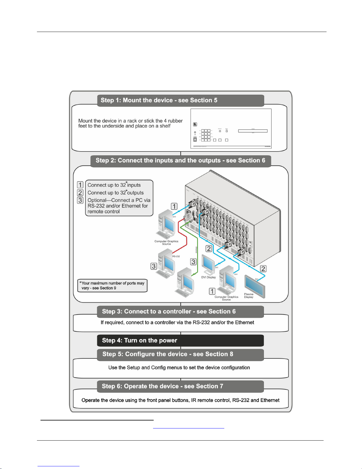
2.1 Quick Start
The following quick start chart summarizes the basic setup and operation steps.
1 The complete list of Kramer cables is available from http://www.kramerelectronics.com
Page 7

Overview
3
3 Overview
The Kramer VS-3232D is a high performance matrix switcher chassis that supports
up to 32 x 32 ports
1
for various signals (depending on the type of cards installed).
It features a very high bandwidth
2
The VS-3232D is highly configurable–you can add or remove inputs and outputs
independently in groups of four and mix different types of input/ouput cards in the
same chassis. For example, you can configure a device as a 4 x 24 or a 32 x 8
matrix switcher to exactly suit your needs.
of up to 3.2Gbps (for the chassis only, effective
bandwidth of the system depends on the I/O cards) that ensures transparent
performance even in the most critical applications. The cards re-clock and equalize
the signals and the chassis can route any or all inputs to any or all outputs
simultaneously.
The VS-3232D features:
• Full 32 x 32 non-blocking matrix array to switch any of the 32 input digital
signals to any or all outputs (with limitations, see Section
6)
• Easy access to 59 preset memory locations for quick access to user-defined
setups
• The Kramer 2000 Protocol for serial control
• A 40 character by 2 line LCD that shows the operational status or the
configuration menu
• A lock function to prevent tampering with the front panel
• A default EDID (Extended Display Identification Data) for each input
• I-EDIDPro™ Kramer Intelligent EDID Processing™ – Intelligent EDID
handling and processing algorithm ensures plug and play operation for
DVI/HDMI systems
• Kramer Core™—flexible infrastructure conversion. Copper, fiber or
Twisted Pair, all can be used at the same time according to input/output
module selection. The matrix receives digital signals from compatible
Kramer transmitters, automatically converts between available infrastructure
options and sends the signals to compatible Kramer receivers
• Equalization and re-clocking on all card types
You can operate the VS-3232D via the front panel buttons
3
• RS-232 serial commands transmitted by a touch screen system, PC or other
serial controller
or remotely via:
1 Can also be configured for other sizes (up to a maximum of 32 x 32)
2 For maximum bandwidth supported by each type of card see the Technical Specifications in Section
13
3 The VS-3232D is a sophisticated device but has been designed to be as simple as possible to operate. Due to space limitations on the
front panel 64 input/output selector buttons are instead substituted by a keypad. For details of how to route inputs to outputs, see
Section
7.2
Page 8

KRAMER: SIMPLE CREATIVE TECHNOLOGY
Defining the VS-3232D 32x32 Digital Matrix Switcher
4
• Ethernet over a LAN
• The infrared remote control transmitter
The VS-3232D is housed in a 19" rack-mountable enclosure.
To achieve the best performance:
• Connect only good quality connection cables, thus avoiding interference,
deterioration in signal quality due to poor matching, and elevated noise
levels (often associated with low quality cables)
• Avoid interference from neighboring electrical appliances that may
adversely influence signal quality
• Position your Kramer VS-3232D in a location free from moisture and away
from excessive sunlight and dust
3.1 Defining EDID
The Extended Display Identification Data (EDID
1
3.2 Recommendations for Best Performance
) is a data-structure provided by
a display, to describe its capabilities to a graphics card (that is connected to the
display’s source). The EDID enables the video source to “know” what kind of
monitor is connected to the output. The EDID includes the manufacturer’s name,
the product type, the timing data supported by the display, the display size,
luminance data and (for digital displays only) the pixel mapping data.
To achieve the best performance:
• Use only good quality connection cables to avoid interference, deterioration
in signal quality due to poor matching, and elevated noise levels (often
associated with low quality cables)
• Avoid interference from neighboring electrical appliances that may
adversely influence signal quality and position your Kramer VS-3232D
away from moisture, excessive sunlight and dust
4 Defining the VS-3232D 32x32 Digital Matrix Switcher
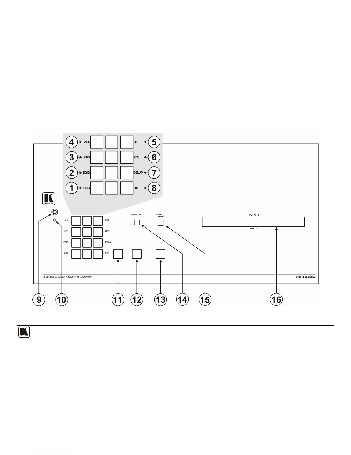
Figure 1, Table 1, Figure 2 and Table 2 define the front panel of the VS-3232D.
1 Defined by a standard published by the Video Electronics Standards Association (VESA)
Page 9
Defining the VS-3232D 32x32 Digital Matrix Switcher
5
Figure 1: VS-3232D 32x32 Digital Matrix Switcher Front Panel
Note: Buttons 11, 12 and 13 function as the TAKE, MENU and LOCK buttons respectively
Page 10

KRAMER: SIMPLE CREATIVE TECHNOLOGY
Defining the VS-3232D 32x32 Digital Matrix Switcher
6
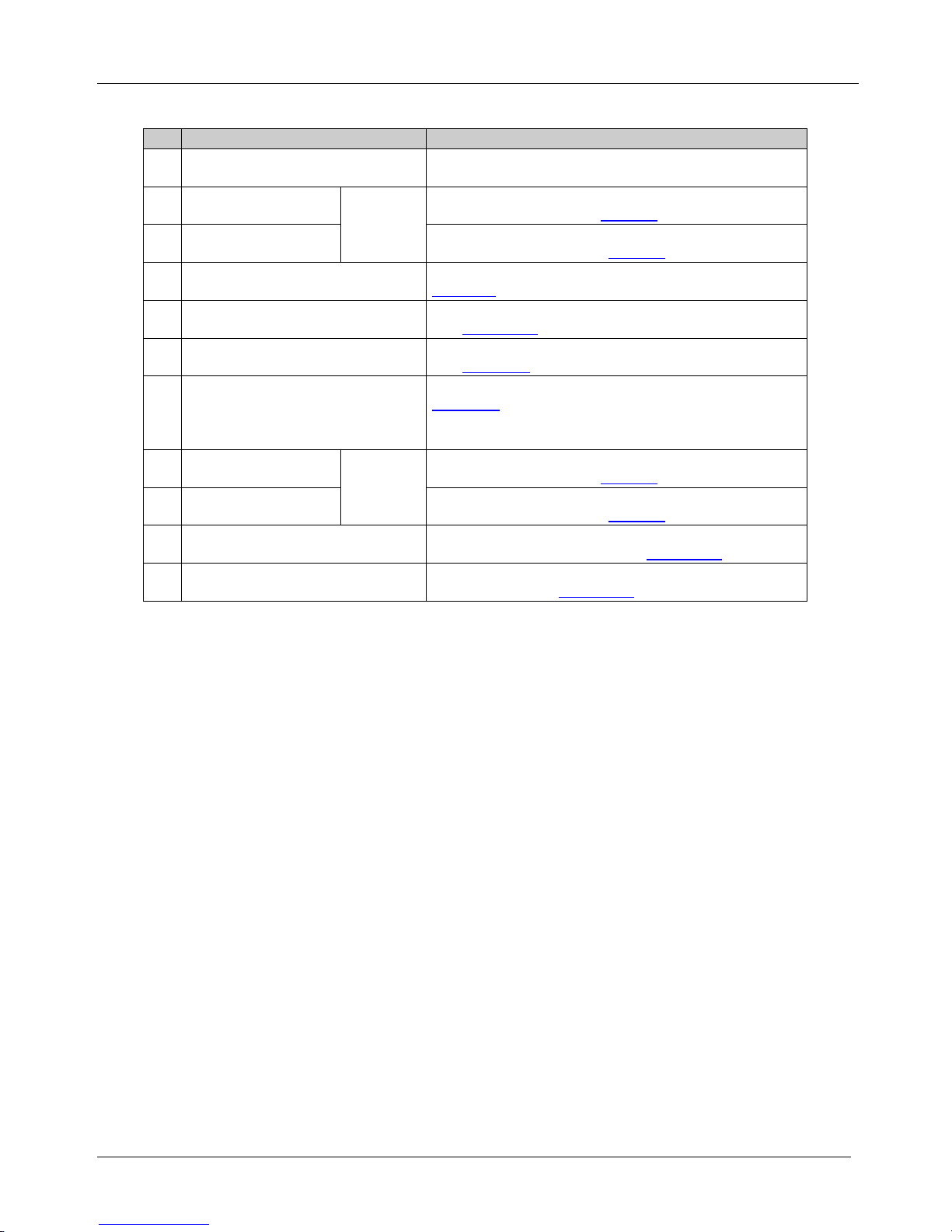
Table 1: VS-3232D 32x32 Digital Matrix Switcher Front Panel Features
#
Feature
Function
1
Doublefunction
Selector
Buttons
Area
Menu
Buttons
ESC Press to exit the current operation
2 EDID Press to assign EDID channels
3 STO
1
Press to store the current setup in the a preset
4 ALL1 Press to connect an input to all outputs
5 OFF1 Press to turn off an output
6 RCL1 Press to recall a preset
7 DELAY Press to set the delay between confirming an action and the execution of the action
8 ENT Press to complete the input-output setup when using a one-digit number instead of
two digits
2
Press to enter the options in a setup menu
.
9 IR Receiver Infrared remote control sensor
10 IR LED Lights yellow when receiving commands from the IR remote control transmitter
11 TAKE Button Press to confirm actions (see Section 7.3.2
12
)
MENU Button Press once to enable the ALL, OFF STO and RCL buttons (see Section 8).
Press again to enter the configuration menu (see
8.2Section
When in a Menu, press to cycle through the menu items
).
13 LOCK Button Press and hold for approximately 2 sec to lock/unlock the front panel buttons (see
Section 7.5
14 ) BREAKAWAY Button Press to exit a Menu (see Section 8
15 ) DEFAULT SETUP Button Press to recall the default setup (see Section 7.4.5
16
)
OUTPUTS/INPUTS
LCD Display
Displays the outputs (upper row) switched to the selected inputs (lower row), (see
Section 7.1
Displays user interface messages and menus
).
Figure 2: VS-3232D Front Panel Numeric Keypad
Table 2: VS-3232D Front Panel Numeric Keypad Labels
# Feature Function
17 ◄ (Backward) Press to shift the sliding window to the right3
18 1, 2, 3, 4, 5, 6, 7, 8, 9, 0 Numeric keypad, 1 to 0
19 ► (Forward) Press to shift the sliding window to the left
3
1 After pressing the MENU button, this button lights and is enabled
2 For example, to enter input 5, you can either press 05 or 5, ENT
3 Since the LCD display is large enough to show only 13 cross-points out of a total of 32
Page 11
Defining the VS-3232D 32x32 Digital Matrix Switcher
7
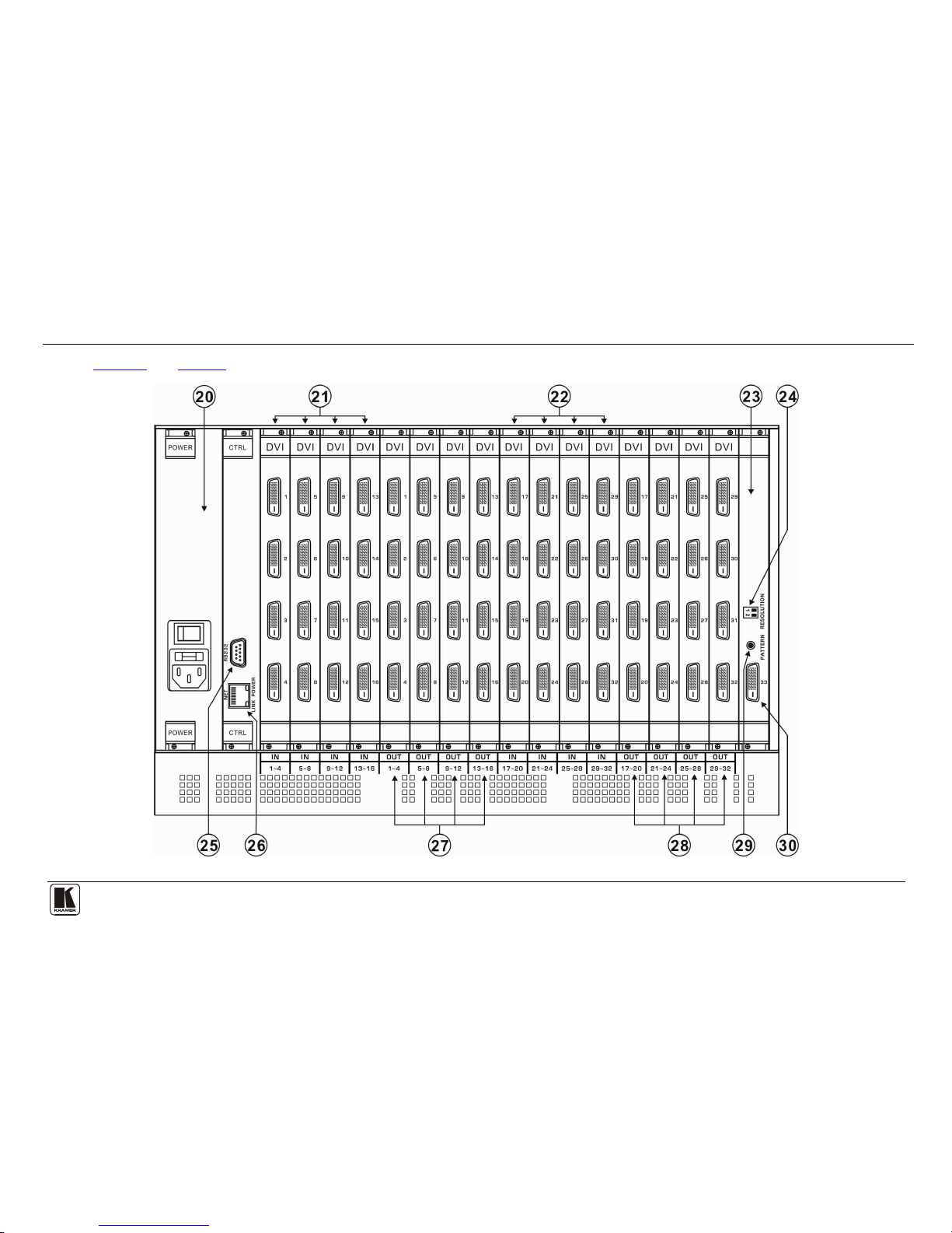
Figure 3 and Table 3 define the rear panel of the VS-3232D showing DVI cards installed as an example.
Figure 3: VS-3232D 32x32 Digital Matrix Switcher Rear Panel Showing DVI Cards
Page 12
KRAMER: SIMPLE CREATIVE TECHNOLOGY
Defining the VS-3232D 32x32 Digital Matrix Switcher
8
Table 3: VS-3232D 32x32 Digital Matrix Switcher Rear Panel Features
#
Feature
Function
20 AC Mains Power Module Fuse holder and power cord socket. Connect to the AC
mains supply
21 IN 1~16 Connectors
INPUTS
Connect to the relevant video sources, depending on the
cards installed (1 to 16, see
Section 6
22 ) IN 17~32 Connectors Connect to the relevant video sources, depending on the
cards installed (17 to 32, see
Section 6
23 ) TEST Module Signal generator module for testing video outputs (see
Section 10
24 ) RESOLUTION DIP-switches Set the resolution for video generated by the Test module
(see
Section 10.2
25 ) RS-232 9-pin D-sub Port Connects to the remote operation PC or remote controller
(see
Section 6.1
26 ) NET Ethernet RJ-45 Connector Connect to a PC or controller via the Ethernet LAN (see
Section 6.3
The LINK LED flashes when communication is active.
POWER LED lights when the interface receives power
).
27 OUT 1~16 Connectors
OUTPUTS
Connect to the relevant video acceptors, depending on the
cards installed (1 to 16, see
Section 6
28 ) OUT 17~32 Connectors Connect to the relevant video acceptors, depending on the
cards installed (17 to 32, see
Section 6
29 ) PATTERN Button Press the button repeatedly to change the video pattern
generated by the Test module (see
Section 10.3
30 ) Test Module Output Connector Connect to one of the relevant video inputs to aid in
troubleshooting (see
Section 10.4
4.1 Using the IR Transmitter
)
You can use the RC-IR3 IR transmitter to control the machine via the built-in IR
receiver on the front panel.
Page 13

Installing the VS-3232D in a Rack
9
5 Installing the VS-3232D in a Rack
This section provides instruction on rack mounting the VS-3232D.
Page 14
KRAMER: SIMPLE CREATIVE TECHNOLOGY
Connecting the VS-3232D 32x32 Digital Matrix Switcher
10
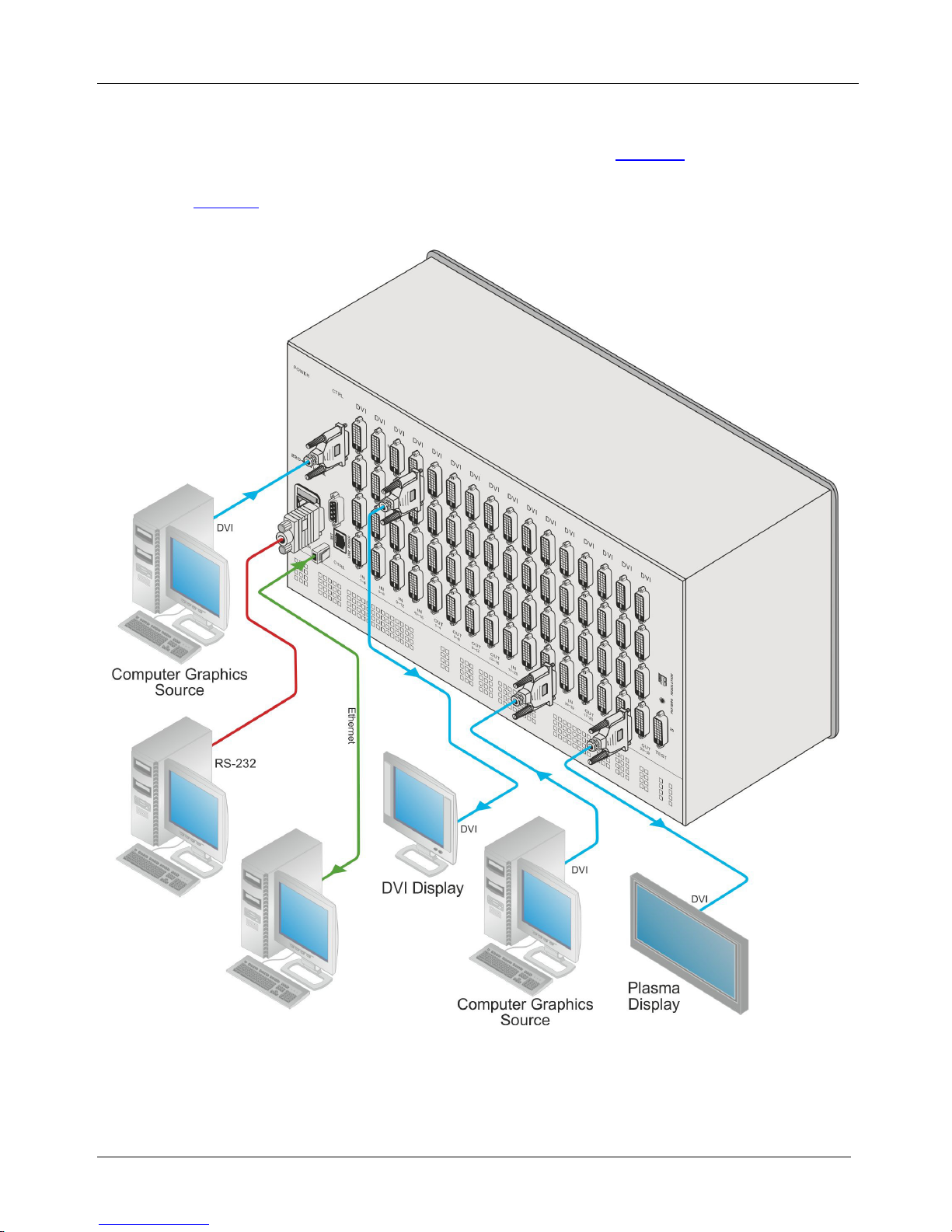
6 Connecting the VS-3232D 32x32 Digital Matrix Switcher
The configuration of DVI input/output cards shown in Figure 4 is merely a sample
representation and different I/O cards may be mixed as required (for limitations,
see
page 11). Exactly the same principles apply to installations using other card
types.
Figure 4: Connecting the VS-3232D
Page 15

Connecting the VS-3232D 32x32 Digital Matrix Switcher
11
To install1 the VS-3232D as illustrated in the example in Figure 4:
1. Connect up to 32 DVI video sources (for example
2
2. Connect up to 32 DVI video acceptors, (for example
, computer graphics
sources).
2
, a plasma display and a
DVI LCD display).
3. If required, connect a PC or remote controller to the RS-232 port (see
Section 6.1) and/or the Ethernet port (see 6.3Section
4. Connect the power cord
).
3
5. If necessary, review and set the system configuration using the Menu (see
.
Section 8
Note: Given an input signal that is HDCP encoded, the VS-3232D will output a
signal only if the output port to which it is switched support HDCP.
).
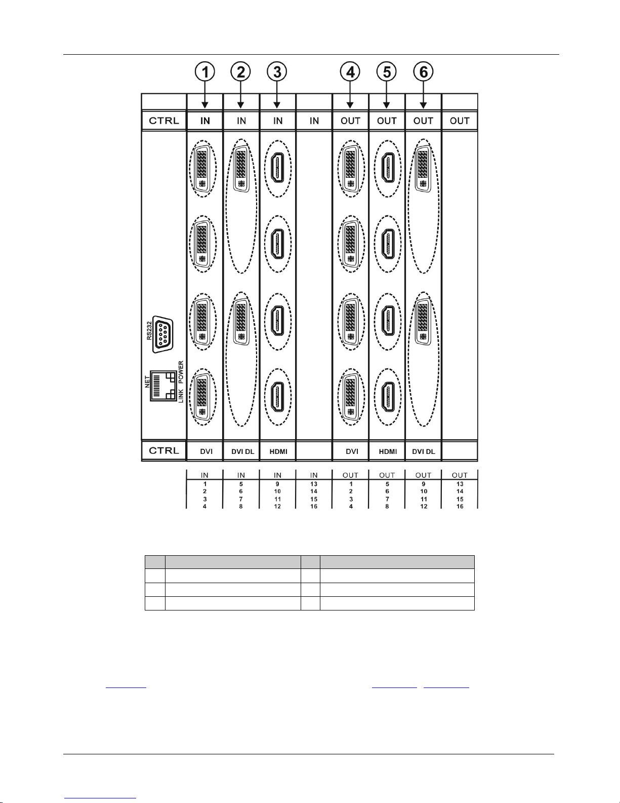
6.1 Port Numbering
On all cards apart from the DVI dual link cards, there are four physical ports and
the numbering of ports is sequential from top to bottom and left to right. Each DVI
dual link card provides two physical ports which causes the loss of two numbers in
the numbering sequence of that card only. A sample numbering is shown in
Figure 5 and explained in Table 4.
1 Switch off the power for each device before connecting it to your VS-3232D
2 In this example only two inputs and two outputs are connected
3 We recommend that you use only the power cord that is supplied with the device (not shown in
Figure 4)
Page 16
KRAMER: SIMPLE CREATIVE TECHNOLOGY
Connecting the VS-3232D 32x32 Digital Matrix Switcher
12
Figure 5: Sample Port Numbering
Table 4: Port Numbering
#
Port Number
#
Port Number
1 IN 1, IN 2, IN 3, IN 4 4 OUT 1, OUT 2, OUT 3, OUT 4
2 IN 5, IN 6 5 OUT 5, OUT 6, OUT 7, OUT 8
3 IN 9, IN 10, IN 11, IN 12 6 OUT 9, OUT 10
Note: There is no IN 7, IN 8, OUT 11 or OUT 12 because these slots contain DVI
dual link cards.
6.1.1 EDID Numbering Examples
Table 5 is based on the port numbering shown in Figure 5. Figure 7 lists EDID
configuration requests and the results.
Page 17

Connecting the VS-3232D 32x32 Digital Matrix Switcher
13
Table 5: EDID Configuration Requests and Results
EDID Request
EDID Sent
From OUT 11 Blank (256 bytes of 0xFF)
From IN 13 None (error message displayed)
6.2 Connecting to the VS-3232D via RS-232
You can connect to the VS-3232D via an RS-232 connection using, for example, a
PC. Note that a null-modem adapter/connection is not required
1
To connect to the VS-3232D via RS-232:
.
• Connect the RS-232 9-pin D-sub rear panel port on the VS-3232D unit via a
9-wire straight cable (only pin 2 to pin 2, pin 3 to pin 3, and pin 5 to pin 5
need to be connected) to the RS-232 9-pin D-sub port on your PC
6.3 Connecting to the VS-3232D via Ethernet
You can connect the VS-3232D via Ethernet using a crossover cable (see
Section 6.3.1) for direct connection to the PC, or a straight through cable (see
6.3.2Section ) for connection via a network hub or network router
2
6.3.1 Connecting the Ethernet Port directly to a PC
.
You can connect the Ethernet port on the VS-3232D to the Ethernet port on your
PC via a crossover cable with RJ-45 connectors.
This type of connection is recommended for identification of the factory default
IP Address of the VS-3232D during the initial configuration
To configure your PC after connecting the Ethernet port:
1. Right-click the My Network Places icon on your desktop.
2. Select Properties.
3. Right-click Local Area Connection Properties.
4. Select Properties.
The Local Area Connection Properties window appears.
5. Select the Internet Protocol (TCP/IP) and click the Properties Button.
1 Note that some early devices require a null modem
2 After connecting the Ethernet port, you have to install and configure your Ethernet Port. For detailed instructions, see the Ethernet
Configuration Guide (Lantronix) in the technical support section on our Web site
http://www.kramerelectronics.com
Page 18

KRAMER: SIMPLE CREATIVE TECHNOLOGY
Connecting the VS-3232D 32x32 Digital Matrix Switcher
14
Figure 6: Local Area Connection Properties Window
6. Select Use the following IP Address and enter the details as shown in
Figure 7.
Figure 7: Internet Protocol (TCP/IP) Properties Window
7. Click OK.
Page 19

Operating Your Video Matrix Switcher
15
6.3.2 Connecting to the Ethernet Port via a Network Switch/Hub
To connect to the Ethernet port on the VS-3232D via a network switch/hub:
• Connect the PC to the Ethernet network switch/hub using a straight through
cable
7 Operating Your Video Matrix Switcher
This section describes:
• The startup display (see
Section 7.1
• Using the selector buttons (see ) Section 7.2
• Confirming actions (see ) Section 7.3
• Switching options (see ) Section 7.4
• Locking the front panel (see ) Section 7.5
7.1 Startup Display
)
After switching on the power, the LCD display
1
shows the following screens in
sequence.
Figure 8: Default Startup Status Display Sequence
The front panel of the VS-3232D includes a numeric keypad within the selector
buttons area
2
. This keypad lets you enter both the output and input numbers as well
as various numeric configuration values (see
Section 7.2
When the unit is powered-on, the last matrix setup that was used is loaded. Use
either the recall setup
).
3
(see Section 8.1.6) or default setup recall
4
7.4.5
(see
Section
1 The text in the LCD Display may vary (according to machine settings)
) functions to retrieve other setups.
2 See Table 1
3 Records a stored configuration from a preset
4 For quick retrieval, you can program a default setup that is commonly used
Page 20

KRAMER: SIMPLE CREATIVE TECHNOLOGY
Operating Your Video Matrix Switcher
16
7.1.1 Viewing the Display
Figure 8 shows the output-input matrix on the LCD display. The LCD display can
show 13 out of the 32 available matrix combinations at once. To view any of the
matrix combinations use the ◄ or the ► buttons on the front panel to shift the
sliding window to the right or left.
This sliding window functionality is enabled when:
• The switcher is in between operations
1
• Recalling a setup using the ◄ or ► buttons
When entering an output/input combination, the contents of the LCD display
automatically shift to indicate the current status of the selected output.
7.2 Using the Selector Buttons
For numbers between 1 and 9, the VS-3232D can handle two digit numbers as well
as single digit numbers. When entering a single digit number (for example 5), you
can either press 0 followed by 5, or 5 followed by ENT.
Pressing 00 (or 0, ENT) is only relevant for an input selection and is used to
disconnect the currently entered output number from the input.
For example, the following display indicates that inputs 8 and 12 are disconnected
from any output (note that in the second line representing these inputs the display
is blank):
06 07 08 09 10 11 12 13
12
08 10 14 13 06
The ESC button is used to cancel an operation without affecting the current status.
For example, if you enter an incorrect number by mistake, press the ESC button to
cancel the operation.
Note: At any stage, if no button is pressed within approximately 15 seconds, the
automatic timeout causes the VS-3232D to exit the operation and revert to the
output/input display.
7.3 Confirming Actions
You can choose to work in the At Once (default
2
In the At Once mode:
) or the Confirm mode.
• The TAKE button does not light
• Pressing an OUT-IN combination implements the switch without further
user confirmation
1 Waiting for its next operation while all previous operations are complete or cancelled
2 For all actions except storing/recalling
Page 21

Operating Your Video Matrix Switcher
17
• You save time as execution is immediate and actions require no user confirmation
• No protection is offered to correct an erroneous action
In the Confirm mode:
• The TAKE button lights
• You enter an action and then confirm it by pressing the TAKE button
• Every action requires user confirmation, protecting against erroneous actions
• Execution is postponed until you confirm the action
1
7.3.1 Toggling between the At Once and Confirm Modes
To toggle between the At Once and Confirm modes:
Note: If the TAKE button is flashing you cannot toggle between the At Once and
Confirm modes. A flashing TAKE button indicates that an action is currently
pending confirmation.
1. Press TAKE to toggle between the At Once mode and the Confirm mode.
The TAKE button lights and actions now require user confirmation.
2. Press the lit TAKE button to toggle from the Confirm mode back to the At
Once mode.
The TAKE button is no longer lit and actions no longer require user
confirmation.
7.3.2 Confirming a Switching Action
Actions only require confirmation when the device is in the Confirm mode.
To confirm a switching action:
1. Using the numeric keypad, enter an output-input combination.
The TAKE button flashes.
2. Press the flashing TAKE button to confirm the action.
The action is confirmed and the TAKE button lights.
7.4 Switching Actions
This section describes how to:
• Switch one input to one output (see
Section 7.4.1
• Switch several inputs to several outputs (see ) Section 7.4.2
• Turn off several outputs (see ) Section 7.4.3
)
1 Failure to press the TAKE button within a few seconds results in the action timing out automatically
Page 22

KRAMER: SIMPLE CREATIVE TECHNOLOGY
Operating Your Video Matrix Switcher
18
7.4.1 Switching one Input to one Output
To switch one input to one output:
1. Using the numeric keypad, enter the required output (in this example, 12).
The following is displayed:
06 07 08 09 10 11 12 13
In__ => Out 12
The left-hand side of the display shows a section of the output/input display
automatically sliding the content to include output 12.
2. Using the numeric keypad, enter the required input (in this example, 14):
In the At Once mode, the switching takes place immediately and the
LCD display shows a segment of the input-output status that includes the
switched input and output (for example, 14-12)
In the Confirm mode, the LCD display shows the following:
In 14 => Out 12
Incomplete actions time out after approximately 15 seconds.
In the Confirm mode, press the flashing TAKE button to switch the input
to the output
7.4.2 Switching Several Inputs to Several Outputs
If you want to switch several inputs to several outputs simultaneously you must be
in the Confirm mode.
In the Confirm mode you can enter a batch of several actions and then confirm the
batch by pressing TAKE once (simultaneously switching several output-input
combinations).
To switch several inputs to several outputs in the Confirm mode:
1. Using the numeric keypad, enter an output-input combination.
The TAKE button flashes.
2. Enter additional output-input combinations.
The LCD display can show up to five pending actions (although the batch is
not limited to five actions)
1
09 => 06 05 => 07
:
3. After entering all output/input combinations, press the flashing TAKE button
to confirm the actions.
The inputs switch to the respective outputs as shown on the LCD display and
the TAKE LED is lit.
7.4.3 Turning an Output Off
Turning an output off means that there is no input switched to this output. This is
indicated on the display by the Input being blank underneath the relevant Output.
1 In this example, input 9 is set to switch to output 6 and input 5 is set to switch to output 7
Page 23

Operating Your Video Matrix Switcher
19
To turn an output off:
1. Press MENU.
The Menu buttons light and are enabled.
2. Press OFF (3) on the numeric keypad (see
Figure 2).
The following message is displayed:
out__ => OFF
3. Use the numeric keypad to turn the required output off.
The output is turned off.
To turn an output off in the Confirm mode:
• Repeat the steps above and then press the flashing TAKE button to confirm
the action
Alternatively, you can perform a switching operation (see
Section 7.4.1
7.4.4 Turning Off Several Outputs
) and set
the input to 00.
To turn off several outputs in the Confirm mode, repeat the switching actions
described in
Section 7.4.2
7.4.5 Recalling the Default Setup
but set the inputs to 00.
You can store a commonly used setup as the default setup (see
Section 8.2.6
Note: This is not the setup that is loaded when the unit is turned on. When the unit
is turned on, the setup that was last used before the unit was turned off is loaded.
)
which can be recalled at any time.
To recall the default setup:
1. Press DEFAULT SETUP.
The DEFAULT SETUP button flashes and the following message is
displayed:
recall DEFAULT setup
press FLASHING button to confirm
2. Press DEFAULT SETUP.
The following message is displayed:
all Setups and Connections change
press TAKE to confirm
• The TAKE button flashes.
3. Press TAKE.
The default setup is recalled and the display reverts to the output-input
display.
Page 24

KRAMER: SIMPLE CREATIVE TECHNOLOGY
Using the Configuration Menus
20
7.5 Locking the Front Panel Buttons
You can lock
1
To lock the front panel buttons:
the VS-3232D to prevent tampering with the unit or prevent the
settings from being changed accidentally via the front panel buttons.
• Press and hold LOCK until the button lights.
The front panel buttons are locked
To unlock the front panel buttons:
• Press and hold LOCK until the button is no longer lit.
The front panel buttons are unlocked
8 Using the Configuration Menus
The configuration menus let you configure the VS-3232D to best suit your needs.
There are two configuration menus:
• Setup Menu—those that are accessed on a regular basis (for example,
storing setups and setting the delay), see
• Config Menu—those that are accessed only occasionally (for example,
setting the interface or communication protocol), see
Section 8.1
The following rules apply to the menu operation:
Section 8.2
• If no selection is made within approximately 15 seconds, the operation
times-out and the display reverts to the output/input display
• At any point in the Menu, press ESC to move up one level or press
BREAKAWAY to exit the Menu altogether
• At any point in the Menu, only buttons that are active light or flash
• All of the procedures in this section assume that you are starting the
procedure from the standard, operational output/input display
8.1 Using the Setup Menu
The Setup Menu provides access to settings that are regularly changed and
comprises the following options:
• 1: inXX=>ALL, switching one input to all outputs (see
Section 8.1.1
• 3: outXX=OFF, turning off an output (see ) Section 8.1.2
• 7: EDID, assignment to an output (see ) Section 8.1.3
• 9: Delay setting for an output (see ) Section 8.1.4
• 4: store setup XX, storing the setup in a preset (see ) Section 8.1.5
• 6: recall setup XX, recalling a preset (see ) Section 8.1.6
)
1 You can still remotely operate via RS-232 or Ethernet even when the front panel is locked
Page 25

Using the Configuration Menus
21
8.1.1 Setup Menu—1: inXX=>ALL, Switching one Input to all Outputs
This option switches one input to all outputs.
To switch one input to all outputs:
1. Press MENU.
The Setup Menu options are displayed.
2. Press 1 (ALL) on the numeric keypad (see
Figure 2
).
The following is displayed:
in__ => ALL
3. Using the numeric keys, enter the input to be switched to all outputs.
The TAKE button flashes.
4. Press TAKE.
The selected input is switched to all outputs.
The display reverts to the output/input display showing that the selected input
is switched to all outputs.
8.1.2 Setup Menu—3: outXX=>OFF, Turning an Output Off
This option turns an output off.
To turn an output off:
1. Press MENU.
The Setup Menu options are displayed.
2. Press 3 (OFF) on the numeric keypad (see
Figure 2).
The following is displayed:
out__ => OFF
3. Using the numeric keys, enter the output to be turned off.
The TAKE button flashes.
4. Press TAKE.
The selected output is turned off.
The display reverts to the output/input display showing that the selected
output is turned off with the input being blank.
8.1.3 Setup Menu—7: EDID, Assignment to an Input
This option assigns an EDID to between one and eight inputs. More than eight
EDID assignments must be assigned in separate batches of eight.
Each input on the VS-3232D has a factory default EDID loaded (see
Section 15).
The EDID for each input can be changed independently via the menu (described
below) or by uploading an EDID binary file to each input via the RS-232 port
using Kramer EDID Sender software
1
.
1 Available for download from http://www.kramerelectronics.com
Page 26

KRAMER: SIMPLE CREATIVE TECHNOLOGY
Using the Configuration Menus
22
To assign an EDID to between one and eight inputs:
1. Press MENU.
The Setup Menu options are displayed.
2. Press 7 (EDID) on the numeric keypad (see
Figure 2).
The following is displayed:
SETUP EDID
ENTER to View EDID and Set EDID
3. Press ENT.
The current EDID matrix configuration is displayed.
4. Using the numeric keys, enter the input in which to store the EDID (in this
example, 08), and enter the output (in this example, 05) from which to read
the EDID.
The following is displayed:
00 01 02 03 04 05 06 07 08
05 out05 => in08
The TAKE button flashes.
5. Repeat Step 4 for up to eight inputs.
6. Press TAKE.
The EDID is stored and passed through to the input.
The display reverts to the output/input display.
7. Repeat the above steps for th next batch of eight EDID assignments.
To view the EDID assignments:
1. Press MENU.
The Setup Menu options are displayed.
2. Press 7 (EDID) on the numeric keypad (see
Figure 2).
The following is displayed:
SETUP EDID
ENTER to View EDID and Set EDID
3. Press ENT.
The current EDID matrix configuration is displayed. In this example, input 07
is assigned to output 05, all other EDID values are default.
05 06 07 08 09 10
05
8.1.4 Setup Menu—9: Delay, Setting for an Output
Some displays require a delay in the negotiation of data between the display and
the switcher for reliable negotiation of data between them. This option sets the time
delay for an output which lapses between entering a switching action and the
execution of the action. This delay can be set for each output independently. The
delay is defined in units of 200ms and ranges from 0 to 15, providing delays of
between 0 and 3 seconds (15 x 200ms = 3 seconds).
Page 27

Using the Configuration Menus
23
To set the execution delay for an output:
1. Press MENU.
The Setup Menu options are displayed.
2. Press 9 (DELAY) on the numeric keypad (see
Figure 2).
The output/delay times display is shown.
3. Using the numeric keys, enter the output (in this example, 03).
The following is displayed:
01 02 03 04 05 06 07 08
DLY__ =>out03
4. Using the numeric keys, enter the number of delay units.
5. Press TAKE.
The selected output delay is set.
The display reverts to the output/input display.
8.1.5 Setup Menu—4: store setup XX, Storing the Setup in a Preset
This option stores the current setup in a preset (1 to 59).
To store the current setup in a preset:
1. Press MENU.
The Setup Menu options are displayed.
2. Press 4 (STO) on the numeric keypad (see
Figure 2).
The following is displayed:
store => __
3. Using the numeric keys, enter the preset (1 to 59) in which to store the current
setup.
The following is displayed:
Wait …..
After a few seconds, if the preset is not empty, the following is displayed:
SETUP NOT EMPTY
CONFIRM
The TAKE button flashes.
4. Press TAKE.
The setup is stored in the selected preset for subsequent recall.
The display reverts to the output/input display.
8.1.6 Setup Menu—6: recall setup XX, Recalling a Preset
This option recalls a stored configuration from a preset (1 to 59).
To recall a stored configuration:
1. Press MENU.
The Setup Menu options are displayed.
Page 28

KRAMER: SIMPLE CREATIVE TECHNOLOGY
Using the Configuration Menus
24
2. Press 6 (RCL) on the numeric keypad (see Figure 2).
The following is displayed:
recall <= __
3. Using the numeric keys, enter the preset (in this example, 02) to recall.
The following is displayed:
Wait …..
After a few seconds, the following is displayed on the right hand side:
CONFIRM
RECALL <= 02
The TAKE button flashes.
4. Press TAKE.
The preset is recalled.
The display reverts to the output/input display.
8.2 Using the Config Menu
The Config Menu provides access to configuration settings that are not regularly
changed and comprises the following options:
• Input signal detection (
Section 8.2.1
• Output load detection () Section 8.2.2
• Interface configuration () Section 8.2.3
• Interface Reply configuration () Section 8.2.4
• Protocol configuration () Section 8.2.5
• Storing the default setup () Section 8.2.6
• Resetting the VS-3232D () Section 8.2.7
• Firmware revision display () Section 8.2.8
To enter the Config Menu press MENU twice. The MENU button lights and the
following message is displayed:
)
• Start configuration menu
• MENU to view setups ENT to change them
When browsing through the configuration menu, enabled buttons light or flash.
Use the Config Menu as follows:
1. Press the MENU button to cycle through the menu items
1
2. Press the ENT button to enter a submenu.
.
3. After entering a submenu, you can select between several options.
Select an option by pressing one of the illuminated buttons in the Selector
Buttons area.
4. After selecting the desired option, a description of the desired change is
displayed and the TAKE button flashes.
1 The LCD display shows the current status of the selected menu item
Page 29

Using the Configuration Menus
25
5. Press the flashing TAKE button to confirm the change.
A description of the current state is displayed for about one second. The unit
automatically switches to the next item in the menu.
8.2.1 Config Menu—Input Signal Detection Display
This option displays a list of inputs and indicates on which of them signals have
been detected.
To display a list of inputs that have detected signals:
1. Press MENU twice.
The following message is displayed:
start configuration menu
MENU to view setup ENT to change them
2. Press MENU.
The following is displayed:
IN: 01 02 03 04 05 06 07 08 09 10 11
SIG: Y X Y Y Y Y X Y Y Y X
• Y indicates that a signal is detected and X indicates that no signal is detected
on the relevant input.
3. Do one of the following:
Press BREAKAWAY to exit the Config Menu
Wait approximately 15 seconds for the operation to time out
Press MENU to move to the next Config Menu option
8.2.2 Config Menu—Output Load Detection Display
This option displays a list of outputs and indicates which have loads attached to
them.
To display a list of outputs and attached loads:
1. Press MENU twice.
The following message is displayed:
start configuration menu
MENU to view setup ENT to change them
2. Press MENU until the following is displayed:
OUT: 01 02 03 04 05 06 07 08 09 10 11
LOAD: Y X Y Y Y Y X Y Y Y X
• Y indicates that a load is attached and X indicates that no load is detected on
the relevant output.
3. Do one of the following:
Press BREAKAWAY to exit the Config Menu
Wait approximately 15 seconds for the operation to time out
Press MENU to move to the next Config Menu option
Page 30

KRAMER: SIMPLE CREATIVE TECHNOLOGY
Using the Configuration Menus
26
8.2.3 Config Menu—Interface Configuration
This option lets you activate or deactivate the IR (infrared) and Ethernet interfaces.
To activate or deactivate the IR or Ethernet interfaces:
1. Press MENU twice.
The following message is displayed:
start configuration menu
MENU to view setup ENT to change them
2. Press MENU until the following is displayed:
INTERFACE configuration
current:IR-ON Ethernet-ON
The current status of the IR and Ethernet interfaces is displayed.
3. Press ENT to select the Interface Submenu.
4. Select 1 to modify the status of the IR interface or 2 to modify that status of
the Ethernet interface (in this example, 2).
The following is displayed:
Ethernet interface setup
1:make it ACTIVE 2:turn it OFF
5. Press 1 to activate the interface or 2 to deactivate it.
6. Press TAKE to confirm the action.
The interface status is changed. After a few seconds the next option on the
Config Menu is displayed.
8.2.4 Config Menu—Interface Reply Configuration
This option lets you switch the Reply configuration on or off. Setting Reply to on
causes all interfaces that are set to on to accept and execute commands, and also to
reply. Setting Reply to off causes all interfaces that are set to on to accept and
execute commands, but not to reply.
To switch the Reply configuration on or off:
1. Press MENU twice.
The following message is displayed:
start configuration menu
MENU to view setup ENT to change them
2. Press MENU until the following is displayed:
interface REPLY configuration
current interface REPLY – ON
This indicates the current Reply configuration status.
3. Press ENT to enter the Reply Submenu.
The following is displayed:
interface REPLY configuration
1:turn REPLY ON 2:never REPLY
Page 31

Using the Configuration Menus
27
4. Press 1 to switch Reply on or 2 to switch it off.
5. Press TAKE to confirm the action.
A message is displayed indicating the new status of the Reply configuration.
After a few seconds the next option on the Config Menu is displayed.
8.2.5 Config Menu—Protocol Configuration
The VS-3232D supports Kramer Protocol 2000. There are currently no options to
modify.
8.2.6 Config Menu—Store Default Setup
This option lets you store the current setup as the default setup. The default setup
can be recalled at any time using the DEFAULT SETUP button (see
Section 7.4.5
Note: This is not the setup that is loaded when the unit is switched on.
).
To store the current setup as the default setup:
1. Press MENU twice.
The following message is displayed:
start configuration menu
MENU to view setup ENT to change them
2. Press MENU until the following is displayed:
store DEFAULT setup
press ENTER to store
3. Press ENT to store the current configuration as the default configuration.
The following is displayed:
current matrix stage is OKAY?
press TAKE to confirm
4. Press TAKE.
The following is displayed:
current matrix stage
store as DEFAULT setup
• This indicates that the current setup is stored as the default setup. After a
few seconds the next option on the Config Menu is displayed.
8.2.7 Config Menu—Total Matrix Reset
This option lets you turn all outputs off or reset the unit to its factory default
settings.
To reset the matrix setup:
1. Press MENU twice.
The following message is displayed:
start configuration menu
MENU to view setup ENT to change them
Page 32

KRAMER: SIMPLE CREATIVE TECHNOLOGY
Using the Configuration Menus
28
2. Press MENU until the following is displayed:
TOTAL MATRIX RESET
exit = ESC ENT = submenu
3. Press ENT to enter the Reset Submenu.
The following is displayed:
COMPLETELY MATRIX RESET
1:ALL outputs OFF 2:Factory default
4. Press 1 to turn off all outputs or 2 to perform a factory reset of all options.
Caution: Selecting option 2 to perform a factory default reset clears all setups,
options and configuration.
5. Press TAKE and wait a few seconds.
The following is displayed:
Are you Absolutely sure !!!
Once more TAKE to confirm
6. Press TAKE.
The following is displayed:
Matrix erased!!!
Please, wait …
The matrix and device configuration are erased. After a few seconds the next
option on the Config Menu is displayed.
8.2.8 Config Menu—Display Firmware Versions
This option displays the main and front firmware versions.
To display the firmware versions:
1. Press MENU twice.
The following message is displayed:
start configuration menu
MENU to view setup ENT to change them
2. Press MENU until the following is displayed:
Main Firmware Version: 1.0
Front Firmware Version: 1.0
3. Either:
Press BREAKAWAY to exit the Config Menu
Wait approximately 15 seconds for the operation to time out
Page 33

Configuring the Number of Installed Input and Output Ports
29
9 Configuring the Number of Installed Input and Output Ports
After installing or removing a module you need to set the number of input and
output ports so that the VS-3232D recognizes the new configuration. Refer to
Section 6.1
To set the number of input or output ports:
for an explanation of port numbering before setting the number of input
and output ports.
1. Press ESC, ENT and LOCK together.
The following is displayed:
Configuration Device
2. Press ENT.
The following is displayed:
Test Board: 0 MaxInput:32 MaxOutput:32
Note: The number of input and output ports can only be set in units of four, for
example, 4 x 4, 32 x 4 or 12 x 16, and not 5 x 4 or 12 x 17.
3. Using the numeric keys, enter the number of input and output ports installed.
The TAKE button flashes.
4. Press TAKE.
The number of installed ports is saved and the display reverts to the
output/input display.
5. Reboot the device by turning the power off and then on again.
10 Installing and Using the Test Module to Troubleshoot Video
Problems
The VS-3232D includes a test module which acts as a signal generator and can be
used to diagnose video/audio issues in an operating environment.
The test module must be installed in the configuration before it can be used. When
installing the test module, the number of configured inputs and outputs must be
increased by one. For example:
• If your VS-3232D has four inputs and eight outputs, you must configure the
VS-3232D as 5 x 9
• If your VS-3232D has 32 inputs and 32 outputs, you must configure the
VS-3232D as 33 x 33
10.1 Installing the Test Module
To install the test module in the configuration:
1. Press ESC, ENT and LOCK together.
The following is displayed:
Configuration Device
Page 34

KRAMER: SIMPLE CREATIVE TECHNOLOGY
Installing and Using the Test Module to Troubleshoot Video Problems
30
2. Press ENT.
The following is displayed:
Test Board: 0 MaxInput:32 MaxOutput:32
where 0 indicates that the test module is not installed.
3. Using the numeric keys, press 1 to indicate that the test module is installed.
The TAKE button flashes.
4. Press TAKE.
5. Increase the number of configured inputs and outputs by one (see
Section 9
10.2 Setting the Resolution of the Generated Video
).
The test module is now installed and may be used.
The test module generates a range of both PC and HD resolutions which are
selected by a combination of DIP-switches and an on-board jumper (labeled
Audio). Install the jumper to select HD resolutions or remove the jumper to select
PC resolutions.
The Resolution DIP-switch is used to set the resolution of the generated video as
listed in
Table 6 and Table 7
Table 6: Available PC Resolutions for Generated Video (Jumper off)
.
DIP-switch Position Resolution
1 2
OFF OFF 1024 x 768 @60Hz
ON OFF 1280 x 1024 @60Hz
OFF ON 1600 x 1200 @60Hz
ON ON 1920 x 1200 @60Hz (default)
Table 7: Available HDResolutions for Generated Video (Jumper on, default)
DIP-switch Position Resolution
1 2
OFF OFF 480p
ON OFF 720p
OFF ON 1080i
ON ON 1080p
Figure 9 shows the Resolution DIP-switch with both switches off (up, default,
480p).
Figure 9: Resolution DIP-switch
Page 35

Installing and Using the Test Module to Troubleshoot Video Problems
31
10.3 Setting the Pattern of the Generated Video
The Pattern button is used to set the pattern of generated video. There are 32
available patterns. Press the button repeatedly to cycle through the patterns.
10.4 Using the Test Module to Troubleshoot Video Problems
The test module may be used in various ways to isolate video problems.
The following examples are based on the signal paths shown in
Figure 10 and a
VS-3232D device installed as follows:
• 32 inputs and 32 outputs
• The test module is installed and configured (see
Section 10.1
• 33 configured inputs and 33 configured outputs (see
)
Section 9 )
Figure 10: Signal Paths for Isolating problems
10.4.1 Testing the Projector Output
Signal path: c to d; d to projector
To test the projector output:
1. Configure Input 33 to Output 33 (see
Section 7.4
2. Connect Output 33 to the projector.
).
3. Set the generated video resolution (see
Section 10.2
4. Set the pattern for the generated video (see
).
Section 10.3
5. Verify that the projector output is as expected.
).
Page 36

KRAMER: SIMPLE CREATIVE TECHNOLOGY
I/O Card Hardware Installation Instructions
32
10.4.2 Testing the Output Signal Path to the Projector
Signal path: a to b; b to projector
To test the output signal path to the projector:
1. Configure Input 33 to Output 1 (see
Section 7.4
2. Connect Output 1 to the projector.
).
3. Set the generated video resolution (see
Section 10.2
4. Set the pattern for the generated video (see
).
Section 10.3
5. Verify that the projector output is as expected.
).
10.4.3 Testing the Input and Output Signal Path to the Projector
Signal path: c to e; e to f; f to b; b to projector
To test the input and output signal path to the projector:
1. Configure Input 33 to Output 33 (see
Section 7.4
2. Connect Output 33 to Input 1.
).
3. Configure Input 1 to Output 1.
4. Connect Output 1 to the projector.
5. Set the generated video resolution (see
Section 10.2
6. Set the pattern for the generated video (see
).
Section 10.3
7. Verify that the projector output is as expected.
).
11 I/O Card Hardware Installation Instructions
The VS-3232D I/O cards mount in one of the 16 slots on the rear of the VS-3232D
chassis. Slots are numbered from left to right and must be filled consecutively from
left to right, without leaving empty slots.
WARNING: An input card must only be mounted in a slot designated for input
cards (slots IN 1 to 16 and IN 17 to 32) and an output card must only be mounted
in a slot designated for output cards (slots OUT 1 to 16 and OUT 17 to 32).
Page 37

I/O Card Hardware Installation Instructions
33
Figure 11: Inserting the Card into a Slot
To install an I/O card as shown in Figure 11:
1. Power off the VS-3232D and all devices connected to it.
2. Using a Phillips screwdriver, loosen the screws at the top and bottom of the
blanking plate.
3. Remove the blanking plate from the slot and store it for possible future use.
4. Remove the new card from its shipping box and anti-ESD bag.
5. Holding the card by the upper and lower handle, align the card with the plastic
guide rails (see
Figure 12).
Page 38

KRAMER: SIMPLE CREATIVE TECHNOLOGY
Upgrading the VS-3232D Firmware
34
Figure 12: Card Handles
6. Slide the card into the chassis until the front of the card makes contact with
the connector inside the chassis.
7. Press the card firmly into the slot until the connector plate is flush with the
rear panel of the chassis and the connector is fully seated.
8. Using a Phillips screwdriver, tighten the retaining screws at the top and
bottom of the card to secure it to the chassis.
9. Power on the VS-3232D and follow the procedure to configure the new card
(see
Section 9
10. Power on the peripheral devices.
).
12 Upgrading the VS-3232D Firmware
Upgrading the firmware on the VS-3232D can be done only by authorized service
personnel.
Page 39
Technical Specifications
35
13 Technical Specifications
Table 8 lists the technical specifications of the VS-3232D.
Table 8: Technical Specifications of the 32x32 Digital Matrix Switcher
BANDWIDTH: Supports up to 3.2Gbps bandwidth per channel (limited by the card
installed)
MAX RESOLUTION: Up to UXGA; 1080p
CONTROLS: Front panel buttons, Infrared remote control transmitter, RS-232,
Ethernet
OPERATING TEMPERATURE: 0° to +55°C (32° to 131°F)
STORAGE TEMPERATURE: -45° to +72°C (-49° to 162°F)
HUMIDITY: 10% to 90%, RHL non-condensing
DIMENSIONS: 19” x 14.2” x 6U (W, D, H) rack-mountable
POWER SOURCE: 100-240V AC, 50/60Hz, 220VA
WEIGHT: 13.0kg (28.7lbs) approx
ACCESSORIES: Power cord, Infrared remote control transmitter
Table 9 lists the technical specifications of the cards that are compatible with the
VS-3232D chassis.
Table 9: Technical Specifications of VS-3232D Compatible Cards
MAX RESOLUTION: Up to UXGA; 1080p, 1920x1200
Card DVI DVI Dual
Channel
DVI (HDCP) HDMI DVI (over
4LC fiber
cable)
1
Ports
4 DVI: 1.2Vpp
on DVI Molex
24-pin (F)
connectors;
DDC signal
5Vpp (TTL)
2 DVI: 1.2Vpp
on DVI Molex
24-pin (F)
connectors;
DDC signal
5Vpp (TTL)
4 DVI (HDCP):
1.2Vpp on DVI
Molex 24-pin (F)
connectors; DDC
signal 5Vpp (TTL)
4 HDMI 4 x 4 LC
Connectors
Bandwidth per
Channel
1.65Gbps 3.3Gbps 2.25Gbps 2.25Gbps 1.65Gbps
Compliance
DVI 1.0 HDCP/HDMI DVI 1.0
HDMI Support
V.1.4 with Deep Color, x.v.Color™
3D Pass
Through
Yes Yes
Features
Kramer Equalization & re-Klocking™ Technology
HDTV
Compatible
Yes
1 Multi-mode glass fiber cables with LC connections must be used, such as the Kramer C-4LC/4LC
Page 40

KRAMER: SIMPLE CREATIVE TECHNOLOGY
Default Communication Parameters
36
14 Default Communication Parameters
Table 10 lists the default communication parameters for the VS-3232D.
Table 10: Default Communication Parameters for the VS-3232D
EDID
EDID data is passed between Output 1 and Input 1
RS-232
Protocol 2000
Baud Rate: 9600
Data Bits: 8
Stop Bits: 1
Parity: None
Command Format: HEX
Example (To switch Output 1 to Input 1): 0x01, 0x81, 0x81, 0x81
Ethernet
Default Values Reset Settings
IP Address: 192.168.1.39 Power cycle the unit while holding in the Factory Reset
button located on the rear panel of the unit
TCP Port #: 5000
UDP Port #: 50000
15 Factory Default EDID
15.1 DVI Input Card
Monitor
Model name............... VS-16DVIS
Manufacturer............. KRM
Plug and Play ID......... KRM0200
Serial number............ 1
Manufacture date......... 2006, ISO week 12
-------------------------
EDID revision............ 1.3
Input signal type........ Digital (DVI)
Color bit depth.......... Undefined
Display type............. RGB color
Screen size.............. 700 x 390 mm (31.5 in)
Power management......... Not supported
Extension blocs.......... None
-------------------------
DDC/CI................... n/a
Color characteristics
Default color space...... Non-sRGB
Display gamma............ 2.20
Red chromaticity......... Rx 0.640 - Ry 0.341
Green chromaticity....... Gx 0.286 - Gy 0.610
Blue chromaticity........ Bx 0.146 - By 0.069
White point (default).... Wx 0.284 - Wy 0.293
Additional descriptors... None
Timing characteristics
Horizontal scan range.... 31-94kHz
Vertical scan range...... 50-85Hz
Video bandwidth.......... 170MHz
CVT standard............. Not supported
GTF standard............. Not supported
Additional descriptors... None
Page 41

Factory Default EDID
37
Preferred timing......... Yes
Native/preferred timing.. 1280x768p at 60Hz (4:3)
Modeline............... "1280x768" 79.500 1280 1344 1472 1664 768 771 778 798 +hsync +vsync
Detailed timing #1....... 1920x1200p at 60Hz (16:10)
Modeline............... "1920x1200" 154.000 1920 1968 2000 2080 1200 1203 1209 1235 +hsync -vsync
Standard timings supported
720 x 400p at 70Hz - IBM VGA
720 x 400p at 88Hz - IBM XGA2
640 x 480p at 60Hz - IBM VGA
640 x 480p at 67Hz - Apple Mac II
640 x 480p at 72Hz - VESA
640 x 480p at 75Hz - VESA
800 x 600p at 56Hz - VESA
800 x 600p at 60Hz - VESA
800 x 600p at 72Hz - VESA
800 x 600p at 75Hz - VESA
832 x 624p at 75Hz - Apple Mac II
1024 x 768i at 87Hz - IBM
1024 x 768p at 60Hz - VESA
1024 x 768p at 70Hz - VESA
1024 x 768p at 75Hz - VESA
1280 x 1024p at 75Hz - VESA
1152 x 870p at 75Hz - Apple Mac II
1360 x 765p at 60Hz - VESA STD
1280 x 800p at 60Hz - VESA STD
1440 x 900p at 60Hz - VESA STD
1280 x 960p at 60Hz - VESA STD
1280 x 1024p at 60Hz - VESA STD
1400 x 1050p at 60Hz - VESA STD
1680 x 1050p at 60Hz - VESA STD
1600 x 1200p at 60Hz - VESA STD
Report information
Date generated........... 12-Dec-10
Software revision........ 2.53.0.861
Data source.............. File
Operating system......... 5.1.2600.2.Service Pack 3
Raw data
00,FF,FF,FF,FF,FF,FF,00,2E,4D,00,02,01,00,00,00,0C,10,01,03,81,46,27,78,0A,D5,7C,A3,57,49,9C,25,11,48,4B,FF,FF,80,
8B,C0,81,00,95,00,81,40,81,80,90,40,B3,00,A9,40,0E,1F,00,80,51,00,1E,30,40,80, 37,00,6F,13,11,00,00,1E,28,3C,80,A0,
70,B0,23,40, 30,20, 36, 00,06,44,21,00,00,1A,00,00,00,FC,00,56, 53,2D,33,32,44,56,49,53,0A,20,20,20,00,00,
00,FD,00,32,55,1F,5E,11,00,0A, 20,20,20, 20, 20,20,00,39
15.2 DVI (HDCP) Input Card
Monitor
Model name............... VS-16HDCP
Manufacturer............. KRM
Plug and Play ID......... KRM0200
Serial number............ 1
Manufacture date......... 2010, ISO week 24
-------------------------
EDID revision............ 1.3
Input signal type........ Digital (DVI)
Color bit depth.......... Undefined
Display type............. RGB color
Screen size.............. 700 x 390 mm (31.5 in)
Power management......... Not supported
Extension blocs.......... 1 (CEA-EXT)
-------------------------
DDC/CI................... n/a
Color characteristics
Default color space...... Non-sRGB
Display gamma............ 2.20
Red chromaticity......... Rx 0.640 - Ry 0.341
Green chromaticity....... Gx 0.286 - Gy 0.610
Blue chromaticity........ Bx 0.146 - By 0.069
White point (default).... Wx 0.284 - Wy 0.293
Additional descriptors... None
Page 42

KRAMER: SIMPLE CREATIVE TECHNOLOGY
Factory Default EDID
38
Timing characteristics
Horizontal scan range.... 31-94kHz
Vertical scan range...... 50-85Hz
Video bandwidth.......... 170MHz
CVT standard............. Not supported
GTF standard............. Not supported
Additional descriptors... None
Preferred timing......... Yes
Native/preferred timing.. 1920x1080p at 60Hz (16:9)
Modeline............... "1920x1080" 148.500 1920 2008 2052 2200 1080 1084 1089 1125 +hsync +vsync
Detailed timing #1....... 1920x1200p at 60Hz (16:10)
Modeline............... "1920x1200" 154.000 1920 1968 2000 2080 1200 1203 1209 1235 +hsync -vsync
Standard timings supported
720 x 400p at 70Hz - IBM VGA
720 x 400p at 88Hz - IBM XGA2
640 x 480p at 60Hz - IBM VGA
640 x 480p at 67Hz - Apple Mac II
640 x 480p at 72Hz - VESA
640 x 480p at 75Hz - VESA
800 x 600p at 56Hz - VESA
800 x 600p at 60Hz - VESA
800 x 600p at 72Hz - VESA
800 x 600p at 75Hz - VESA
832 x 624p at 75Hz - Apple Mac II
1024 x 768i at 87Hz - IBM
1024 x 768p at 60Hz - VESA
1024 x 768p at 70Hz - VESA
1024 x 768p at 75Hz - VESA
1280 x 1024p at 75Hz - VESA
1152 x 870p at 75Hz - Apple Mac II
1280 x 720p at 60Hz - VESA STD
1280 x 800p at 60Hz - VESA STD
1440 x 900p at 60Hz - VESA STD
1280 x 960p at 60Hz - VESA STD
1280 x 1024p at 60Hz - VESA STD
1400 x 1050p at 60Hz - VESA STD
1680 x 1050p at 60Hz - VESA STD
1600 x 1200p at 60Hz - VESA STD
EIA/CEA-861 Information
Revision number.......... 3
IT underscan............. Not supported
Basic audio.............. Supported
YCbCr 4:4:4.............. Not supported
YCbCr 4:2:2.............. Not supported
Native formats........... 1
Detailed timing #1....... 720x480p at 60Hz (4:3)
Modeline............... "720x480" 27.000 720 736 798 858 480 489 495 525 -hsync -vsync
Detailed timing #2....... 1920x1080i at 60Hz (16:9)
Modeline............... "1920x1080" 74.250 1920 2008 2052 2200 1080 1084 1094 1124 interlace +hsync +vsync
Detailed timing #3....... 1920x1080i at 50Hz (16:9)
Modeline............... "1920x1080" 74.250 1920 2448 2492 2640 1080 1084 1094 1124 interlace +hsync +vsync
Detailed timing #4....... 1280x720p at 60Hz (16:9)
Modeline............... "1280x720" 74.250 1280 1390 1430 1650 720 725 730 750 +hsync +vsync
Detailed timing #5....... 1280x720p at 50Hz (16:9)
Modeline............... "1280x720" 74.250 1280 1720 1760 1980 720 725 730 750 +hsync +vsync
CE video identifiers (VICs) - timing/formats supported
720 x 576p at 50Hz - EDTV (4:3, 16:15)
1280 x 720p at 50Hz - HDTV (16:9, 1:1)
1920 x 1080i at 60Hz - HDTV (16:9, 1:1)
1920 x 1080i at 50Hz - HDTV (16:9, 1:1)
1280 x 720p at 60Hz - HDTV (16:9, 1:1) [Native]
1920 x 1080p at 60Hz - HDTV (16:9, 1:1)
1920 x 1080p at 50Hz - HDTV (16:9, 1:1)
NB: NTSC refresh rate = (Hz*1000)/1001
CE audio data (formats supported)
LPCM 3-channel, 24-bits at 44/48 kHz
CE speaker allocation data
Page 43

Factory Default EDID
39
Channel configuration.... 3.0
Front left/right......... Yes
Front LFE................ No
Front center............. Yes
Rear left/right.......... No
Rear center.............. No
Front left/right center.. No
Rear left/right center... No
Rear LFE................. No
CE vendor specific data (VSDB)
IEEE registration number. 0x000C03
CEC physical address..... 1.0.0.0
Maximum TMDS clock....... 165MHz
Report information
Date generated........... 22-May-11
Software revision........ 2.53.0.861
Data source.............. File
Operating system......... 5.1.2600.2.Service Pack 3
Raw data
00,FF,FF,FF,FF,FF,FF,00,2E,4D,00,02,01,00,00,00,18,14,01,03,81,46,27,78,0A,D5,7C,A3,57,49,9C,25,
11,48,4B,FF,FF,80,81,C0,81,00,95,00,81,40,81,80,90,40,B3,00,A9,40,02,3A,80,18,71,38,2D,40,58,2C,
45,00,C4,8E,21,00,00,1E,28,3C,80,A0,70,B0,23,40,30,20,36,00,06,44,21,00,00,1A,00,00,00,FC,00,56,
53,2D,33,32,48,44,43,50,0A,20,20,20,00,00,00,FD,00,32,55,1F,5E,11,00,0A,20,20,20,20,20,20,01,F9,
02,03,1A,41,47,11,13,05,14,84,10,1F,23,0A,06,04,83,05,00,00,65,03,0C,00,10,00,8C,0A,D0,8A,20,E0,
2D,10,10,3E,96,00,58,C2,21,00,00,18,01,1D,80,18,71,1C,16,20,58,2C,25,00,C4,8E,21,00,00,9E,01,1D,
80,D0,72,1C,16,20,10,2C,25,80,C4,8E,21,00,00,9E,01,1D,00,72,51,D0,1E,20,6E,28,55,00,C4,8E,21,00,
00,1E,01,1D,00,BC,52,D0,1E,20,B8,28,55,40,C4,8E,21,00,00,1E,00,00,00,00,00,00,00,00,00,00,00,C0
15.3 HDMI Input Card
Monitor
Model name............... VS-16HDCP
Manufacturer............. KRM
Plug and Play ID......... KRM0200
Serial number............ 1
Manufacture date......... 2006, ISO week 12
-------------------------
EDID revision............ 1.3
Input signal type........ Digital (DVI)
Color bit depth.......... Undefined
Display type............. RGB color
Screen size.............. 700 x 390 mm (31.5 in)
Power management......... Not supported
Extension blocs.......... 1 (CEA-EXT)
-------------------------
DDC/CI................... n/a
Color characteristics
Default color space...... Non-sRGB
Display gamma............ 2.20
Red chromaticity......... Rx 0.640 - Ry 0.341
Green chromaticity....... Gx 0.286 - Gy 0.610
Blue chromaticity........ Bx 0.146 - By 0.069
White point (default).... Wx 0.284 - Wy 0.293
Additional descriptors... None
Timing characteristics
Horizontal scan range.... 31-94kHz
Vertical scan range...... 50-85Hz
Video bandwidth.......... 170MHz
CVT standard............. Not supported
GTF standard............. Not supported
Additional descriptors... None
Preferred timing......... Yes
Native/preferred timing.. 1280x768p at 60Hz (4:3)
Modeline............... "1280x768" 79.500 1280 1344 1472 1664 768 771 778 798 +hsync +vsync
Detailed timing #1....... 1920x1200p at 60Hz (16:10)
Modeline............... "1920x1200" 154.000 1920 1968 2000 2080 1200 1203 1209 1235 +hsync -vsync
Page 44

KRAMER: SIMPLE CREATIVE TECHNOLOGY
Factory Default EDID
40
Standard timings supported
720 x 400p at 70Hz - IBM VGA
720 x 400p at 88Hz - IBM XGA2
640 x 480p at 60Hz - IBM VGA
640 x 480p at 67Hz - Apple Mac II
640 x 480p at 72Hz - VESA
640 x 480p at 75Hz - VESA
800 x 600p at 56Hz - VESA
800 x 600p at 60Hz - VESA
800 x 600p at 72Hz - VESA
800 x 600p at 75Hz - VESA
832 x 624p at 75Hz - Apple Mac II
1024 x 768i at 87Hz - IBM
1024 x 768p at 60Hz - VESA
1024 x 768p at 70Hz - VESA
1024 x 768p at 75Hz - VESA
1280 x 1024p at 75Hz - VESA
1152 x 870p at 75Hz - Apple Mac II
1360 x 765p at 60Hz - VESA STD
1280 x 800p at 60Hz - VESA STD
1440 x 900p at 60Hz - VESA STD
1280 x 960p at 60Hz - VESA STD
1280 x 1024p at 60Hz - VESA STD
1400 x 1050p at 60Hz - VESA STD
1680 x 1050p at 60Hz - VESA STD
1600 x 1200p at 60Hz - VESA STD
EIA/CEA-861 Information
Revision number.......... 3
IT underscan............. Not supported
Basic audio.............. Supported
YCbCr 4:4:4.............. Not supported
YCbCr 4:2:2.............. Not supported
Native formats........... 1
Detailed timing #1....... 720x480p at 60Hz (4:3)
Modeline............... "720x480" 27.000 720 736 798 858 480 489 495 525 -hsync -vsync
Detailed timing #2....... 1920x1080i at 60Hz (16:9)
Modeline............... "1920x1080" 74.250 1920 2008 2052 2200 1080 1084 1094 1124 interlace +hsync +vsync
Detailed timing #3....... 1920x1080i at 50Hz (16:9)
Modeline............... "1920x1080" 74.250 1920 2448 2492 2640 1080 1084 1094 1124 interlace +hsync +vsync
Detailed timing #4....... 1280x720p at 60Hz (16:9)
Modeline............... "1280x720" 74.250 1280 1390 1430 1650 720 725 730 750 +hsync +vsync
Detailed timing #5....... 1280x720p at 50Hz (16:9)
Modeline............... "1280x720" 74.250 1280 1720 1760 1980 720 725 730 750 +hsync +vsync
CE video identifiers (VICs) - timing/formats supported
720 x 576p at 50Hz - EDTV (4:3, 16:15)
1280 x 720p at 50Hz - HDTV (16:9, 1:1)
1920 x 1080i at 60Hz - HDTV (16:9, 1:1)
1920 x 1080i at 50Hz - HDTV (16:9, 1:1)
1280 x 720p at 60Hz - HDTV (16:9, 1:1) [Native]
1920 x 1080p at 60Hz - HDTV (16:9, 1:1)
1920 x 1080p at 50Hz - HDTV (16:9, 1:1)
NB: NTSC refresh rate = (Hz*1000)/1001
CE audio data (formats supported)
LPCM 3-channel, 24-bits at 44/48 kHz
CE speaker allocation data
Channel configuration.... 3.0
Front left/right......... Yes
Front LFE................ No
Front center............. Yes
Rear left/right.......... No
Rear center.............. No
Front left/right center.. No
Rear left/right center... No
Rear LFE................. No
CE vendor specific data (VSDB)
IEEE registration number. 0x000C03
CEC physical address..... 1.0.0.0
Page 45

Communication Protocols
41
Maximum TMDS clock....... 165MHz
Report information
Date generated........... 25-Jul-11
Software revision........ 2.53.0.861
Data source.............. File
Operating system......... 5.1.2600.2.Service Pack 3
Raw data
00,FF,FF,FF,FF,FF,FF,00,2E,4D,00,02,01,00,00,00,0C,10,01,03,81,46,27,78,0A,D5,7C,A3,57,49,9C,25,
11,48,4B,FF,FF,80,8B,C0,81,00,95,00,81,40,81,80,90,40,B3,00,A9,40,0E,1F,00,80,51,00,1E,30,40,80,
37,00,6F,13,11,00,00,1E,28,3C,80,A0,70,B0,23,40,30,20,36,00,06,44,21,00,00,1A,00,00,00,FC,00,56,
53,2D,31,36,48,44,43,50,0A,20,20,20,00,00,00,FD,00,32,55,1F,5E,11,00,0A,20,20,20,20,20,20,01,4D,
02,03,1A,41,47,11,13,05,14,84,10,1F,23,0A,06,04,83,05,00,00,65,03,0C,00,10,00,8C,0A,D0,8A,20,E0,
2D,10,10,3E,96,00,58,C2,21,00,00,18,01,1D,80,18,71,1C,16,20,58,2C,25,00,C4,8E,21,00,00,9E,01,1D,
80,D0,72,1C,16,20,10,2C,25,80,C4,8E,21,00,00,9E,01,1D,00,72,51,D0,1E,20,6E,28,55,00,C4,8E,21,00,
00,1E,01,1D,00,BC,52,D0,1E,20,B8,28,55,40,C4,8E,21,00,00,1E,00,00,00,00,00,00,00,00,00,00,00,C0
Model name............... VS-16HDCP
Manufacturer............. KRM
Plug and Play ID......... KRM0200
Serial number............ 1
Manufacture date......... 2010, ISO week 24
15.4 DVI Dual Channel Input Card
Not yet available
16 Communication Protocols
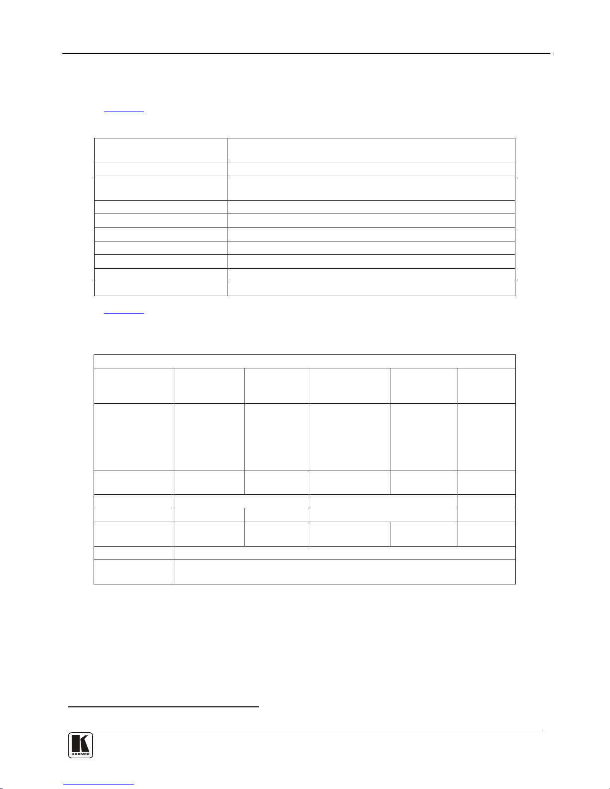
Tables of HEX Codes for Serial Communication (Protocol 2000)
Table 11 lists the Protocol 2000
1
Table 11: Hex Table (IN 1-32 to OUT 1-16)
hex codes for switching inputs 1 to 32 to outputs
1 to 16.
OUT
16
OUT
15
OUT
14
OUT
13
OUT
12
OUT
11
OUT
10
OUT
9
OUT
8
OUT
7
OUT
6
OUT
5
OUT
4
OUT
3
OUT
2
OUT
1
01
81
90
81
01
81
8F
81
01
81
8E
81
01
81
8D
81
01
81
8C
81
01
81
8B
81
01
81
8A
81
01
81
89
81
01
81
88
81
01
81
87
81
01
81
86
81
01
81
85
81
01
81
84
81
01
81
83
81
01
81
82
81
01
81
81
81
IN
1
01
82
90
81
01
82
8F
81
01
82
8E
81
01
82
8D
81
01
82
8C
81
01
82
8B
81
01
82
8A
81
01
82
89
81
01
82
88
81
01
82
87
81
01
82
86
81
01
82
85
81
01
82
84
81
01
82
83
81
01
82
82
81
01
82
81
81
IN
2
01
83
90
81
01
83
8F
81
01
83
8E
81
01
83
8D
81
01
83
8C
81
01
83
8B
81
01
83
8A
81
01
83
89
81
01
83
88
81
01
83
87
81
01
83
86
81
01
83
85
81
01
83
84
81
01
83
83
81
01
83
82
81
01
83
81
81
IN
3
01
84
90
81
01
84
8F
81
01
84
8E
81
01
84
8D
81
01
84
8C
81
01
84
8B
81
01
84
8A
81
01
84
89
81
01
84
88
81
01
84
87
81
01
84
86
81
01
84
85
81
01
84
84
81
01
84
83
81
01
84
82
81
01
84
81
81
IN
4
01
85
90
81
01
85
8F
81
01
85
8E
81
01
85
8D
81
01
85
8C
81
01
85
8B
81
01
85
8A
81
01
85
89
81
01
85
88
81
01
85
87
81
01
85
86
81
01
85
85
81
01
85
84
81
01
85
83
81
01
85
82
81
01
85
81
81
IN
5
01
86
90
81
01
86
8F
81
01
86
8E
81
01
86
8D
81
01
86
8C
81
01
86
8B
81
01
86
8A
81
01
86
89
81
01
86
88
81
01
86
87
81
01
86
86
81
01
86
85
81
01
86
84
81
01
86
83
81
01
86
82
81
01
86
81
81
IN
6
1 Full details are available on our Web site at http://www.kramerelectronics.com
Page 46

KRAMER: SIMPLE CREATIVE TECHNOLOGY
Communication Protocols
42
OUT
16
OUT
15
OUT
14
OUT
13
OUT
12
OUT
11
OUT
10
OUT
9
OUT
8
OUT
7
OUT
6
OUT
5
OUT
4
OUT
3
OUT
2
OUT
1
01
87
90
81
01
87
8F
81
01
87
8E
81
01
87
8D
81
01
87
8C
81
01
87
8B
81
01
87
8A
81
01
87
89
81
01
87
88
81
01
87
87
81
01
87
86
81
01
87
85
81
01
87
84
81
01
87
83
81
01
87
82
81
01
87
81
81
IN
7
01
88
90
81
01
88
8F
81
01
88
8E
81
01
88
8D
81
01
88
8C
81
01
88
8B
81
01
88
8A
81
01
88
89
81
01
88
88
81
01
88
87
81
01
88
86
81
01
88
85
81
01
88
84
81
01
88
83
81
01
88
82
81
01
88
81
81
IN
8
01
89
90
81
01
89
8F
81
01
89
8E
81
01
89
8D
81
01
89
8C
81
01
89
8B
81
01
89
8A
81
01
89
89
81
01
89
88
81
01
89
87
81
01
89
86
81
01
89
85
81
01
89
84
81
01
89
83
81
01
89
82
81
01
89
81
81
IN
9
01
8A
90
81
01
8A
8F
81
01
8A
8E
81
01
8A
8D
81
01
8A
8C
81
01
8A
8B
81
01
8A
8A
81
01
8A
89
81
01
8A
88
81
01
8A
87
81
01
8A
86
81
01
8A
85
81
01
8A
84
81
01
8A
83
81
01
8A
82
81
01
8A
81
81
IN
10
01
8B
90
81
01
8B
8F
81
01
8B
8E
81
01
8B
8D
81
01
8B
8C
81
01
8B
8B
81
01
8B
8A
81
01
8B
89
81
01
8B
88
81
01
8B
87
81
01
8B
86
81
01
8B
85
81
01
8B
84
81
01
8B
83
81
01
8B
82
81
01
8B
81
81
IN
11
01
8C
90
81
01
8C
8F
81
01
8C
8E
81
01
8C
8D
81
01
8C
8C
81
01
8C
8B
81
01
8C
8A
81
01
8C
89
81
01
8C
88
81
01
8C
87
81
01
8C
86
81
01
8C
85
81
01
8C
84
81
01
8C
83
81
01
8C
82
81
01
8C
81
81
IN
12
01
8D
90
81
01
8D
8F
81
01
8D
8E
81
01
8D
8D
81
01
8D
8C
81
01
8D
8B
81
01
8D
8A
81
01
8D
89
81
01
8D
88
81
01
8D
87
81
01
8D
86
81
01
8D
85
81
01
8D
84
81
01
8D
83
81
01
8D
82
81
01
8D
81
81
IN
13
01
8E
90
81
01
8E
8F
81
01
8E
8E
81
01
8E
8D
81
01
8E
8C
81
01
8E
8B
81
01
8E
8A
81
01
8E
89
81
01
8E
88
81
01
8E
87
81
01
8E
86
81
01
8E
85
81
01
8E
84
81
01
8E
83
81
01
8E
82
81
01
8E
81
81
IN
14
01
8F
90
81
01
8F
8F
81
01
8F
8E
81
01
8F
8D
81
01
8F
8C
81
01
8F
8B
81
01
8F
8A
81
01
8F
89
81
01
8F
88
81
01
8F
87
81
01
8F
86
81
01
8F
85
81
01
8F
84
81
01
8F
83
81
01
8F
82
81
01
8F
81
81
IN
15
01
90
90
81
01
90
8F
81
01
90
8E
81
01
90
8D
81
01
90
8C
81
01
90
8B
81
01
90
8A
81
01
90
89
81
01
90
88
81
01
90
87
81
01
90
86
81
01
90
85
81
01
90
84
81
01
90
83
81
01
90
82
81
01
90
81
81
IN
16
01
91
90
81
01
91
8F
81
01
91
8E
81
01
91
8D
81
01
91
8C
81
01
91
8B
81
01
91
8A
81
01
91
89
81
01
91
88
81
01
91
87
81
01
91
86
81
01
91
85
81
01
91
84
81
01
91
83
81
01
91
82
81
01
91
81
81
IN
17
01
92
90
81
01
92
8F
81
01
92
8E
81
01
92
8D
81
01
92
8C
81
01
92
8B
81
01
92
8A
81
01
92
89
81
01
92
88
81
01
92
87
81
01
92
86
81
01
92
85
81
01
92
84
81
01
92
83
81
01
92
82
81
01
92
81
81
IN
18
01
93
90
81
01
93
8F
81
01
93
8E
81
01
93
8D
81
01
93
8C
81
01
93
8B
81
01
93
8A
81
01
93
89
81
01
93
88
81
01
93
87
81
01
93
86
81
01
93
85
81
01
93
84
81
01
93
83
81
01
93
82
81
01
93
81
81
IN
19
01
94
90
81
01
94
8F
81
01
94
8E
81
01
94
8D
81
01
94
8C
81
01
94
8B
81
01
94
8A
81
01
94
89
81
01
94
88
81
01
94
87
81
01
94
86
81
01
94
85
81
01
94
84
81
01
94
83
81
01
94
82
81
01
94
81
81
IN
20
01
95
90
81
01
95
8F
81
01
95
8E
81
01
95
8D
81
01
95
8C
81
01
95
8B
81
01
95
8A
81
01
95
89
81
01
95
88
81
01
95
87
81
01
95
86
81
01
95
85
81
01
95
84
81
01
95
83
81
01
95
82
81
01
95
81
81
IN
21
01
96
90
81
01
96
8F
81
01
96
8E
81
01
96
8D
81
01
96
8C
81
01
96
8B
81
01
96
8A
81
01
96
89
81
01
96
88
81
01
96
87
81
01
96
86
81
01
96
85
81
01
96
84
81
01
96
83
81
01
96
82
81
01
96
81
81
IN
22
01
97
90
81
01
97
8F
81
01
97
8E
81
01
97
8D
81
01
97
8C
81
01
97
8B
81
01
97
8A
81
01
97
89
81
01
97
88
81
01
97
87
81
01
97
86
81
01
97
85
81
01
97
84
81
01
97
83
81
01
97
82
81
01
97
81
81
IN
23
Page 47
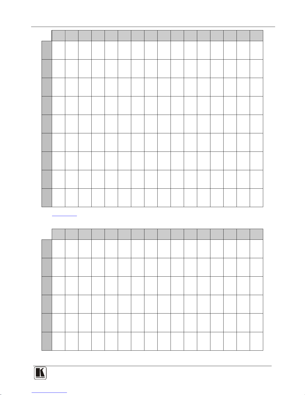
Communication Protocols
43
OUT
16
OUT
15
OUT
14
OUT
13
OUT
12
OUT
11
OUT
10
OUT
9
OUT
8
OUT
7
OUT
6
OUT
5
OUT
4
OUT
3
OUT
2
OUT
1
01
98
90
81
01
98
8F
81
01
98
8E
81
01
98
8D
81
01
98
8C
81
01
98
8B
81
01
98
8A
81
01
98
89
81
01
98
88
81
01
98
87
81
01
98
86
81
01
98
85
81
01
98
84
81
01
98
83
81
01
98
82
81
01
98
81
81
IN
24
01
99
90
81
01
99
8F
81
01
99
8E
81
01
99
8D
81
01
99
8C
81
01
99
8B
81
01
99
8A
81
01
99
89
81
01
99
88
81
01
99
87
81
01
99
86
81
01
99
85
81
01
99
84
81
01
99
83
81
01
99
82
81
01
99
81
81
IN
25
01
9A
90
81
01
9A
8F
81
01
9A
8E
81
01
9A
8D
81
01
9A
8C
81
01
9A
8B
81
01
9A
8A
81
01
9A
89
81
01
9A
88
81
01
9A
87
81
01
9A
86
81
01
9A
85
81
01
9A
84
81
01
9A
83
81
01
9A
82
81
01
9A
81
81
IN
26
01
9B
90
81
01
9B
8F
81
01
9B
8E
81
01
9B
8D
81
01
9B
8C
81
01
9B
8B
81
01
9B
8A
81
01
9B
89
81
01
9B
88
81
01
9B
87
81
01
9B
86
81
01
9B
85
81
01
9B
84
81
01
9B
83
81
01
9B
82
81
01
9B
81
81
IN
27
01
9C
90
81
01
9C
8F
81
01
9C
8E
81
01
9C
8D
81
01
9C
8C
81
01
9C
8B
81
01
9C
8A
81
01
9C
89
81
01
9C
88
81
01
9C
87
81
01
9C
86
81
01
9C
85
81
01
9C
84
81
01
9C
83
81
01
9C
82
81
01
9C
81
81
IN
28
01
9D
90
81
01
9D
8F
81
01
9D
8E
81
01
9D
8D
81
01
9D
8C
81
01
9D
8B
81
01
9D
8A
81
01
9D
89
81
01
9D
88
81
01
9D
87
81
01
9D
86
81
01
9D
85
81
01
9D
84
81
01
9D
83
81
01
9D
82
81
01
9D
81
81
IN
29
01
9E
90
81
01
9E
8F
81
01
9E
8E
81
01
9E
8D
81
01
9E
8C
81
01
9E
8B
81
01
9E
8A
81
01
9E
89
81
01
9E
88
81
01
9E
87
81
01
9E
86
81
01
9E
85
81
01
9E
84
81
01
9E
83
81
01
9E
82
81
01
9E
81
81
IN
30
01
9F
90
81
01
9F
8F
81
01
9F
8E
81
01
9F
8D
81
01
9F
8C
81
01
9F
8B
81
01
9F
8A
81
01
9F
89
81
01
9F
88
81
01
9F
87
81
01
9F
86
81
01
9F
85
81
01
9F
84
81
01
9F
83
81
01
9F
82
81
01
9F
81
81
IN
31
01
A0
90
81
01
A0
8F
81
01
A0
8E
81
01
A0
8D
81
01
A0
8C
81
01
A0
8B
81
01
A0
8A
81
01
A0
89
81
01
A0
88
81
01
A0
87
81
01
A0
86
81
01
A0
85
81
01
A0
84
81
01
A0
83
81
01
A0
82
81
01
A0
81
81
IN
32
UTable 12 Ulists the hex codes for switching inputs 1 to 32 to outputs 17 to 32.
Table 12: Hex Table (IN 1-32 to OUT 17-32)
OUT
32
OUT
31
OUT
30
OUT
29
OUT
28
OUT
27
OUT
26
OUT
25
OUT
24
OUT
23
OUT
22
OUT
21
OUT
20
OUT
19
OUT
18
OUT
17
01
81
A0
81
01
81
9F
81
01
81
9E
81
01
81
9D
81
01
81
9C
81
01
81
9B
81
01
81
9A
81
01
81
99
81
01
81
98
81
01
81
97
81
01
81
96
81
01
81
95
81
01
81
94
81
01
81
93
81
01
81
92
81
01
81
91
81
IN
1
01
82
A0
81
01
82
9F
81
01
82
9E
81
01
82
9D
81
01
82
9C
81
01
82
9B
81
01
82
9A
81
01
82
99
81
01
82
98
81
01
82
97
81
01
82
96
81
01
82
95
81
01
82
94
81
01
82
93
81
01
82
92
81
01
82
91
81
IN
2
01
83
A0
81
01
83
9F
81
01
83
9E
81
01
83
9D
81
01
83
9C
81
01
83
9B
81
01
83
9A
81
01
83
99
81
01
83
98
81
01
83
97
81
01
83
96
81
01
83
95
81
01
83
94
81
01
83
93
81
01
83
92
81
01
83
91
81
IN
3
01
84
A0
81
01
84
9F
81
01
84
9E
81
01
84
9D
81
01
84
9C
81
01
84
9B
81
01
84
9A
81
01
84
99
81
01
84
98
81
01
84
97
81
01
84
96
81
01
84
95
81
01
84
94
81
01
84
93
81
01
84
92
81
01
84
91
81
IN
4
01
85
A0
81
01
85
9F
81
01
85
9E
81
01
85
9D
81
01
85
9C
81
01
85
9B
81
01
85
9A
81
01
85
99
81
01
85
98
81
01
85
97
81
01
85
96
81
01
85
95
81
01
85
94
81
01
85
93
81
01
85
92
81
01
85
91
81
IN
5
01
86
A0
81
01
86
9F
81
01
86
9E
81
01
86
9D
81
01
86
9C
81
01
86
9B
81
01
86
9A
81
01
86
99
81
01
86
98
81
01
86
97
81
01
86
96
81
01
86
95
81
01
86
94
81
01
86
93
81
01
86
92
81
01
86
91
81
IN
6
Page 48

KRAMER: SIMPLE CREATIVE TECHNOLOGY
Communication Protocols
44
OUT
32
OUT
31
OUT
30
OUT
29
OUT
28
OUT
27
OUT
26
OUT
25
OUT
24
OUT
23
OUT
22
OUT
21
OUT
20
OUT
19
OUT
18
OUT
17
01
87
A0
81
01
87
9F
81
01
87
9E
81
01
87
9D
81
01
87
9C
81
01
87
9B
81
01
87
9A
81
01
87
99
81
01
87
98
81
01
87
97
81
01
87
96
81
01
87
95
81
01
87
94
81
01
87
93
81
01
87
92
81
01
87
91
81
IN
7
01
88
A0
81
01
88
9F
81
01
88
9E
81
01
88
9D
81
01
88
9C
81
01
88
9B
81
01
88
9A
81
01
88
99
81
01
88
98
81
01
88
97
81
01
88
96
81
01
88
95
81
01
88
94
81
01
88
93
81
01
88
92
81
01
88
91
81
IN
8
01
89
A0
81
01
89
9F
81
01
89
9E
81
01
89
9D
81
01
89
9C
81
01
89
9B
81
01
89
9A
81
01
89
99
81
01
89
98
81
01
89
97
81
01
89
96
81
01
89
95
81
01
89
94
81
01
89
93
81
01
89
92
81
01
89
91
81
IN
9
01
8A
A0
81
01
8A
9F
81
01
8A
9E
81
01
8A
9D
81
01
8A
9C
81
01
8A
9B
81
01
8A
9A
81
01
8A
99
81
01
8A
98
81
01
8A
97
81
01
8A
96
81
01
8A
95
81
01
8A
94
81
01
8A
93
81
01
8A
92
81
01
8A
91
81
IN
10
01
8B
A0
81
01
8B
9F
81
01
8B
9E
81
01
8B
9D
81
01
8B
9C
81
01
8B
9B
81
01
8B
9A
81
01
8B
99
81
01
8B
98
81
01
8B
97
81
01
8B
96
81
01
8B
95
81
01
8B
94
81
01
8B
93
81
01
8B
92
81
01
8B
91
81
IN
11
01
8C
A0
81
01
8C
9F
81
01
8C
9E
81
01
8C
9D
81
01
8C
9C
81
01
8C
9B
81
01
8C
9A
81
01
8C
99
81
01
8C
98
81
01
8C
97
81
01
8C
96
81
01
8C
95
81
01
8C
94
81
01
8C
93
81
01
8C
92
81
01
8C
91
81
IN
12
01
8D
A0
81
01
8D
9F
81
01
8D
9E
81
01
8D
9D
81
01
8D
9C
81
01
8D
9B
81
01
8D
9A
81
01
8D
99
81
01
8D
98
81
01
8D
97
81
01
8D
96
81
01
8D
95
81
01
8D
94
81
01
8D
93
81
01
8D
92
81
01
8D
91
81
IN
13
01
8E
A0
81
01
8E
9F
81
01
8E
9E
81
01
8E
9D
81
01
8E
9C
81
01
8E
9B
81
01
8E
9A
81
01
8E
99
81
01
8E
98
81
01
8E
97
81
01
8E
96
81
01
8E
95
81
01
8E
94
81
01
8E
93
81
01
8E
92
81
01
8E
91
81
IN
14
01
8F
A0
81
01
8F
9F
81
01
8F
9E
81
01
8F
9D
81
01
8F
9C
81
01
8F
9B
81
01
8F
9A
81
01
8F
99
81
01
8F
98
81
01
8F
97
81
01
8F
96
81
01
8F
95
81
01
8F
94
81
01
8F
93
81
01
8F
92
81
01
8F
91
81
IN
15
01
90
A0
81
01
90
9F
81
01
90
9E
81
01
90
9D
81
01
90
9C
81
01
90
9B
81
01
90
9A
81
01
90
99
81
01
90
98
81
01
90
97
81
01
90
96
81
01
90
95
81
01
90
94
81
01
90
93
81
01
90
92
81
01
90
91
81
IN
16
01
91
A0
81
01
91
9F
81
01
91
9E
81
01
91
9D
81
01
91
9C
81
01
91
9B
81
01
91
9A
81
01
91
99
81
01
91
98
81
01
91
97
81
01
91
96
81
01
91
95
81
01
91
94
81
01
91
93
81
01
91
92
81
01
91
91
81
IN
17
01
92
A0
81
01
92
9F
81
01
92
9E
81
01
92
9D
81
01
92
9C
81
01
92
9B
81
01
92
9A
81
01
92
99
81
01
92
98
81
01
92
97
81
01
92
96
81
01
92
95
81
01
92
94
81
01
92
93
81
01
92
92
81
01
92
91
81
IN
18
01
93
A0
81
01
93
9F
81
01
93
9E
81
01
93
9D
81
01
93
9C
81
01
93
9B
81
01
93
9A
81
01
93
99
81
01
93
98
81
01
93
97
81
01
93
96
81
01
93
95
81
01
93
94
81
01
93
93
81
01
93
92
81
01
93
91
81
IN
19
01
94
A0
81
01
94
9F
81
01
94
9E
81
01
94
9D
81
01
94
9C
81
01
94
9B
81
01
94
9A
81
01
94
99
81
01
94
98
81
01
94
97
81
01
94
96
81
01
94
95
81
01
94
94
81
01
94
93
81
01
94
92
81
01
94
91
81
IN
20
01
95
A0
81
01
95
9F
81
01
95
9E
81
01
95
9D
81
01
95
9C
81
01
95
9B
81
01
95
9A
81
01
95
99
81
01
95
98
81
01
95
97
81
01
95
96
81
01
95
95
81
01
95
94
81
01
95
93
81
01
95
92
81
01
95
91
81
IN
21
01
96
A0
81
01
96
9F
81
01
96
9E
81
01
96
9D
81
01
96
9C
81
01
96
9B
81
01
96
9A
81
01
96
99
81
01
96
98
81
01
96
97
81
01
96
96
81
01
96
95
81
01
96
94
81
01
96
93
81
01
96
92
81
01
96
91
81
IN
22
01
97
A0
81
01
97
9F
81
01
97
9E
81
01
97
9D
81
01
97
9C
81
01
97
9B
81
01
97
9A
81
01
97
99
81
01
97
98
81
01
97
97
81
01
97
96
81
01
97
95
81
01
97
94
81
01
97
93
81
01
97
92
81
01
97
91
81
IN
23
Page 49

Communication Protocols
45
OUT
32
OUT
31
OUT
30
OUT
29
OUT
28
OUT
27
OUT
26
OUT
25
OUT
24
OUT
23
OUT
22
OUT
21
OUT
20
OUT
19
OUT
18
OUT
17
01
98
A0
81
01
98
9F
81
01
98
9E
81
01
98
9D
81
01
98
9C
81
01
98
9B
81
01
98
9A
81
01
98
99
81
01
98
98
81
01
98
97
81
01
98
96
81
01
98
95
81
01
98
94
81
01
98
93
81
01
98
92
81
01
98
91
81
IN
24
01
99
A0
81
01
99
9F
81
01
99
9E
81
01
99
9D
81
01
99
9C
81
01
99
9B
81
01
99
9A
81
01
99
99
81
01
99
98
81
01
99
97
81
01
99
96
81
01
99
95
81
01
99
94
81
01
99
93
81
01
99
92
81
01
99
91
81
IN
25
01
9A
A0
81
01
9A
9F
81
01
9A
9E
81
01
9A
9D
81
01
9A
9C
81
01
9A
9B
81
01
9A
9A
81
01
9A
99
81
01
9A
98
81
01
9A
97
81
01
9A
96
81
01
9A
95
81
01
9A
94
81
01
9A
93
81
01
9A
92
81
01
9A
91
81
IN
26
01
9B
A0
81
01
9B
9F
81
01
9B
9E
81
01
9B
9D
81
01
9B
9C
81
01
9B
9B
81
01
9B
9A
81
01
9B
99
81
01
9B
98
81
01
9B
97
81
01
9B
96
81
01
9B
95
81
01
9B
94
81
01
9B
93
81
01
9B
92
81
01
9B
91
81
IN
27
01
9C
A0
81
01
9C
9F
81
01
9C
9E
81
01
9C
9D
81
01
9C
9C
81
01
9C
9B
81
01
9C
9A
81
01
9C
99
81
01
9C
98
81
01
9C
97
81
01
9C
96
81
01
9C
95
81
01
9C
94
81
01
9C
93
81
01
9C
92
81
01
9C
91
81
IN
28
01
9D
A0
81
01
9D
9F
81
01
9D
9E
81
01
9D
9D
81
01
9D
9C
81
01
9D
9B
81
01
9D
9A
81
01
9D
99
81
01
9D
98
81
01
9D
97
81
01
9D
96
81
01
9D
95
81
01
9D
94
81
01
9D
93
81
01
9D
92
81
01
9D
91
81
IN
29
01
9E
A0
81
01
9E
9F
81
01
9E
9E
81
01
9E
9D
81
01
9E
9C
81
01
9E
9B
81
01
9E
9A
81
01
9E
99
81
01
9E
98
81
01
9E
97
81
01
9E
96
81
01
9E
95
81
01
9E
94
81
01
9E
93
81
01
9E
92
81
01
9E
91
81
IN
30
01
9F
A0
81
01
9F
9F
81
01
9F
9E
81
01
9F
9D
81
01
9F
9C
81
01
9F
9B
81
01
9F
9A
81
01
9F
99
81
01
9F
98
81
01
9F
97
81
01
9F
96
81
01
9F
95
81
01
9F
94
81
01
9F
93
81
01
9F
92
81
01
9F
91
81
IN
31
01
A0
A0
81
01
A0
9F
81
01
A0
9E
81
01
A0
9D
81
01
A0
9C
81
01
A0
9B
81
01
A0
9A
81
01
A0
99
81
01
A0
98
81
01
A0
97
81
01
A0
96
81
01
A0
95
81
01
A0
94
81
01
A0
93
81
01
A0
92
81
01
A0
91
81
IN
32
Page 50

KRAMER: SIMPLE CREATIVE TECHNOLOGY
46
LIMITED WARRANTY
WHO IS PROTECTED?
WHAT IS COVERED AND WHAT IS NOT COVERED
WHAT WE WILL PAY FOR AND WHAT WE WILL NOT PAY FOR
HOW YOU CAN GET WARRANTY SERVICE
LIMITATION OF IMPLIE D WARRANTIES
EXCLUSION OF DAMAGES
CAUTION!
We warrant this product free from defects in material and workmanship under the following terms.
HOW LONG IS THE WARRANTY
Labor and parts are warranted for three years from the date of the first customer purchase.
Only the first purchase customer may enforce this warranty.
We will pay labor and material expenses for covered items. We will not pay for the following:
The liability of Kramer for any effective products is limited to the repair or replacement of the product at our option. Kramer
shall not be lia ble for:
This warranty gives you specific legal rights, and you may also have other rights, which vary from place to place.
: All products returned to Kramer for service must hav e prior approval. This may be obt ained from your dealer.
This equipment has been tested to determine compliance with the requirements of:
EN-50081: "Electromagnetic com patibility (EMC);
generic emission standard.
R esidential, commercial and light indu stry"
EN-50082: "Electromagnetic compatibility (EMC) generic immunity standard.
Part 1: Resid ential, commercial and light industry environment".
CFR-47: FCC* Rules and Regulations:
Part 15: “Radio frequency devices
Subpart B Unintentional radiators”
Except as below, this warranty covers all defects in material or workmanship in this product. The following are not
covered by the warranty:
1. Any product which is not distributed by us or which is not purchased from an authorized Kramer dealer. If you are
uncertain as to whether a dealer is authorized, please contact Kramer at one of the agents listed in the Web site
www.kramerelectronics.com.
2. Any product, on which the serial number has been defaced, modified or removed, or on which the WARRANTY VOID
TAMPERED sticker has been torn,
3. Damage, deteriora tion or malfunction resulting from:
i) Accident, mis use, abuse, neglect, fire, water, lightning o r other acts of nature
ii) P roduct modification, or failure to follow instructions supplied with the product
iii) Repair or attempted repair by anyone not authorized by Kramer
iv) Any shipment of the prod uct (claims must be presented t o the carrier)
v) Removal or in stallation of the product
vi) Any other cause, which does not relate to a prod uct defect
vii) Cartons, equi pment enclosures, cables or acces sories used in conjunction with t he product
1. Removal or installations charges.
2. Costs of initial technical adjustments (set-up), including adjustment of user controls or programming. These costs are
the responsibility of the Kramer dealer from w hom the product was purch ased.
3. Shipping charges.
1. To obtain service on you product, you must take or ship it prepaid to any authorized Kramer service center.
2. Whenever warranty service is required, the original dated invoice (or a copy) must be presented as proof of
warranty coverage, and should be included in any shipment of the product. Please also include in any mailing a
contact name, company, address, and a description of the problem(s).
3. For the name of the nearest Kramer authorized service center, consult your a uthorized dealer.
All implied warranties, including warranties of merchantability and fitness for a particular purpose, are limited in duration
to the length of this warranty.
1. Damage to other property caused by defects in this product, damages based upon inconvenience, loss of use of the
product, loss of time, commercial loss; or:
2. Any other damages, whether incidental, consequential or otherwise. Some countries may not allow limitations on
how long an implied warranty lasts and/or do not allow the exclusion or limitation of incidental or consequential
damages, so the above limitations and exclusions may not apply to you.
Servicing the machines can only be done by an authorized Kramer technician. Any user who makes changes or
modifications to the unit without the expressed approval of the manufacturer will void user authority to operate the
equipment.
Use the supplied DC power supply to feed power to the machine.
Please use recom mended interconnection cables to c onnect the machine to othe r components.
IF reattached, removed or otherwise interfered with.
* FCC and C E approved using ST P cable ( for twisted pair produ cts)
NOTE
Part 1:
Page 51

Kramer Electronics, Ltd.
Web site: www.kramerelectronics.com
E-mail: info@kramerel.com
P/N: 2900-300014 REV 2
For the latest information on our products and a list of
Kramer distributors visit
www.kramerelectronics.com
where updates to this user manual may be found.
We welcome your questions, comments and feedback.
Safety Warning:
Disconnect the unit from the power supply
before opening/servicing.
Caution
PN:
2900- 300014
Rev:
2
 Loading...