

Page 1

Kramer Electronics, Ltd.
USER MANUAL
Model:
VS-28
8 Channel Video Audio Standby
Page 2

Contents
i
Contents
1 Introduction 1
2 Getting Started 1
3 Overview 2
3.1 Several Words on Video/Audio Switchers 2
4 Your 8 Channel Video Audio Standby 4
4.1 Your 8 Channel Video Audio Standby Front Panel 4
4.2 Your 8 Channel Video Audio Standby Rear Panel 4
5 Using Your 8 Channel Video Audio Standby 5
6 Technical Specifications 6
Figures
Figure 1: VS-28 8 Channel Video Audio Standby Front Panel 4
Figure 2: VS-28 8 Channel Video Audio Standby Rear Panel 4
Tables
Table 1: Technical Specifications of the VS-28 8 Channel Video Audio Standby 6
Page 3

Introduction
1
1 Introduction
Welcome to Kramer Electronics (since 1981): a world of unique, creative and
affordable solutions to the infinite range of problems that confront the video,
audio and presentation professional on a daily basis. In recent years, we have
redesigned and upgraded most of our line, making the best even better! Our
350-plus different models now appear in 8 Groups
1
, which are clearly defined
by function.
Congratulations on purchasing your Kramer VS-28 8 Channel Video Audio
Standby, which is ideal for the following typical applications:
• Broadcast applications to eliminate dead air time
• Security applications for automatic switching of control cameras
• Presentation systems for automatic detection of active wall plate inputs
• Point-of-sale systems requiring uninterrupted demonstrations and
advertising
The package includes the following items:
• VS-28 8 Channel Video Audio Standby
• Power cord
• This user manual
2
and the Kramer concise product catalog/CD
2 Getting Started
We recommend that you:
• Unpack the equipment carefully and save the original box and packaging
materials for possible future shipment
• Review the contents of this user manual
• Use Kramer high performance high resolution cables
3
1 GROUP 1: Distribution Amplifiers; GROUP 2: Video and Audio Switchers, Matrix Switchers and Controllers; GROUP 3 :
Video, Audio, VGA/XGA Processors; GROUP 4: Interfaces and Sync Processors; GROUP 5: Twisted Pair Interfaces;
GROUP 6: Accessories and Rack Adapters; GROUP 7: Scan Converters and Scalers; and GROUP 8: Cables and Connectors
2 Download up-to-date Kramer user manuals from the Internet at this URL: http://www.kramerelectronics.com/manuals.html
3 The complete list of Kramer cables is on our Web site at http://www.kramerelectronics.com (click “Cables and Connectors ”
in the Products section)
Page 4

KRAMER: SIMPLE CREATIVE TECHNOLOGY
Overview
2
3 Overview
The VS-28 8 Channel Video Audio Standby is an eight channel standby
switcher for composite video and stereo audio signals. Each of the eight
channels is a discreet 2x1 standby switcher for composite video using BNC
connectors, and stereo audio using detachable screw terminal connectors.
The VS-28 8 Channel Video Audio Standby is much like having eight Kramer
VS-24N’s in a single two-space rack mountable enclosure. Each 2x1 channel
is designed to automatically switch to the second input any time the primary
video signal is interrupted. At the same time, a front-panel LED illu mi nates,
and an extra relay is activated which can be used to trigger an alarm. If the
primary signal reappears, the individual channel will switch back to input
one. Each channel can be forced to select input 2 by using a short to ground
available on detachable screw terminal connectors. When the power of the
VS-28 8 Channel Video Audio Standby is removed or turned off, input one
will be routed to the output.
Achieving the best performance means:
• Connecting only good quality connection cables, thus avoiding
interference, deterioration in signal quality due to poor matching, and elevated
noise levels (often associated with low quality cables)
• Avoiding interference from neighboring electrical appliances and
positioning your VS-28 away from excessive sunlight, moisture and dust
3.1 Several Words on Video/Audio Switchers
A video/audio switcher usually switches between several sources and one or
more acceptors. A switcher that allows several inputs to be connected to
several outputs simultaneously is called a matrix switcher. Switchers may be
of the electronic or mechanic type. Most matrices are of the active electronic
type, with many crosspoints.
Vertical Interval Switching, often used in video, assures that the transition
from one video source to the other (like switching between two Genlocked
cameras) is smooth and without interference. The switching and changeover
is done during the blanked vertical interval period, where the transition is
hidden from the eyes.
Vertical Interval switching is needed when recording or transmitting a video
program involving several video sour ces, as in li ve broad cast, to assure
“clean”, undisturbed picture transitions. The switched sources should be
genlocked.
Matrices and switchers may be RS-232 controlled. RS-232 control is a way of
remotely controlling a video or audio device using a personal computer with a
Page 5

Overview
3
serial port or another device that uses a similar communication protocol.
The simplest connection between the RS-232 controller and the controlled
device uses two wires (TRANSMIT, RECEIVE) and a common ground wire.
Adding inputs, outputs or both may extend a matrix switcher. In order to add
OUTPUTS to a matrix setup, a second switcher is added, and the inputs of
both matrices are connected in parallel (while assuring proper input
termination and avoiding double termination).
In order to add INPUTS to an existing matrix, a second machine is connected
- paralleling the outputs of both machines. When a matrix is to be extended in
both directions, both INPUTS and OUTPUTS are paralleled using four or
more machines. A matrix can be extended only if it is designed as an
extendable matrix, e.g., inputs should be looping and outputs should be able
to be internally disconnected or become “floating”.
There are many factors affecting quality when signals are transmitted from a
source to an acceptor:
• Source and acceptor signal handling capability - different brands offer
different quality and the final result is determined by the performance of the
lowest quality part. Using a low quality source will always result in low
quality duplicates
• The connection cables should be of the best possible quality. Low quality
cables are susceptible to interference, deteriorate signal quality due to poor
matching and cause elevated noise levels
• Sockets and connectors of the sources and acceptors - so often ignored,
should be of best quality, as "Zero Ohm" connection resistance should be
assured. Sockets and connectors should match the required impedance (75
ohms in video). Cheap connectors tend to rust, causing breaks in the signal
path
• Amplifying circuitry quality is extremely important and is needed for
high linearity, low distortion and low noise operation
• The distance between source and acceptors plays a major role in the final
result. If there are long distances (over 15 meters) between sources and
acceptors, special means should be taken in order to avoid cable loss, such as
using higher quality cables or, if necessary, adding line amplifiers
• Interference from neighboring appliances may have an adverse effect on
signal quality. Balanced audio lines are less prone to interference, but
unbalanced audio and video lines should be installed far away from mains
carrying cables, electric motors, transmitters etc., even when cables are
shielded
Page 6
KRAMER: SIMPLE CREATIVE TECHNOLOGY
Your 8 Channel Video Audio Standby
4
4 Your 8 Channel Video Audio Standby
The VS-28 8 Channel Video Audio Standby is an 8 Channel Video-Audio
Standby unit, each channel having two video and audio-stereo (or balanced
Mono) inputs and one video and audio-stereo (or balanced Mono) output.
When a proper video signal exists on the input marked INPUT 1, it is
transferred, with the appropriate audio channels, to the output. When the
video signal drops for any reason, the VS-28 8 Channel Video Audio Standby
automatically routes the second video-audio source to the output and at the
same time activates a relay (alarm) and lights a LED on the front panel. When
the video signal on INPUT 1 reappears, the unit switches back to it
automatically. When the power is off, INPUT 1 is routed to the output. The
machine can be forced to output the INPUT 2 signal by using a short to
ground, where each channel can be remote controlled with a pair of wires.
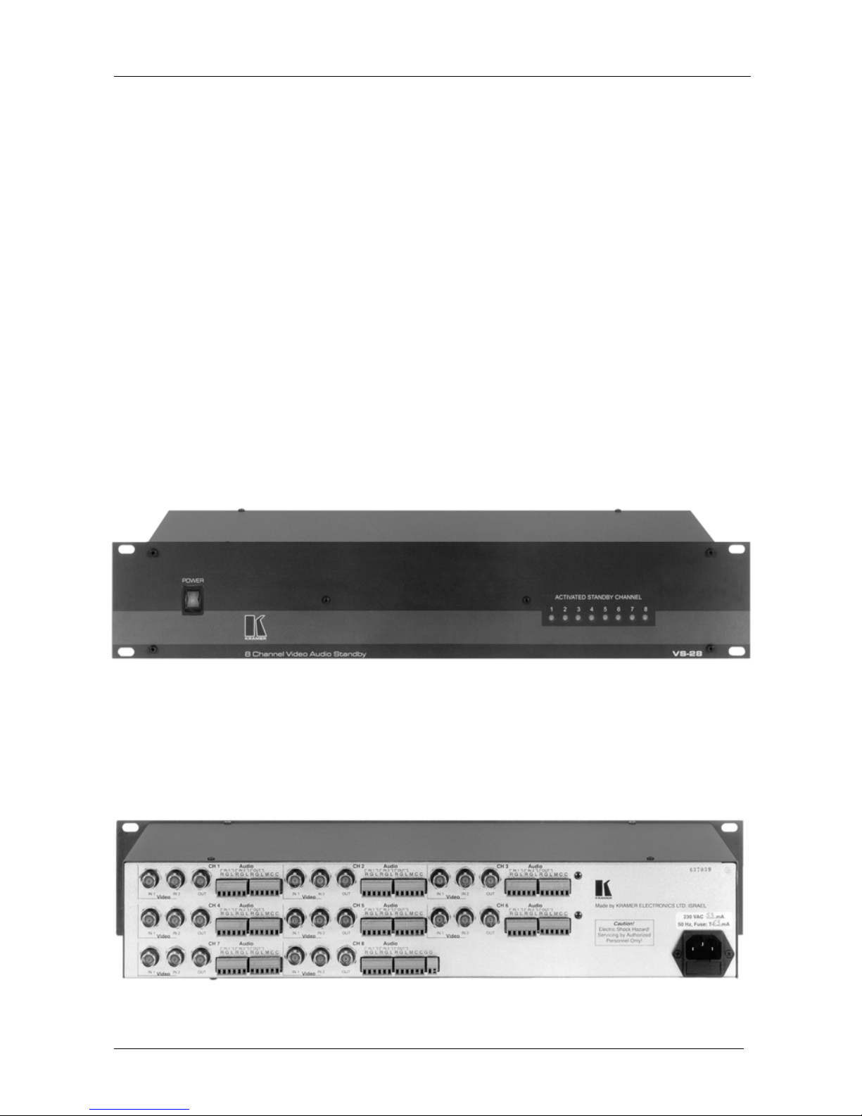
4.1 Your 8 Channel Video Audio Standby Front Panel
Figure 1 illustrates the front panel of the VS-28 8 Channel Video Audio
Standby:
Figure 1: VS-28 8 Channel Video Audio Standby Front Panel
4.2 Your 8 Channel Video Audio Standby Rear Panel
Figure 2 illustrates the rear panel of the VS-28 8 Channel Video Audio
Standby:
Figure 2: VS-28 8 Channel Video Audio Standby Rear Panel
Page 7

Using Your 8 Channel Video Audio Standby
5
5 Using Your 8 Channel Video Audio Standby
This section describes how to connect and operate your 8 Channel Video
Audio Standby.
Connect the video and audio sources to the appropriate inputs of the VS-28 8
Channel Video Audio Standby unit, where input 1 of each channel is the
Master input, and input 2 is the standby channel. Be sure to connect the audio
channels with the correct polarities.
You can either use the audio as Left, Ground and Right signals (for stereo) or
use the "R" for "+" and the "L" for "-" for balanced mono.
Connect up to 8 video/audio acceptors to output sockets. Use the best cables
available in order not to impair signal quality and bandwidth.
Each channel has two pins (on the audio connector) each marked as "C".
When the main signal (IN 1) of this channel drops, an internal rela y shorts
both pins to each other. This can be used, for example, to activate an alarm.
Each channel has an additional pin on the "audio block" marked " M". When
this pin is remotely connected to the ground (using a pair of wires) this
channel is forced to switchover to input 2.
When the master video (IN 1) drops out of any channel, the machine switches
over to the standby input (IN 2) of this channel. At the same time, it activates
the internal relay that shorts together the pins marked "C" on the audio
connector and lights an LED with of appropriate channel number on the front
panel.
There are two extra ground connections available on the audio section of
channel 8 for any desired use. The connections are each marked "G".
Turn on the VS-28 8 Channel Video Audio Standby and all sources and
acceptors. The VS-28 8 Channel Video Audio Standby detects the existence
of Odd/Even sync information; therefore it cannot be misled by erroneous
signals. If all master video inputs are available and are standard video signals,
all front LEDs will be off.
By using the remote control function with the "M" pin mentioned above, t he
VS-28 8 Channel Video Audio Standby can become an 8x2x1 video/audio
switcher.
The channels may be cascaded to increase the number of standby sources, for
example: connect the output of channel 1 to IN1 of channel 2 and connect the
acceptor to the OUT socket of channel 2. In this case, if IN 1 of channel 1
drops out, IN 2 of channel 1 "kicks" in. If IN 2 of channel one drops out too
(and IN 1 is still absent) IN 2 of channel 2 "kicks in", etc.
Page 8
KRAMER: SIMPLE CREATIVE TECHNOLOGY
Technical Specifications
6
6 Technical Specifications
Table 1 includes the technical specifications.
Table 1: Technical Specifications1 of the VS-28 8 Channel Video Audio Standby
INPUTS:
8 x 2 composite video, 1Vpp/75Ω nom. on BNC connectors
8 x 2 audio stereo (or balanced Mono) on terminal blocks
OUTPUTS: 8 x 1 remote control pin (for short to ground)
8 x 1 composite video, 1Vpp/75Ω on a BNC connector
8 x 1 audio stereo (or balanced Mono) on terminal blocks
8 x rela y contacts
VIDEO BANDWIDTH: Up to 500MHz
AUDIO BANDWIDTH: Up to 100MHz
S/N RATIO: 73dB
DETECTION SYSTEM: Odd/Even fields
SWITCH DELAY: Up to 3 frames
CONTROL: Contact closure, automatic
DIMENSIONS: 19 inch (W), 7 inch (D), 2U (H) rack mountable
POWER: 230 VAC, 50/60Hz (115 VAC U.S.A.) 12.2 VA
WEIGHT: 3.8kg (8.4lbs.) approx.
ACCESSORIES: Power cord
If the output signal is disturbed or interrupted by very strong external
electromagnetic interference, it should return and stabilize when such
interference ends. If not, turn the power switch off and on again to reset the
machine. The socket-outlet shall be installed near the equipment and shall be
easily accessible. To fully disconnect the equipment, remove the power cord
from its socket .
1 Specifications are subject to change without notice
Page 9

7
LIMITED WARRANTY
Kramer Electronics (hereafter Kramer) warrants this product free from defects in material and workmanship under the
following terms.
HOW LONG IS THE WARRANTY
Labor and parts are warranted for three years from the date of the first customer purchase.
WHO IS PROTECTED?
Only the first purchase customer may enforce this warranty.
WHAT IS COVERED AND WHAT IS NOT COVERED
Except as below, this warranty covers all defects in material or workmanship in this product. The following are not covered
by the warranty:
1. Any product which is not distributed by Kramer, or which is not purchased from an authorized Kramer dealer. If you are
uncertain as to whether a dealer is authorized, please contact Kramer at one of the agents listed in the web site
www.kramerelectronics.com.
2. Any product, on which the serial number has been defaced, modified or removed.
3. Dama ge, deteriora tion o r malfu nctio n resulting fro m:
i) Accident, misuse, abuse, neglect, fire, water, lightning or other acts of nature
ii) Product modification, or failure to follow instructions supplied with the product
iii) Repair or attempted repair by anyone not authorized by Kramer
iv) Any shipment of the product (claims must be presented to the carrier)
v) Re moval or insta llation of the product
vi) Any other c ause, which does not relate to a pr oduct defec t
vii) Cartons, equipment enclosures, cables or accessories used in conjunction with the product
WHAT WE WILL PAY FOR AND WHAT WE WILL NOT PAY FOR
We will pay labor and material expenses for covered items. We will not pay for the following:
1. Removal or installations charges.
2. Costs of initial technical adjustments (set-up), including adjustment of user controls or programming. These costs are the
responsibility of the Kramer dealer from whom the product was pur chased.
3. Shipping charges.
HOW YOU CAN GET WARRANTY SERVICE
1. To obtain service on you product, you must take or ship it prepaid to any authorized Kramer service center.
2. Whenever warranty service is required, t he origina l dated invoice (or a copy) must be presented as proof of warrant y coverage,
and should be included in any shipment of the product. Please also include in any mailing a contact name, company, address, and
a description of the problem(s).
3. For the name of the nearest Kramer authorized service center, co nsult your autho r ized dealer.
LIMITATION OF IMPLIED WARRANTIES
All implied warranties, including warranties of merchantability and fitness for a particular purpose, are limited in duration to
the length of this warranty.
EXCLUSION OF DAMAGES
The liability of Kramer for any effective products is li mited to the repair or replace ment of t he product at our option. Kramer
shall not be liable for:
1. Damage to other property caused by defects in this pro duct, da mages based upon inconve nience, loss of use of the product, loss
of time, commercial loss; or:
2. Any ot her d amag es, w het her incid ent al, c ons eque nt ial o r ot herw ise. S o me co unt ries may no t allow limit at ions o n ho w long a n
implied warranty lasts and/or do not allow the exclusion or limitat ion of incidental or consequential damages, so t he above
limitations and exclusions may not apply to you.
This warranty gives you specific legal rights, and you may also have other rights, which vary from place to place.
NOTE: All products returned to Kramer for service must have prior approval. This may be obtained from your dealer.
This equipment has been tested to determine compliance with the requirements of:
EN-50081: "Electromagnetic compatibility (EMC);
generic emission standard.
Part 1: Residential, commercial and light industry"
EN-50082: "Electromagnetic compatibility (EMC) generic immunity standard.
Part 1: Residential, commercial and light industry environment".
CFR-47: FCC Rules and Regulations:
Part 15: “Radio frequency devices
Subpart B – Unintentional radiators”
CAUTION!
⌦ Servicing the machines can only be done by an authorized Kramer technician. Any user who makes changes or modifications to
the unit without the expressed approval of the manufacturer will void user author it y to operat e the equipment.
⌦ Use the supplied DC power supply to feed power to the machine.
⌦ Please use recommended interconnection cables to co nnect the machine to ot her components.
Page 10

Kramer Electronics, Ltd.
3 Am VeOlamo Street. Jerusalem 95463, Israel Tel: (+972-2)-654-4000
Fax: (+972-2)-653-5369, E-mail: [email protected]
P/N: JUST PDF VS-28 REV 1
For the latest information on our products and a list of Kramer
distributors, visit our Web site: www.kramerelectronics.com.
Updates to this user manual may be found at
http://www.kramerelectronics.com/manuals.html.
We welcome your questions, comments and feedback.
 Loading...