

Page 1

Kramer Electronics, Ltd.
Preliminary
USER MANUAL
Model:
VS-169TP
16x9 CAT 5 Matrix Switcher
Page 2

Contents
i
Contents
1 Introduction 1
2 Getting Started 1
2.1 Achieving the Best Performance 2
2.2 Safety Instructions 2
2.3 Recycling Kramer Products 2
2.4 Quick Start 3
3 Overview 4
3.1 Shielded Twisted Pair (STP) / Unshielded Twisted Pair (UTP) 5
4 Your VS-169TP 16x9 CAT 5 Matrix Switcher 5
4.1 Using the IR Transmitter 10
5 Installing the VS-169TP in a Rack 11
5.1 Wiring the CAT 5 LINE IN / LINE OUT RJ-45 Connectors 12
6 Connecting the VS-169TP 16x9 CAT 5 Matrix Switcher 12
6.1 Connecting the RS-232 Ports 15
6.1.1 Connect the Local RS-232 Ports 15
6.1.2 Connect the Control RS-232 Ports 15
6.2 Setting the DIP-switches 15
6.2.1 Setting the Machine # 16
7 Control the VS-169TP 16x9 CAT 5 Matrix Switcher 17
7.1 Controlling via the RS-232 Interface 17
7.2 Controlling via the RS-485 Interface 18
7.3 Controlling via the ETHERNET 19
7.3.1 Connecting the ETHERNET Port directly to a PC (Crossover Cable) 19
7.3.2 Connecting the ETHERNET Port via a Network Hub (Straight-Through Cable) 20
7.3.3 Control Configuration via the Ethernet Port 20
8 Understanding the VS-169TP 16x9 CAT 5 Matrix Switcher 21
8.1 Transmitting the RS-232 Signal 21
9 Operating the VS-169TP 16x9 CAT 5 Matrix Switcher 23
9.1 Switching Inputs #1 and #2 between local and remote 23
9.2 The STATUS 7-Segment Display 24
9.3 Switching an Input to an Output 24
9.3.1 Switching one Input to all Outputs 24
9.3.2 Clearing an Output 25
9.3.3 Clearing all the Outputs 25
9.4 Confirming Settings 26
9.4.1 Toggling between the At Once and Confirm Modes 26
9.4.2 Confirming a Switching Action 26
9.5 Storing/Recalling Input/Output Configurations 27
Page 3

KRAMER: SIMPLE CREATIVE TECHNOLOGY
Contents
ii
9.5.1 Storing an Input/Output Configuration 27
9.5.2 Recalling an Input/Output Configuration 27
9.6 Locking the Front Panel 28
9.7 Choosing the Follow or Breakaway Operation Mode 28
9.7.1 Follow Mode Operation 28
9.7.2 Breakaway Mode Operation 29
10 Flash Memory Upgrade 31
10.1 Switcher Firmware Upgrade 31
10.2 Ethernet Firmware Upgrade 31
10.2.1 Downloading from the Internet 31
10.2.2 Connecting the PC to the RS-232 Port 31
10.2.3 Upgrading Firmware 32
11 Technical Specifications 33
12 Hex Table 33
13 Kramer Protocol 2000 35
Figures
Figure 1: VS-169TP 16x9 CAT 5 Matrix Switcher Front Panel 6
Figure 2: VS-169TP 16x9 CAT 5 Matrix Switcher Rear Panel 8
Figure 3: CAT 5 PINOUT
12
Figure 4: Connecting the VS-169TP 16x9 CAT 5 Matrix Switcher
14
Figure 5: DIP-switch Settings
15
Figure 6: Controlling the VS-169TP via the RS-232 Interface 17
Figure 7: Controlling the VS-169TP via the RS-485 Interface
18
Figure 8: Local Area Connection Properties Window
19
Figure 9: Internet Protocol (TCP/IP) Properties Window
20
Figure 10: Switching an Input to an Output
22
Figure 11: Switching an Input to Several Outputs 22
Figure 12: MATRIX STATUS Display in the Follow Mode
23
Figure 13: 7-segment Display During Normal Operation
24
Figure 14: 7-segment Display Following Power ON
24
Figure 15: Operating in the RS-232 (Rx) Breakaway Mode 30
Figure 16: MATRIX STATUS Display in the RS-232 (Rx) Breakaway Mode
30
Figure 17: The KFR-Programmer Window
32
Tables
Table 1: VS-169TP 16x9 CAT 5 Matrix Switcher Front Panel Functions 7
Table 2: VS-169TP 16x9 CAT 5 Matrix Switcher Rear Panel Functions 9
Table 3: CAT 5 PINOUT
12
Table 4: DIP-switch Settings 15
Table 5: Machine # DIP-switch Settings
16
Table 6: VS-169TP Technical Specifications 33
Table 7: VS-169TP Hex Table
34
Page 4

Contents
iii
Table 8: Protocol Definitions 35
Table 9: Instruction Codes for Protocol 2000
36
Page 5

Introduction
1
1 Introduction
Welcome to Kramer Electronics! Since 1981, Kramer Electronics has been
providing a world of unique, creative, and affordable solutions to the vast range
of problems that confront the video, audio, presentation, and broadcasting
professional on a daily basis. In recent years, we have redesigned and upgraded
most of our line, making the best even better! Our 1,000-plus different models
now appear in 11 groups
1
Thank you for purchasing the Kramer VS-169TP 16x9 CAT 5 Matrix Switcher.
This unique matrix switcher, which utilizes cheap twisted pair cabling often preinstalled in buildings these days, routes and distributes signals both from a local
source and at extended ranges (via twisted pair). It is designed especially for
installations where a high level of control possibilities from extended distances is
required. Typical uses include presentation and multimedia applications, as well
as long-range graphics distribution and control for schools, hospitals, security,
and stores.
that are clearly defined by function.
The package includes the following:
• The VS-169TP 16x9 CAT 5 Matrix Switcher
• Kramer RC-IR2 Infrared Remote Control Transmitter (including the
required battery and a separate user manual
3
)
• Windows®-based Kramer control software
• Power cord
2
, rack “ears”, and this user manual
3
2 Getting Started
We recommend that you:
• Unpack the equipment carefully and save the original box and packaging
materials for possible future shipment
• Review the contents of this user manual
i
Go to http://www.kramerelectronics.com to check for up-to-date user
manuals, application programs, and to check if firmware upgrades are
available (where appropriate).
1 GROUP 1: Distribution Amplifiers; GROUP 2: Switchers and Routers; GROUP 3: Control Systems;
GROUP 4: Format/Standards Converters; GROUP 5: Range Extenders and Repeaters; GROUP 6: Specialty AV Products;
GROUP 7: Scan Converters and Scalers; GROUP 8: Cables and Connectors; GROUP 9: Room Connectivity;
GROUP 10: Accessories and Rack Adapters; GROUP 11: Sierra Products
2 We recommend that you use only the power cord supplied with this device
3 Download up-to-date Kramer user manuals from our Web site at http://www.kramerelectronics.com
Page 6

KRAMER: SIMPLE CREATIVE TECHNOLOGY
Getting Started
2
2.1 Achieving the Best Performance
To achieve the best performance:
• Use only good quality connection cables (we recommend Kramer high-
performance, high-resolution cables) to avoid interference, deterioration
in signal quality due to poor matching, and elevated noise levels (often
associated with low quality cables)
• Do not secure the cables in tight bundles or roll the slack into tight coils
• Avoid interference from neighboring electrical appliances that may
adversely influence signal quality
• Position your VS-169TP away from moisture, excessive sunlight and dust
!
This equipment is to be used only inside a building. It may only be connected
to other equipment that is installed inside a building.
2.2 Safety Instructions
!
Caution: There are no operator serviceable parts inside the unit
Warning: Use only the power cord that is supplied with the unit
Warning:
Do not open the unit. High voltages can cause electrical
shock! Servicing by qualified personnel only
Warning:
Disconnect the power and unplug the unit from the wall
before installing
2.3 Recycling Kramer Products
The Waste Electrical and Electronic Equipment (WEEE) Directive
2002/96/EC aims to reduce the amount of WEEE sent for disposal to landfill
or incineration by requiring it to be collected and recycled. To comply with
the WEEE Directive, Kramer Electronics has made arrangements with the
European Advanced Recycling Network (EARN) and will cover any costs of
treatment, recycling and recovery of waste Kramer Electronics branded
equipment on arrival at the EARN facility. For details of Kramer’s recycling
arrangements in your particular country go to our recycling pages at
http://www.kramerelectronics.com/support/recycling/.
Page 7
Getting Started
3
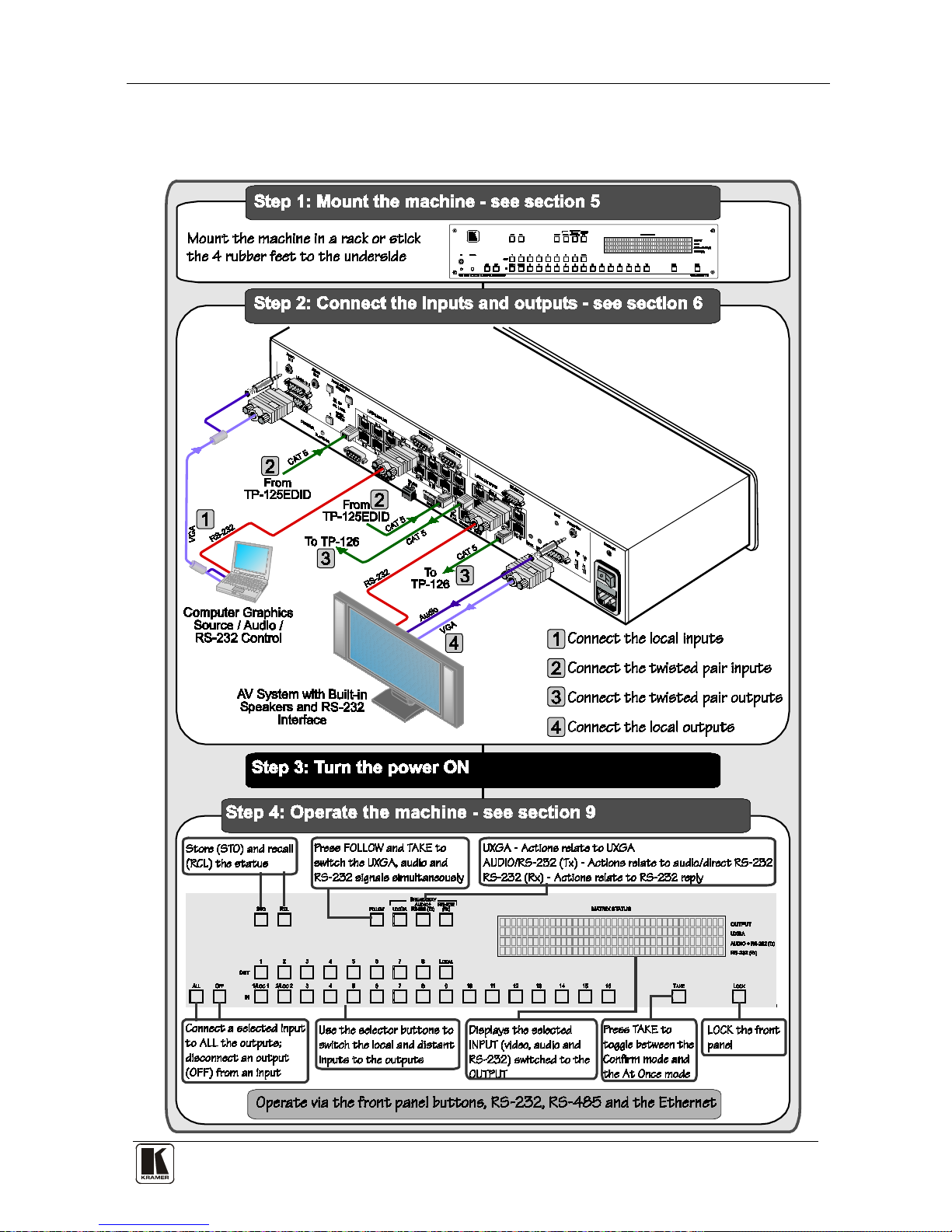
2.4 Quick Start
This quick start chart summarizes the basic setup and operation steps.
Page 8

KRAMER: SIMPLE CREATIVE TECHNOLOGY
Overview
4
3 Overview
The VS-169TP is a high-performance matrix switcher for video signals up to
WUXGA/1080p, analog stereo / S/PDIF audio and bidirectional RS-232
signals, over twisted pair CAT 5 cable. The unit can route any input to any or
all outputs simultaneously.
More specifically, the VS-169TP features:
• Compatibility with most Kramer twisted pair transmitters/receivers
• 16 inputs for remote connection to CAT 5 transmitters and eight outputs
for remote connection to CAT 5 receivers
• Two switchable local inputs (built-in transmitters) and one local output (a
built-in receiver) allowing direct connection of the signals (UXGA, audio
and RS-232) for the units located near to the switcher
• Follow or breakaway switching for all signals (UXGA, audio, RS-232)
• 48kHz/24-bit analog/digital conversion for broadcast quality stereo audio
• Baud rate of up to 19,200 for full-duplex RS-232 together with audio; one
source to multiple destination for straight RS-232 signal and priority
system or user-defined destination for reply signal
• Four-line LCD display for separate route indication of video, audio, or
RS-232
• Control via front panel pushbuttons, RS-232, RS-485, IP and IR remote
control
• 15 user-programmable presets for quick-change configurations
• Kramer 2000 communication protocol
• 100-240V AC worldwide power supply
• Standard 19” rack mount size – 2U
Page 9

Your VS-169TP 16x9 CAT 5 Matrix Switcher
5
3.1 Shielded Twisted Pair (STP) / Unshielded Twisted Pair (UTP)
We recommend that you use shielded twisted pair (STP) cable. There are
different levels of STP cable available, and we advise you to use the best
quality STP cable that you can afford. Our non-skew-free cable, Kramer
BC-STP is intended for digital signals and for analog signals where skewing
is not an issue. For cases where there is skewing, our UTP skew-free cable,
Kramer BC-XTP, may be used. Bear in mind, though, that we advise using
STP cables where possible, since the compliance to electromagnetic
interference was tested using those cables.
Although unshielded twisted pair (UTP) cable might be preferred for long
range applications, the UTP cable should be installed far away from electric
cables, motors and so on, which are prone to create electrical interference.
However, since the use of UTP cable might cause inconformity to electromagnetic
standards, Kramer does not commit to meeting the standard with UTP cable.
4 Your VS-169TP 16x9 CAT 5 Matrix Switcher
Figure 1, Table 1, Figure 2 and Table 2 define the VS-169TP.
Page 10
KRAMER: SIMPLE CREATIVE TECHNOLOGY
Your VS-169TP 16x9 CAT 5 Matrix Switcher
6
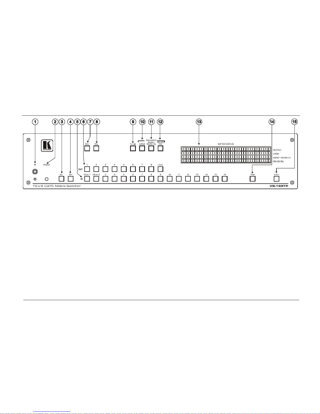
Figure 1: VS-169TP 16x9 CAT 5 Matrix Switcher Front Panel
Page 11

Your VS-169TP 16x9 CAT 5 Matrix Switcher
7
Table 1: VS-169TP 16x9 CAT 5 Matrix Switcher Front Panel Functions
#
Feature
Function
1 IR Receiver/IR LED The red LED is illuminated when receiving signals from the
infrared remote control transmitter
2 POWER LED Illuminates green when receiving power
3 ALL Button Pressing ALL followed by an IN button, connects that input to
all outputs
1
4
OFF Button Press an OUT selector button and then an OFF button to
disconnect that output from the inputs
Press the ALL button and then the OFF button to disconnect
all the outputs
5 IN Buttons (1 to 16) Select the input (including the two local built-in
transmitters) to switch to the output
6 OUT Buttons (1 to 8, LOCAL) Select the output to which the input is switched, including
the local built-in receiver
7 STO Button
Pressing STO followed by an IN button (from 1 to 15)
stores the current setting
2
8
in the non-volatile memory
RCL Button Pressing RCL followed by an IN button (from 1 to 15)
recalls a setup from the non-volatile memory
9 FOLLOW Button Pressing FOLLOW followed by the TAKE button enters the
Follow mode in which the UXGA, audio and RS-232
signals switch simultaneously
10
BREAKAWAY
UXGA Button When pressed twice
3
11
the button illuminates and the actions
that follow will relate to UXGA
AUDIO+RS-232 (Tx)
Button
When pressed twice3 the button illuminates and the actions
that follow will relate to audio/direct
4
12
RS-232
RS-232 (Rx) Button When pressed twice3 the button illuminates and the actions
that follow will relate to RS-232 reply
4
13 MATRIX STATUS 40x4 LCD Display Displays the selected INPUT (video, audio and RS-232)
switched to the OUTPUT
14 TAKE Button Pressing TAKE toggles the mode between the Confirm
mode
5
15
and the At Once mode (user confirmation per action
is unnecessary). When in Confirm mode, pressing the
TAKE button will implement a pending configuration
LOCK Button Toggles activation/inactivation of the front panel buttons.
When the front panel is locked you can still control via the
interfaces
1 For example, press ALL and then IN button # 3 to connect input # 3 to all the outputs
2 For example, press STO and then the IN button # 3 to store in Setup # 3
3 After pressing once, the button blinks
4 Direct RS-232 refers to the signal transmitted from the transmitter to the receiver; RS-232 reply refers to the signal returned
from the receiver to the transmitter
5 When in the Confirm mode, the TAKE button illuminates
Page 12
KRAMER: SIMPLE CREATIVE TECHNOLOGY
Your VS-169TP 16x9 CAT 5 Matrix Switcher
8
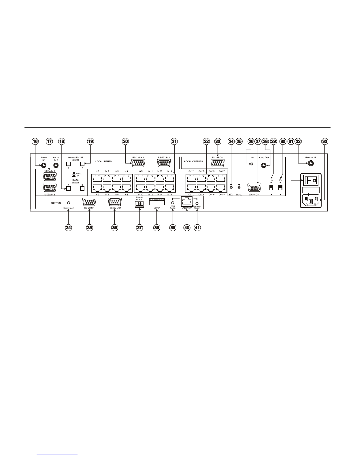
Figure 2: VS-169TP 16x9 CAT 5 Matrix Switcher Rear Panel
Page 13

Your VS-169TP 16x9 CAT 5 Matrix Switcher
9 9
Table 2: VS-169TP 16x9 CAT 5 Matrix Switcher Rear Panel Functions
#
Feature
Function
16
LOCAL INPUTS
AUDIO IN 3.5mm Mini Jack Connect to the local audio source (for local inputs 1 and 2)
17 UXGA IN 15-pin Connector Connect to the UXGA source (for local inputs 1 and 2)
18 UXGA SELECT Pushbuttons Select the remote or LOCAL (built-in) receiver for input 1 and
input 2 for UXGA
19 AUDIO/RS-232 SELECT
Pushbuttons
Select the remote or LOCAL (built-in) receiver for input 1 and
input 2 for AUDIO and RS-232
20 RS-232 IN 9-pin D-sub
Connectors
Connect to the RS-232 source for local inputs 1 and 2
21 IN (1 to 16) RJ-45 Connectors Connect to the LINE OUT RJ-45 connectors of the remote
transmitters via CAT 5
22 OUT (1 to 8) RJ-45 Connectors Connect to the LINE IN RJ-45 connector of the remote receivers
via CAT 5
23
LOCAL OUTPUTS
RS-232 OUT 9-pin D-sub
Connectors
Connect to the RS-232 local acceptor
24 EQ. Trimmer Adjusts the cable compensation equalization level for the local
built-in receiver
25 LEVEL Trimmer Adjusts the output signal level for the local built-in receiver
26 LINK LED Illuminates when the local receiver receives the correct input signal
27 UXGA OUT 15-pin Connector Connects to the UXGA local acceptor
28 AUDIO OUT 3.5mm Mini Jack Connects to the analog audio local acceptor
29 HS Switch Slide down
1
30
to set the H SYNC to negative polarity (-);
slide up to set the H SYNC to positive polarity (+)
VS Switch Slide down1 to set the V SYNC to negative polarity (+);
slide up to set the V SYNC to positive polarity (-)
31 POWER Switch Switch for turning the unit ON and OFF
32 REMOTE IR 3.5mm Mini Jack
2
Connect to an external IR receiver unit for controlling the machine via
an IR remote controller (instead of using the front panel IR receiver)
3
33 POWER IN with fuse
AC connector enabling power supply to the VS-169TP
34
CONTROL
FLASH MAIN Push in
4
10.1
to upgrade the switcher microcontroller to the latest
Kramer firmware (see
Section ), or release (the factory
default) for normal operation
35 RS-232 IN 9-pin D-sub Port Connect to the PC or the remote controller
36 RS-232 OUT 9-pin D-sub Port Connects to the RS-232 IN 9-pin D-sub F port of the next unit in
the daisy-chain connection
37 RS-485 Terminal Block Port Pins B (-) and A (+) are for RS-485; connect pin G to the cable
shield (if required)
38 SETUP DIP-switches For setup of the unit (see Section 6.2)
39 ETH FLASH Pushbutton Push in4 to upgrade the ETH FLASH firmware version (see Section
10.2), or release (the factory default) for normal operation
40 ETHERNET Connector Connects to the PC or other Serial Controller through computer
networking LAN
1 By default, both switches are set down (for a negative V SYNC and H SYNC polarity)
2 Covered by a cap. The 3.5mm connector at the end of the internal IR connection cable fits through this opening
3 Optional. Can be used instead of the front panel (built-in) IR receiver to remotely control the VS-169TP (only if the internal
IR connection cable has been installed)
4 Using a small screwdriver, if required
Page 14

KRAMER: SIMPLE CREATIVE TECHNOLOGY
Your VS-169TP 16x9 CAT 5 Matrix Switcher
10
#
Feature
Function
41 FACTORY RESET Pushbutton Press to reset to factory default definitions
1
:
IP Address: 192.168.1.39
Mask: 255.255.255.0
Gateway: 192.168.1.1
4.1 Using the IR Transmitter
You can use the RC-IR2 IR transmitter to control the VS-169TP via the
built-in IR receiver on the front panel or, instead, via an optional external IR
receiver
2
. The external IR receiver can be located 15 meters away from the
machine. This distance can be extended to up to 60 meters when used with
three extension cables
3
Before using the external IR receiver, be sure to arrange for your Kramer
dealer to insert the internal IR connection cable
15F
4
with the 3.5mm connector
that fits into the REMOTE IR opening on the rear panel. Connect the external
IR receiver to the REMOTE IR 3.5mm connector.
1 Turn the machine OFF using the power switch and then turn it ON while pressing the ETH Factory Reset button. The unit
will power up and load its memory with the factory default definitions
2 Model: C-A35M/IRR-50
3 Model: C-A35M/A35F-50
4 P/N: 505-70434010-S
Page 15

Installing the VS-169TP in a Rack
11 11
5 Installing the VS-169TP in a Rack
.
This section describes how to install the VS-169TP in a rack.
Page 16

KRAMER: SIMPLE CREATIVE TECHNOLOGY
Connecting the VS-169TP 16x9 CAT 5 Matrix Switcher
12
5.1 Wiring the CAT 5 LINE IN / LINE OUT RJ-45 Connectors
Table and 3 Figure define the UTP/FTP3
1
Table 3: CAT 5 PINOUT
CAT 5 PINOUT, using a straight
pin to pin cable with RJ-45 connectors:
Figure 3: CAT 5 PINOUT
36
7
81 2
5
4
1
4
5 7
8632
EIA /TIA 568A EIA /TIA 568B
PIN
Wire Color
PIN
Wire Color
1 Green / White 1 Orange / White
2 Green 2 Orange
3 Orange / White 3 Green / White
4 Blue 4 Blue
5 Blue / White 5 Blue / White
6 Orange 6 Green
7 Brown / White 7 Brown / White
8 Brown 8 Brown
Pair 1 4 and 5 Pair 1 4 and 5
Pair 2 3 and 6 Pair 2 1 and 2
Pair 3 1 and 2 Pair 3 3 and 6
Pair 4 7 and 8 Pair 4 7 and 8
6 Connecting the VS-169TP 16x9 CAT 5 Matrix Switcher
To connect the VS-169TP as shown in the example in Figure 4, do the
following
2
1. For signal sources that are located near the VS-169TP (the LOCAL
INPUTS):
:
A UXGA source (for example, the graphics output on a laptop) to the
UXGA IN 1 15-pin HD (F) connector
3
An audio source to the AUDIO IN 1 3.5mm mini jack
4
, for example,
using a Kramer C-GMA/GMA cable (VGA 15-pin HD (M) +Audio
jack to VGA 15-pin HD (M) +Audio jack)
5
An RS-232 cable with a 9-pin D-sub connector to the PC or controller
at one end, and a 9-pin D-sub connector at the other end to the
RS-232 IN 1 and/or the RS-232 IN 2.
1 FTP means Foiled twisted pair
2 Switch OFF the power on each device before connecting it to your VS-169TP. After connecting your VS-169TP, switch on
its power and then switch on the power on each device
3 You can connect UXGA IN 1 and/or UXGA IN 2
4 You can connect AUDIO IN 1 and/or AUDIO IN 2
5 Not supplied. The full list of Kramer cables is on our Web site at http://www.kramerelectronics.com. Alternatively, you can
connect an UXGA source to the UXGA IN 15-pin HD (F) connector, and a separate audio source to the AUDIO IN 3.5mm
mini jack
Page 17

Connecting the VS-169TP 16x9 CAT 5 Matrix Switcher
13 13
2. For signal destinations that are located near the VS-169TP (the LOCAL
OUTPUT):
The UXGA OUT 15-pin HD (F) connector to the UXGA monitor
The AUDIO OUT 3.5mm mini jack to the self-powered speaker
system
An RS-232 cable with a 9-pin D-sub connector to the RS-232 OUT at
one end, and a 9-pin D-sub connector at the other end to the RS-232
IN of the controlled unit
If required, adjust the cable compensation equalization level and/or
video output signal level with a screwdriver
If necessary, set the H SYNC and V SYNC switches
1
3. For signal sources that are located at a distance from the VS-169TP,
connect the remote transmitters/receivers as follows:
Connect up to 16 transmitters
2
(for example, the Kramer
TP-125EDID XGA / Audio / Data Line Transmitter
3
Connect up to eight receivers
)
2
(for example, the Kramer TP-126
UXGA / Audio / Data Line Transmitter
3
)
4. Connect the 12V DC power supply to the power socket and connect the
adapter to the mains electricity on both the transmitters and the receivers.
5. If required, connect a PC or controller to the RS-232 ports (see
Section
7.1) or the RS-485 port (see 7.2Section ) or the ETHERNET port (see
7.3Section
6. If required, set the DIP-switches (see
).
Section 6.2
7. Connect the power cord
).
4
1 By default, both switches are set down (for negative V SYNC and H SYNC polarity)
.
2 You do not have to connect all the inputs and outputs
3 Download up-to-date Kramer user manuals from our Web site at http://www.kramerelectronics.com
4 We recommend that you use only the power cord that is supplied with this machine
Page 18

KRAMER: SIMPLE CREATIVE TECHNOLOGY
Connecting the VS-169TP 16x9 CAT 5 Matrix Switcher
14
Figure 4: Connecting the VS-169TP 16x9 CAT 5 Matrix Switcher
Page 19

Connecting the VS-169TP 16x9 CAT 5 Matrix Switcher
15 15
6.1 Connecting the RS-232 Ports
The VS-169TP includes the following RS-232 ports:
• Two local RS-232 IN ports and one local RS-232 OUT port (see
Section
6.1.1
• RS-232 IN and RS-232 OUT control ports (see
) to transmit RS-232 signals along with the video and audio signals
from the source to the destination units
Section 6.1.2
6.1.1 Connect the Local RS-232 Ports
) to control
the matrix itself (same functions as the RS-485 and IP interfaces)
To connect a PC or controller to the local ports, connect the 9-pin D-sub ports
of the PC or controller to the LOCAL IN RS-232 IN 1 and/or RS-232 IN 2
ports, and to the LOCAL RS-232 OUT port of the VS-169TP unit (via
RS-232 cables), as required.
6.1.2 Connect the Control RS-232 Ports
To connect a PC to the VS-169TP unit:
1. Connect the RS-232 9-pin D-sub port on your PC to the CONTROL
RS-232 IN 9-pin D-sub rear panel port of the VS-169TP with a 9-wire
cable
1
2. Make sure that DIP 7 is set to ON
.
2
6.2 Setting the DIP-switches
.
Figure and 5 Table define the VS-169TP DIP-switches. By default the
VS-169TP (when used as a single unit) is set to Machine #1 (see
4
Table ).
When connecting more than one VS-169TP unit, allocate a unique Machine #
to the VS-169TP. The line termination DIP-switch is for use only with the
RS-485 port.
5
Machine Number
RS-232 Termination
Figure 5: DIP-switch Settings
Table 4: DIP-switch Settings
DIPS
Description
1, 2, 3, 4 Set the MACHINE # (see Section 6.2.1)
5, 6 Not used
7 Set ON to avoid having to connect a null-modem
adapter or using a null-modem connection
8 Set ON for RS-485 termination for the first and the
last machine (RS-485 line terminates with 110Ω);
for others set OFF (RS-485 line is open)
1 The cable should consist of at least three straight-through wires: PINs 2, 3 and 5
2 See Section
6.2
Page 20

KRAMER: SIMPLE CREATIVE TECHNOLOGY
Connecting the VS-169TP 16x9 CAT 5 Matrix Switcher
16
6.2.1 Setting the Machine #
To control a unit remotely via RS-232, RS-485, IR or the Ethernet, each unit
has to be identified via its unique Machine #. Set the Machine #
1
on a
VS-169TP unit according to
Table 5.
Table 5: Machine # DIP-switch Settings
Mach. #
DIP 1
DIP 2
DIP 3
DIP 4
Mach. #
DIP 1
DIP 2
DIP 3
DIP 4
1 ON OFF OFF OFF 9 ON OFF OFF ON
2 OFF ON OFF OFF 10 OFF ON OFF ON
3 ON ON OFF OFF 11 ON ON OFF ON
4 OFF OFF ON OFF 12 OFF OFF ON ON
5 ON OFF ON OFF 13 ON OFF ON ON
6 OFF ON ON OFF 14 OFF ON ON ON
7 ON ON ON OFF 15 ON ON ON ON
8 OFF OFF OFF ON
1 When using a single unit, set the unit to MACHINE # 1
Page 21

Control the VS-169TP 16x9 CAT 5 Matrix Switcher
17 17
7 Control the VS-169TP 16x9 CAT 5 Matrix Switcher
You can use a PC to control the VS-169TP unit via:
• An RS-232 interface (see
Section 7.1
• An RS-485 interface (see ) Section 7.2
• The Ethernet port (see ) Section 7.3
When connecting several units, always use only one type of interface, the
RS-232 or the RS-485. Do not mix them
)
7.1 Controlling via the RS-232 Interface
To control the VS-169TP via the RS-232 interface:
1. Connect the RS-232 IN 9-pin D-sub port
1
of the VS-169TP unit to a PC
(see
Section 6.1
2. Set the machine # to any number from 1 to 15 (see
).
Table 5).
Figure 6: Controlling the VS-169TP via the RS-232 Interface
If several Kramer units are connected to one PC, use the daisy chain
connection (PC to RS-232 IN, RS-232 OUT to RS-232 IN on the next
machine, and so on).
1 Alternatively, the ETHERNET port could be used for PC control (instead of RS-232)
Page 22

KRAMER: SIMPLE CREATIVE TECHNOLOGY
Control the VS-169TP 16x9 CAT 5 Matrix Switcher
18
7.2 Controlling via the RS-485 Interface
To control the VS-169TP unit via the RS-485 interface (see
Figure 7):
1. Connect the 9-pin D-sub COM port of the PC to the RS-232 IN 9-pin D-
sub F port on the VP-43xl.
2. Connect the RS-485 port on the VP-43xl to the RS-485 port on the
VS-169TP.
3. Set the Machine # to any number from 1 to 15 (see
Table 5).
Figure 7: Controlling the VS-169TP via the RS-485 Interface
Page 23

Control the VS-169TP 16x9 CAT 5 Matrix Switcher
19 19
7.3 Controlling via the ETHERNET
You can connect the VS-169TP via the Ethernet, using a crossover cable
(see
Section 7.3.1) for direct connection to the PC or a straight through cable
(see
7.3.2Section ) for connection via a network hub or network router
1
7.3.1 Connecting the ETHERNET Port directly to a PC (Crossover Cable)
.
You can connect the Ethernet port of the VS-169TP to the Ethernet port on
your PC, via a crossover cable with RJ-45 connectors.
This type of connection is recommended for identification of the factory default
IP Address of the VS-169TP during the initial configuration
After connecting the Ethernet port, configure your PC as follows:
1. Right-click the My Network Places icon on your desktop.
2. Select Properties.
3. Right-click Local Area Connection Properties.
4. Select Properties.
The Local Area Connection Properties window appears.
5. Select the Internet Protocol (TCP/IP) and click the Properties Button (see
Figure 8).
Figure 8: Local Area Connection Properties Window
1 After connecting the Ethernet port, you have to install and configure your Ethernet Port. For detailed instructions, see the
“Ethernet Configuration (FC-11) guide.pdf” file in the technical support section on our Web site:
http://www.kramerelectronics.com
Page 24

KRAMER: SIMPLE CREATIVE TECHNOLOGY
Control the VS-169TP 16x9 CAT 5 Matrix Switcher
20
6. Select Use the following IP Address, and fill in the details as shown in
Figure 9.
7. Click OK.
Figure 9: Internet Protocol (TCP/IP) Properties Window
7.3.2 Connecting the ETHERNET Port via a Network Hub (Straight-Through
Cable)
You can connect the Ethernet port of the VS-169TP to the Ethernet port on a
network hub or network router, via a straight-through cable with RJ-45
connectors.
7.3.3 Control Configuration via the Ethernet Port
To control several units via the Ethernet, connect the unit (Machine # 1) via
the Ethernet port to the LAN port of your PC. Use your PC initially to
configure the settings.
Page 25

Understanding the VS-169TP 16x9 CAT 5 Matrix Switcher
21 21
8 Understanding the VS-169TP 16x9 CAT 5 Matrix Switcher
The VS-169TP is a 16x9 matrix switcher for CAT 5/6 twisted pair
transmitters and receivers, capable of sending (over UTP/FTP twisted-pair
cables) UXGA, analog stereo/ S/PDIF audio, and bidirectional RS-232
command/reply signals.
Depending on the transmitter and receiver models connected to the
VS-169TP
1
• UXGA
, it is possible to send the following signals:
• UXGA with analog stereo/ S/PDIF audio, or
• UXGA with analog stereo and bidirectional RS-232 commands at the
same time
Any of the inputs can be switched to any or all outputs.
IN 1 and IN 2 can be used for accepting signals either from the local (built-in)
or remote transmitters (see
Section 9.1
8.1 Transmitting the RS-232 Signal
). Inputs 3 to 16 accept only signals
from the connected remote transmitters. Outputs 1 to 8 transmit the incoming
signal to the remote receivers, and output 9 locally decodes all the signals and
outputs these as regular UXGA, analog audio and RS-232 signals.
The video and audio signals are always transmitted in one direction, when
using the VS-169TP, from the source (via the input) to the acceptor (via the
output). However, the RS-232 signal behaves entirely differently:
• It is not a continuous signal, but consists of one or a series of short
messages (commands), which pass the matrix from the input to the output
• The destination unit sends a reply for each command that is received,
consisting of other short messages (replies), which pass the VS-169TP
from the output to the input, back to the source of the command
Consequently, the VS-169TP needs bidirectional RS-232 signals.
Kramer twisted pair technology embeds the RS-232 command in the audio
stream so that it is transmitted on the same pair as the audio signal. In this
way the audio signal and the RS-232 command always pass the switcher
together even in the breakaway mode. The RS-232 reply can be switched
separately (see
Section 9.7.2 ).
1 For example, TP-125EDID and TP-126, or TP-121 and TP-122
Page 26

KRAMER: SIMPLE CREATIVE TECHNOLOGY
Understanding the VS-169TP 16x9 CAT 5 Matrix Switcher
22
In the example illustrated in Figure 10, when the transmitter (video, audio and
RS-232 signals) connected to IN 10 is switched to OUT 5, all three signals
are passed to the receiver connected to OUT 5, and the RS-232 reply
command returns from the receiver (OUT 5) back to the transmitter (IN 10).
IN 10
OUT 5
UXGA
AUDIO + RS-232 (Tx)
RS-232 (Rx)
Figure 10: Switching an Input to an Output
In the example illustrated in Figure 11, the transmitter (video, audio and
RS-232 signals) connected to IN 10 is switched to OUT 3, OUT 5 and OUT 8 –
each of which is connected to a receiver. The signals are passed to all the
outputs and the RS-232 signal generates a reply command on each receiver.
The reply signal on each receiver contains not only different information, but
can be sent at different times and in different formats. When this information is
passed back to IN 10, it might be rejected by the control unit since it includes a
mix of reply signals, and control of the destination units becomes impossible.
To avoid a mixed RS-232 reply command, the VS-169TP passes only one
reply from the output back to the input. In the FOLLOW mode, the
VS-169TP passes the RS-232 reply from the output which has the lowest
numerical value (in this example, OUT 3). Other RS-232 replies are blocked.
IN 10
OUT 3
Blocked
Blocked
OUT 5
OUT 8
UXGA
AUDIO + RS-232 (Tx)
RS-232 (Rx)
UXGA
AUDIO + RS-232 (Tx)
RS-232 (Rx)
UXGA
AUDIO + RS-232 (Tx)
RS-232 (Rx)
Figure 11: Switching an Input to Several Outputs
Page 27

Operating the VS-169TP 16x9 CAT 5 Matrix Switcher
23 23
Figure 12 shows the MATRIX STATUS display in the Follow Mode:
0
0
0 0
0
LL000
1
11
0
1
1 3 4 7
8
-652
0
00
3
0
00
Figure 12: MATRIX STATUS Display in the Follow Mode
In the breakaway mode, you can select the output port from which the reply
will be returned, by pressing the RS-232 (Rx) front panel button in the
BREAKAWAY area, and then selecting the desired output (see
Section 9.7
9 Operating the VS-169TP 16x9 CAT 5 Matrix Switcher
).
This section describes how to:
• Toggle inputs #1 and #2 between local and remote inputs (see Section
9.1
• Read the 7-segment displays (see ) Section 9.3.1
• Use the IN and OUT buttons (see ) Section 9.3
• Confirm settings (see ) Section 9.4
• Store and recall input/output configurations (see ) Section 9.5
• Lock the front panel (see ) Section 9.6
• Choose the audio-follow-video or the breakaway feature (see ) Section 9.7
9.1 Switching Inputs #1 and #2 between local and remote
)
You can select the function of the IN 1 and IN2 front panel buttons to be either
local or remote (TP), via the four rear panel SELECT pushbuttons (items 18 and
19 in
Figure 2).
The UXGA SELECT buttons define the VIDEO signal and the AUDIO/RS-232
SELECT buttons define the AUDIO and RS-232 signals. All four buttons switch
independently.
This setting can only be changed via these rear panel buttons and cannot be
changed from the front panel or any other interface command.
Page 28

KRAMER: SIMPLE CREATIVE TECHNOLOGY
Operating the VS-169TP 16x9 CAT 5 Matrix Switcher
24
9.2 The STATUS 7-Segment Display
During normal operation, the STATUS display shows which inputs (UXGA,
AUDIO and/or RS-232) are switched to which outputs, as illustrated in
Figure 13
:
0
0
0 0
0
0
0
LL000
0
1
0 1 0000
0
0
0
0
0
0 1 0 1 0000
1 3 4 7
8
8
8
-652
1
6
8 3 5881
1
3
4
7
8
1
6
8 3 5881
Figure 13: 7-segment Display During Normal Operation
Figure 14 shows an example of the display immediately after switching on
the power:
KRAMER
UXGA
16in 8+1out Twisted Pairs MATRIX
STEREO AUDIO FULL DUPLEX RS-232-
-
-
ELECTRONICS, Ltd
VS-169TP/Rev
1 . 0
Figure 14: 7-segment Display Following Power ON
9.3 Switching an Input to an Output
To switch an input to an output:
1. Press the required OUT button from 1 to 8 or the L-L (local, on the
display).
The input under the selected output on the IN 7-segment display blinks.
2. Press an IN button to select the input to switch to the output.
The selected input number appears on the 7-segment display.
Incomplete operations on the VS-169TP timeout after 25 seconds
9.3.1 Switching one Input to all Outputs
To switch one input to all the outputs (in the AT ONCE mode):
1. Press the ALL button.
The MATRIX STATUS display shows the three sets of digits
1
1 Each representing the present input number for that respective output
in the
follow mode blinking simultaneously. In the breakaway mode, only the
Page 29

Operating the VS-169TP 16x9 CAT 5 Matrix Switcher
25 25
line of the selected signal blinks.
2. Press the appropriate IN button.
This input switches to all the outputs, and the MATRIX STATUS display
shows the selected input number.
To switch one input to all the outputs in the CONFIRM mode (the TAKE
button illuminates), do the following:
1. Press the ALL button.
The MATRIX STATUS display shows the three sets of blinking digits
(each representing the present input number for that respective output)
blinking simultaneously.
2. Press the appropriate IN button.
The current input settings blink alternately with the selected input number
digits, and the TAKE button blinks.
3. Press the TAKE button to confirm the action.
The selected input switches to all the outputs and the TAKE button
illuminates. The MATRIX STATUS display shows the identical digits
(representing the selected input number) for all outputs.
9.3.2 Clearing an Output
To clear an output (in the AT ONCE mode):
1. Press the appropriate OUT button.
The MATRIX STATUS display shows the two blinking digits,
representing the present input number for that specific output.
2. Press the OFF button.
The input is cleared and the MATRIX STATUS display does not show
any input number in its place.
9.3.3 Clearing all the Outputs
To clear all outputs (in the AT ONCE mode):
1. Press the ALL button.
The MATRIX STATUS display shows the three sets of digits
1
2. Press the OFF button.
The MATRIX STATUS display shows: RESET ALL OUTPUTS?
CONFIRM
and the TAKE button blinks.
blinking
simultaneously. In the breakaway mode, only the line of the selected
signal blinks
1 Each representing the present input number for that respective output
Page 30

KRAMER: SIMPLE CREATIVE TECHNOLOGY
Operating the VS-169TP 16x9 CAT 5 Matrix Switcher
26
3. Press the TAKE button to confirm the action.
All the outputs are cleared.
9.4 Confirming Settings
You can choose to work in the At Once or the Confirm mode.
In the At Once mode (TAKE button does not illuminate):
• Pressing an OUT-IN combination implements the switch immediately
• You save time as execution is immediate and actions require no user
confirmation
• No protection is offered to allow the correction of an erroneous action
before it is implemented
In the Confirm mode (TAKE button illuminates):
• You can key-in and then confirm it by pressing the TAKE button, to
simultaneously activate the multiple switches
• Every action requires user confirmation, protecting against erroneous
switching
• Execution is delayed
1
9.4.1 Toggling between the At Once and Confirm Modes
until the user confirms the action
To toggle between the At Once and Confirm modes, do the following:
1. Press the TAKE button to toggle from the At Once mode (in which the
TAKE button does not illuminate) to the Confirm mode (in which the
TAKE button illuminates).
Actions now require user confirmation and the TAKE button illuminates.
2. Press the illuminated TAKE button to toggle from the Confirm mode
back to the At Once mode.
Actions no longer require user confirmation and the TAKE button no
longer illuminates.
These actions cannot take place when the TAKE button blinks
9.4.2 Confirming a Switching Action
To confirm a switching action (in the Confirm mode), do the following:
1. Press an OUT-IN combination.
The corresponding 7-segment display blinks and the MATRIX
SELECTOR display alternates between “CURRENT” and “UPDATED”.
The TAKE button also blinks.
1 Failure to press the TAKE button within one minute (the Timeout) will abort the action
Page 31

Operating the VS-169TP 16x9 CAT 5 Matrix Switcher
27 27
2. Press the blinking TAKE button to confirm the action.
The corresponding 7-segment display no longer blinks. The TAKE button
illuminates.
9.5 Storing/Recalling Input/Output Configurations
You can store and recall up to 15 input configurations
1
using the 16 IN buttons.
9.5.1 Storing an Input/Output Configuration
To store the current status in memory, do the following:
1. Press the STO button.
The STO button blinks and the MATRIX SELECTOR displays:
Store setup #_
2. Press one of the 16 IN front panel buttons (this will be the setup # in
which the current status is stored).
If the input already has a stored setting, the MATRIX SELECTOR
displays: #15=>NOT EMPTY. OVERWRITE? (for example, for
storing a setting in IN 15).
If there is no setting stored in the selected input, the MATRIX
SELECTOR displays: STORED! The memory stores the data at that
reference.
In the Confirm mode, press the blinking TAKE button to confirm the action.
9.5.2 Recalling an Input/Output Configuration
To recall an input/output configuration, do the following:
1. Press the RCL button.
The RCL button blinks.
Recall setup #_
2. Press the appropriate IN button (the button # corresponding to the setup #).
The current and new setting inputs blink alternately.
If in the Confirm mode, MATRIX SELECTOR display shows: “Current”
and Updated” blinking alternately, together with the RCL button and the
TAKE button, and will only be implemented after pressing the TAKE
button.
The memory recalls the stored data from that reference.
Tip: If you cannot remember which of the 15 input configurations is the one
that you want, set the VS-169TP to the Confirm mode and manually scan
2
1 You can store and recall audio and video configurations and audio gain data
all
the input/output configurations until you locate it.
2 By pressing the RCL button followed by the INPUT/OUTPUT buttons
Page 32

KRAMER: SIMPLE CREATIVE TECHNOLOGY
Operating the VS-169TP 16x9 CAT 5 Matrix Switcher
28
9.6 Locking the Front Panel
To prevent changing the settings accidentally or tampering with the unit via
the front panel buttons, lock
1
To lock the VS-169TP:
your VS-169TP. Unlocking releases the
protection mechanism.
• Press the LOCK button until the LOCK button is illuminated.
The front panel is locked. Pressing a button will have no effect other than
causing the LOCK button to blink
2
To unlock the VS-169TP:
• Press the illuminated LOCK button until the LOCK button is no longer
illuminated and the front panel unlocks
9.7 Choosing the Follow or Breakaway Operation Mode
The VS-169TP can operate either in the Follow mode or the Breakaway mode:
• Press the FOLLOW front panel button to set the VS-169TP to the
FOLLOW mode, where all operations relate to the UXGA, AUDIO and
RS-232 channels (the FOLLOW and TAKE buttons blink).
• Press one of the BREAKAWAY buttons (UXGA, AUDIO + RS-232 (Tx)
or RS-232 (Rx)). The selected button blinks
Press it a second time to operate in the breakaway mode
9.7.1 Follow Mode Operation
In the FOLLOW operation mode all the operations relate to the video, audio
and RS-232 signals. The matrix automatically selects the RS-232 reply sent
by the lowest number output.
By default, the VS-169TP is set to the FOLLOW mode.
To return to the VS-169TP to the Follow operation mode
3
1. Press the FOLLOW front panel button.
The FOLLOW button and the TAKE button blink
:
4
2. Press the TAKE button.
.
1 Even when the front panel is locked you can still operate via RS-232 or RS-485, as well as via the Kramer RC-IR2 infrared
Remote Control Transmitter
2 Warning that you need to unlock to regain control via the front panel
3 After operating in the Breakaway mode
4 Since the audio and video signals may be set differently
Page 33

Operating the VS-169TP 16x9 CAT 5 Matrix Switcher
29 29
9.7.2 Breakaway Mode Operation
To set the VS-169TP to the Breakaway mode:
1. Press one of the BREAKAWAY buttons (UXGA, AUDIO + RS-232 (Tx)
or RS-232 (Rx)).
The selected button blinks.
2. Press the desired channel a second time.
In the Breakaway operation mode you can switch the different channels
independently. For example, when selecting UXGA in the breakaway mode,
you can switch the video inputs independently from the audio and RS-232
channels.
The same applies when selecting AUDIO + RS-232 (Tx), letting you switch
them without switching the UXGA signal.
When pressing the RS-232 (Rx) button, you can manually select the output
from which the RS-232 reply is sent back to the input.
In the example illustrated in
Figure 11
on page 22, the RS-232 is selected
automatically. Selecting the RS-232 (Rx) in the Breakaway mode, lets you
select output 5 (instead of output 3) to reply to the command transmitted from
input 10, as illustrated in
Figure 15.
The reply command from any output can be sent back only to the input which
transmitted the command. If there are several outputs, the breakaway option
lets you select the reply from a certain output, as illustrated in
Figure 15.
Page 34

KRAMER: SIMPLE CREATIVE TECHNOLOGY
Operating the VS-169TP 16x9 CAT 5 Matrix Switcher
30
IN 10
OUT 3
Blocked
Blocked
OUT 5
OUT 8
UXGA
AUDIO + RS-232 (Tx)
RS-232 (Rx)
UXGA
AUDIO + RS-232 (Tx)
RS-232 (Rx)
UXGA
AUDIO + RS-232 (Tx)
RS-232 (Rx)
Figure 15: Operating in the RS-232 (Rx) Breakaway Mode
Figure 16 shows the MATRIX STATUS display in the RS-232 (Rx)
Breakaway Mode:
0
0
0 0
0
LL00
0
0
1
11
1
1 3 4 7
8
-65
5
2
0
00
0
00
Figure 16: MATRIX STATUS Display in the RS-232 (Rx) Breakaway Mode
Page 35

Flash Memory Upgrade
31 31
10 Flash Memory Upgrade
You upgrade both the VS-169TP:
• Switcher Firmware (see
Section 10.1
• Ethernet Firmware (see ) Section 10.2
10.1 Switcher Firmware Upgrade
)
The VS-169TP uses a microcontroller that runs firmware located in FLASH
memory.
The latest version of firmware and installation instructions can be
downloaded from the Kramer Web site at
www.kramerelectronics.com
10.2 Ethernet Firmware Upgrade
.
The VS-169TP firmware is located in FLASH memory, which lets you
upgrade to the latest Kramer firmware version in minutes!
The process involves:
• Downloading the upgrade package from the Internet
• Connecting the PC to the RS-232 port
• Upgrading the firmware
10.2.1 Downloading from the Internet
You can download the up-to-date file
1
1. Go to our Web site at
from the Internet. To do so:
http://www.Kramerelectronics.com and download
the file: “SetKFRETH11-xx.zip”
from the technical support section.
2. Extract the file “SetKFRETH11-xx.zip”
package, which includes the
KFR-Programmer application setup and the .s19 firmware file, to a folder
(for example, C:\Program Files\KFR Upgrade).
3. Install the KFR-Programmer Application.
10.2.2 Connecting the PC to the RS-232 Port
Before installing the latest Kramer Ethernet firmware version on the
VS-169TP, do the following:
1. Connect the RS-232 9-pin D-sub rear panel port according to
Section 6.1
2. Push the rear panel ETHERNET FLASH button to Program using a
small screwdriver.
.
3. Connect the power on your machine.
1 File names are liable to change from time to time
Page 36

KRAMER: SIMPLE CREATIVE TECHNOLOGY
Flash Memory Upgrade
32
10.2.3 Upgrading Firmware
Follow these steps to upgrade the firmware:
1. Double click the KFR-Programmer desktop icon.
The KFR-Programmer window appears (see
Figure 17
).
Figure 17: The KFR-Programmer Window
2. Select the required COM Port
1
3. Press the File button to select the .s19 firmware file included in the
package.
.
4. Press the Send button to download the file. The Send button lights red.
5. Wait until downloading is completed and the red Send button turns off.
6. Disconnect the power on the VS-169TP.
7. Release the ETHERNET FLASH button on the rear panel.
8. Connect the power on your machine.
1 To which the VS-169TP is connected on your PC
Page 37

Technical Specifications
33
11 Technical Specifications
The VS-169TP technical specifications are shown in Table 6:
Table 6: VS-169TP Technical Specifications1
SIGNAL INPUTS: 16 CAT 5 remote transmitters on RJ-45 connectors
2 local RGBHV UXGA on 15-pin HD connectors
2 local stereo analog audio on 3.5mm mini connectors
2 local RS-232 controllers on 9-pin D-sub connectors
SIGNAL OUTPUTS: 8 CAT 5 remote receivers on RJ-45 connectors
1 local RGBHV UXGA on a 15-pin HD connector
1 local stereo analog audio on a 3.5mm mini connector
1 local RS-232 controllers on a 9-pin D-sub connector
CONTROL INPUTS/OUTPUTS: 1 RS-232 Input on a 9-pin D-sub connector
1 RS-232 Output on a 9-pin D-sub connector
1 RS-485 Input/Output on a 3-pin detachable terminal block
1 Ethernet Input/Output on an RJ-45 connector
RESOLUTION (VIDEO): Up to WUXGA; HD compatible
SAMPLE RATE (AUDIO): 24bit, 48kHz
BAUD RATE (RS-232): Up to 19200
CONTROL (LOCAL VIDEO OUT): EQ: 0 to +33dB @50MHz; Level: -7.5dB to +4.4dB; H & V polarity
S/N RATIO (AUDIO): >80dB
THD+N (AUDIO): < 0.03%
OPERATING TEMPERATURE: 0° to +40°C (32° to 104°F)
STORAGE TEMPERATURE: –40° to +70°C (–40° to 158°F)
HUMIDITY: 10% to 90%, RHL non-condensing
POWER SOURCE: 100-240VAC, 50-60Hz; 36VA (500mA maximum)
DIMENSIONS: 19" x 7" x 2U W, D, H
WEIGHT: 3.8kg (8.4lbs) approx
ACCESSORIES: Power cord, rack “ears”, Windows®-based control software, remote control
transmitter
OPTIONS: External remote IR receiver cable
12 Hex Table
Table 7 lists the Hex values (which the protocol in Section 13 describes in
more detail) for the VS-169TP:
1 Specifications are subject to change without notice
Page 38

KRAMER: SIMPLE CREATIVE TECHNOLOGY
Hex Table
34
Table 7: VS-169TP Hex Table
LOCAL
OUT 8
OUT 7
OUT 6
OUT 5
OUT 4
OUT 3
OUT 2
OUT1
01
81
89
81
01
81
88
81
01
81
87
81
01
81
86
81
01
81
85
81
01
81
84
81
01
81
83
81
01
81
82
81
01
81
81
81
IN 1
01
82
89
81
01
82
88
81
01
82
87
81
01
82
86
81
01
82
85
81
01
82
84
81
01
82
83
81
01
82
82
81
01
82
81
81
IN 2
01
83
89
81
01
83
88
81
01
83
87
81
01
83
86
81
01
83
85
81
01
83
84
81
01
83
83
81
01
83
82
81
01
83
81
81
IN 3
01
84
89
81
01
84
88
81
01
84
87
81
01
84
86
81
01
84
85
81
01
84
84
81
01
84
83
81
01
84
82
81
01
84
81
81
IN 4
01
85
89
81
01
85
88
81
01
85
87
81
01
85
86
81
01
85
85
81
01
85
84
81
01
85
83
81
01
85
82
81
01
85
81
81
IN 5
01
86
89
81
01
86
88
81
01
86
87
81
01
86
86
81
01
86
85
81
01
86
84
81
01
86
83
81
01
86
82
81
01
86
81
81
IN 6
01
87
89
81
01
87
88
81
01
87
87
81
01
87
86
81
01
87
85
81
01
87
84
81
01
87
83
81
01
87
82
81
01
87
81
81
IN 7
01
88
89
81
01
88
88
81
01
88
87
81
01
88
86
81
01
88
85
81
01
88
84
81
01
88
83
81
01
88
82
81
01
88
81
81
IN 8
01
89
89
81
01
89
88
81
01
89
87
81
01
89
86
81
01
89
85
81
01
89
84
81
01
89
83
81
01
89
82
81
01
89
81
81
IN 9
01
8A
89
81
01
8A
88
81
01
8A
87
81
01
8A
86
81
01
8A
85
81
01
8A
84
81
01
8A
83
81
01
8A
82
81
01
8A
81
81
IN 10
01
8B
89
81
01
8B
88
81
01
8B
87
81
01
8B
86
81
01
8B
85
81
01
8B
84
81
01
8B
83
81
01
8B
82
81
01
8B
81
81
IN 11
01
8C
89
81
01
8C
88
81
01
8C
87
81
01
8C
86
81
01
8C
85
81
01
8C
84
81
01
8C
83
81
01
8C
82
81
01
8C
81
81
IN 12
01
8D
89
81
01
8D
88
81
01
8D
87
81
01
8D
86
81
01
8D
85
81
01
8D
84
81
01
8D
83
81
01
8D
82
81
01
8D
81
81
IN 13
01
8E
89
81
01
8E
88
81
01
8E
87
81
01
8E
86
81
01
8E
85
81
01
8E
84
81
01
8E
83
81
01
8E
82
81
01
8E
81
81
IN 14
01
8F
89
81
01
8F
88
81
01
8F
87
81
01
8F
86
81
01
8F
85
81
01
8F
84
81
01
8F
83
81
01
8F
82
81
01
8F
81
81
IN 15
01
90
89
81
01
90
88
81
01
90
87
81
01
90
86
81
01
90
85
81
01
90
84
81
01
90
83
81
01
90
82
81
01
90
81
81
IN 16
Page 39

Kramer Protocol 2000
35 35
13 Kramer Protocol 2000
The VS-169TP is compatible with Kramer’s Protocol 2000, version 0.51.
This RS-232/RS-485 communication protocol uses four bytes of information
as defined below. The default data rate is 9600 baud, with no parity, 8 data
bits, and 1 stop bit.
Note: Compatibility with Kramer’s Protocol 2000 does not mean that a
machine uses all of the commands below. Each machine uses a sub-set of
Protocol 2000, according to its needs.
Table 8: Protocol Definitions
MSB LSB
DESTINATION INSTRUCTION
0 D N5
N4
N3
N2
N1
N0
7 6 5 4 3 2 1
0
1st byte
INPUT
1
I6
I5
I4
I3
I2
I1
I0 7 6 5 4 3 2 1 0
2nd byte
OUTPUT
1
O6
O5
O4
O3
O2
O1
O0 7 6 5 4 3 2 1 0
3rd byte
MACHINE NUMBER
1
OVR X M4
M3
M2
M1
M0 7 6 5 4 3 2 1 0
4th byte
1
st
BYTE: Bit 7 – Defined as 0.
D – “DESTINATION”: 0 - for sending information to the switchers (from the PC);
1 - for sending to the PC (from the switcher).
N5…N0 – “INSTRUCTION”
The function to be performed by the switcher(s) is defined by the INSTRUCTION (6 bits). Also, if a function is performed
via the machine’s keyboard, then these bits are set with the INSTRUCTION NO. that was performed. The instruction codes
are defined according to the table below (INSTRUCTION NO. is the value to be set for N5…N0).
2
nd
BYTE: Bit 7 – Defined as 1.
I6…I0 – “INPUT”.
When switching (i.e. instruction codes 1 and 2), the INPUT (7 bits) is set as the input number which is to be switched.
Similarly, if switching is done via the machine’s front-panel, then these bits are set with the INPUT NUMBER which was
switched. For other operations, these bits are defined according to the table.
3
rd
BYTE: Bit 7 – Defined as 1.
O6…O0 – “OUTPUT”.
When switching (i.e. instruction codes 1 and 2), the OUTPUT (7 bits) is set as the output number which is to be switched.
Similarly, if switching is done via the machine’s front-panel, then these bits are set with the OUTPUT NUMBER which was
switched. For other operations, these bits are defined according to the table.
4
th
BYTE: Bit 7 – Defined as 1.
Bit 5 – Don’t care.
OVR – Machine number override.
M4…M0 – MACHINE NUMBER.
Used to address machines in a system via their machine numbers. When several machines are controlled from a single serial
port, they are usually configured together with each machine having an individual machine number. If the OVR bit is set, then
all machine numbers will accept (implement) the command, and the addressed machine will reply.
For a single machine controlled via the serial port, always set M4…M0 = 1, and make sure that the machine itself is
configured as MACHINE NUMBER = 1.
Page 40

KRAMER: SIMPLE CREATIVE TECHNOLOGY
Kramer Protocol 2000
36
Table 9: Instruction Codes for Protocol 2000
Note: All values in the table are decimal, unless otherwise stated.
INSTRUCTION
DEFINITION FOR SPECIFIC INSTRUCTION
NOTE
#
DESCRIPTION
INPUT
OUTPUT
0
RESET VIDEO
0 0 1
1 SWITCH VIDEO Set equal to video input
which is to be switched
(0 = disconnect)
Set equal to video output which is
to be switched
(0 = to all the outputs)
2, 15
2
SWITCH AUDIO
Set equal to audio input
which is to be switched
(0 = disconnect)
Set equal to audio output which
is to be switched
(0 = to all the outputs)
2
3
STORE VIDEO STATUS
Set as SETUP #
0 - to store
1 - to delete
2, 3, 15
4 RECALL VIDEO STATUS Set as SETUP # 0 2, 3, 15
5 REQUEST STATUS OF A
VIDEO OUTPUT
Set as SETUP # Equal to output number whose
status is reqd
4, 3
6
REQUEST STATUS OF AN
AUDIO OUTPUT
Set as SETUP #
Equal to output number whose
status is reqd
4, 3
8 BREAKAW AY SETTING 0
0 - audio-follow-video
1 - audio breakaway
2
1 0 - FOLLOW mode
1 - Normal mode
15
11
REQUEST BREAKAW AY
SETTING
Set as SETUP #, or
set to 126 or 127 to
request if machine has this
function
0 - Request audio breakaway
setting
1 - Request “FOLLOW” setting
3, 4, 6, 15
15
REQUEST WHETHER SETUP
IS DEFINED / VALID INPUT IS
DETECTED
SETUP #
or
Input #
0 - for checking if setup is defined
1 - for checking if input is valid
8
16
ERROR / BUSY
For invalid / valid input (i.e.
OUTPUT byte = 4 or
OUTPUT byte = 5),
this byte is set as the input
#
0 - error
1 - invalid instruction
2 - out of range
3 - machine busy
4 - invalid input
5 - valid input
6 - RX buffer overflow
9, 25
18
RESET AUDIO
0 0 1
19 STORE AUDIO STATUS Set as SETUP # 0 - to store
1 - to delete
2, 3
20
RECALL AUDIO STATUS
Set as SETUP #
0
2, 3
30
LOCK FRONT PANEL
0 - Panel unlocked
1 - Panel locked
0
2
31 REQUEST WHETHER PANEL
IS LOCKED
0 0 16
44 SWITCH CONTROL DATA Set equal to control data
input which is to be
switched
(0 = disconnect)
Set equal to control data output
which is to be switched
(0 = to all the outputs)
2,27
45
REQUEST STATUS OF
CONTROL DATA OUTPUT
Set as SETUP #
Equal to output number whose
status is reqd
3,4,27
58
EXECUTE LOADED DATA
Set as 0, or as SETUP #.
1-Take
2-Cancel
22, 3
59 LOAD VIDEO DATA Set equal to video input
(0 = disconnect)
Set equal to video output
(0 = to all the outputs)
22, 23
(127 = load SETUP #)
or SETUP #
60
LOAD AUDIO DATA
Set equal to audio input
(0 = disconnect)
Set equal to audio output
(0 = to all the outputs)
22, 23
(127 = load SETUP #)
or SETUP #
Page 41

Kramer Protocol 2000
37 37
INSTRUCTION DEFINITION FOR SPECIFIC INSTRUCTION NOTE
#
DESCRIPTION
INPUT
OUTPUT
61 IDENTIFY MACHINE 1 - video machine name
2 - audio machine name
3 - video software version
4 - audio software version
5 - RS422 controller name
6 - RS422 controller
version
7 - remote control name
8 - remote software
version
9 - Protocol 2000 revision
0 - Request first 4 digits
1 - Request first suffix
2 - Request second suffix
3 - Request third suffix
10 - Request first prefix
11 - Request second prefix
12 - Request third prefix
13
62
DEFINE MACHINE
1 - number of inputs
2 - number of outputs
3 - number of setups
1 - for video
2 - for audio
3 - for SDI
4 - for remote panel
5 - for RS-422 controller
14
NOTES on the above table:
NOTE 1 – When the master switcher is reset, (e.g. when it is turned on), the reset code is sent to the PC. If this code is sent to
the switchers, it will reset according to the present power-down settings.
NOTE 2 – These are bi-directional definitions. That is, if the switcher receives the code, it will perform the instruction; and if
the instruction is performed (due to a keystroke operation on the front panel), then these codes are sent. For example, if the
HEX code
01 85 88 83
was sent from the PC, then the switcher (machine 3) will switch input 5 to output 8. If the user switched input 1 to output 7
via the front panel keypad, then the switcher will send HEX codes:
41 81 87 83
to the PC.
When the PC sends one of the commands in this group to the switcher, then, if the instruction is valid, the switcher replies by
sending to the PC the same four bytes that it was sent (except for the first byte, where the DESTINATION bit is set high).
NOTE 3 – SETUP # 0 is the present setting. SETUP # 1 and higher are the settings saved in the switcher's memory, (i.e.
those used for Store and Recall).
NOTE 4 – The reply to a "REQUEST" instruction is as follows: the same instruction and INPUT codes as were sent are
returned, and the OUTPUT is assigned the value of the requested parameter. The replies to instructions 10 and 11 are as per
the definitions in instructions 7 and 8 respectively. For example, if the present status of machine number 5 is breakaway
setting, then the reply to the HEX code
0B 80 80 85
would be HEX codes
4B 80 81 85
NOTE 5 – For the OUTPUT byte set as 6, the VIS source is the input selected using the OUTPUT byte. Similarly, for the
OUTPUT byte set as 7, the VIS source is the output selected using the OUTPUT byte. Note also, that on some machines the
sync source is not software selectable, but is selected using switches, jumpers, etc!
NOTE 6 – If INPUT is set to 127 for these instructions, then, if the function is defined on this machine, it replies with
OUTPUT=1. If the function is not defined, then the machine replies with OUTPUT=0, or with an error (invalid instruction
code).
If the INPUT is set to 126 for these instructions, then, if possible, the machine will return the current setting of this function,
even for the case that the function is not defined. For example, for a video switcher which always switches during the VIS of
input #1, (and its VIS setting cannot be programmed otherwise), the reply to the HEX code
0A FE 80 81 (i.e. request VIS setting, with INPUT set as 126dec)
would be HEX codes
4A FE 81 81 (i.e. VIS setting = 1, which is defined as VIS from input #1).
NOTE 7 – Setting OUTPUT to 0 will return the VIS source setting as defined in instruction #7. Setting to 1 will return the
input # or output # of the sync source (for the case where the VIS source is set as 6 or as 7 in instruction #7). Setting to 2
returns the vertical sync frequency (0 for no input sync, 50 for PAL, 60 for NTSC, 127 for error).
NOTE 8 – The reply is as in TYPE 3 above, except that here the OUTPUT is assigned with the value 0 if the setup is not
defined / no valid input is detected; or 1 if it is defined / valid input is detected.
Page 42

KRAMER: SIMPLE CREATIVE TECHNOLOGY
Kramer Protocol 2000
38
NOTE 9 – An error code is returned to the PC if an invalid instruction code was sent to the switcher, or if a parameter
associated with the instruction is out of range (e.g. trying to save to a setup greater than the highest one, or trying to switch an
input or output greater than the highest one defined). This code is also returned to the PC if an RS-232 instruction is sent
while the machine is being programmed via the front panel. Reception of this code by the switcher is not valid.
NOTE 10 – This code is reserved for internal use.
NOTE 11 – For machines where the video and / or audio parameter is programmable.
NOTE 12 – Under normal conditions, the machine's present status is saved each time a change is made. The "power-down"
save (auto-save) may be disabled using this code. Note that whenever the machine is turned on, the auto-save function is set.
NOTE 13 – This is a request to identify the switcher/s in the system. If the OUTPUT is set as 0, and the INPUT is set as 1, 2,
5 or 7, the machine will send its name. The reply is the decimal value of the INPUT and OUTPUT. For example, for a 2216,
the reply to the request to send the audio machine name would be (HEX codes):
7D 96 90 81 (i.e. 128dec+ 22dec for 2nd byte, and 128dec+ 16dec for 3rd byte).
If the request for identification is sent with the INPUT set as 3 or 4, the appropriate machine will send its software version
number. Again, the reply would be the decimal value of the INPUT and OUTPUT - the INPUT representing the number in
front of the decimal point, and the OUTPUT representing the number after it. For example, for version 3.5, the reply to the
request to send the version number would be (HEX codes):
7D 83 85 81 (i.e. 128dec+ 3dec for 2nd byte, 128dec+ 5dec for 3rd byte).
If the OUTPUT is set as 1, then the ASCII coding of the lettering following the machine’s name is sent. For example, for the
VS-7588YC, the reply to the request to send the first suffix would be (HEX codes):
7D D9 C3 81 (i.e. 128dec+ ASCII for “Y”; 128dec+ ASCII for “C”).
NOTE 14 – The number of inputs and outputs refers to the specific machine which is being addressed, not to the system. For
example, if six 16X16 matrices are configured to make a 48X32 system (48 inputs, 32 outputs), the reply to the HEX code
3E 82 81 82 (i.e. request the number of outputs)
would be HEX codes
7E 82 90 82 i.e. 16 outputs
NOTE 15 – When the OVR bit (4th byte) is set, then the “video” commands have universal meaning. For example,
instruction 1 (SWITCH VIDEO) will cause all units (including audio, data, etc.) to switch. Similarly, if a machine is in
“FOLLOW” mode, it will perform any “video” instruction.
NOTE 16 – The reply to the “REQUEST WHETHER PANEL IS LOCKED” is as in NOTE 4 above, except that here the
OUTPUT is assigned with the value 0 if the panel is unlocked, or 1 if it is locked.
NOTE 17 – For clean switching of RGBHV video, the “seamless switching” option may be used. The blanking period for the
transition of the RGB sources may be set in this case, in steps of 25 milliseconds.
For example, to set for 350ms blanking time (14 steps), send HEX codes
07 8E A0 81
NOTE 18 – Delayed execution allows switching after a delay dictated by RS-232. To do this, the user sends instruction 7
with the “Set for delayed switch” option (64dec) before sending the switch command (instruction 1) or pressing via front
panel. The switch is not executed (unless timed-out) until the “Execute delayed switch” code is sent, or the “Set for delayed
switch” code is sent again. (The mode is automatically cancelled after implementation of the switch if the “execute”
command is used).
For example, to connect input 4 to output 3 after a delay, send HEX codes
07 80 C0 81 (set for delayed switch)
01 84 83 81 (switch code)
then, after the required delay, send HEX codes
07 80 C1 81 (execute delayed switch)
to implement the switch.
NOTE 19 – After this instruction is sent, the unit will respond to the ASCII command set defined by the OUTPUT byte. The
ASCII command to operate with the HEX command set must be sent in order to return to working with HEX codes.
Page 43

Kramer Protocol 2000
39 39
NOTE 20 – When data (i.e. the INPUT and/or OUTPUT bytes) of more than 7 bits is required, instruction 63 is sent before
sending the instruction needing the additional bits. The data in this instruction then becomes the Most Significant Bits of that
next instruction. For example, to set the audio gain (instruction 22) of output 3 to 681dec (2A9hex), you would first send
HEX codes
3F 80 85 81
and then send HEX codes
16 83 A9 81.
To set the audio gain of output 6 to 10013dec (271Dhex), first send HEX codes
3F 80 CE 81
followed by HEX codes
16 86 9D 81.
NOTE 21 – To store data in the non-volatile memory of the unit, e.g. the EEPROM for saving SETUPS. The EEPROM
address is sent using the INPUT byte, and the data to be stored is sent using the OUTPUT byte. To use this instruction, it is
necessary to understand the memory map, and memory structure of the particular machine.
NOTE 22 – Instruction 59 and instruction 60 load data for sending to the cross point switcher (or for storing in a SETUP), i.e.
the data is “lined-up” to be executed later. Instruction 58 executes the loaded data.
NOTE 23 – If the INPUT byte is set as 127dec, then the data stored in a SETUP is loaded. The SETUP # is in the OUTPUT
byte.
NOTE 24 – Further information needed in instructions 21, 22, 25 and 26, is sent using instruction 42 – which is sent prior to
the instruction. For example, to request the audio gain value of right input # 9, send hex codes
2A 84 80 81
and then send HEX codes
19 89 81 81.
To set MIX mode, send hex codes
2A 81 84 81
and then send HEX codes
16
NOTE 25 – For units which detect the validity of the video inputs, Instruction 16 will be sent whenever the unit detects a
change in the state of an input (in real-time).
For example, if input 3 is detected as invalid, the unit will send the HEX codes
10 83 84 81
If input 7 is detected as valid, then the unit will send HEX codes
10 87 85 81.
NOTE 26 – After this instruction is sent with OUTPUT defined OFF, the unit will not send reply to the protocol commands.
In order to return to working with REPLY, this instruction must be sent with OUTPUT defined ON. In cases where there is
hardware control of the REPLY, (e.g. a DIP-switch to disable replying), this instruction is only valid when the hardware
REPLY is set ON.
NOTE 27 –Bit 6 in the Output byte defines direction of the switched DATA (RS-232,RS- 485, RS-422). For bit 6=0 the
direction of the control DATA is from Input to Output; for bit 6=1 the direction of the reply DATA is oposite - from Output
to the Input.
Page 44

Page 45

Kramer Electronics, Ltd.
Web site: www.kramerelectronics.com
E-mail: info@kramerel.com
P/N: 2900-000532 REV 3
For the latest information on our products and a list of Kramer
distributors, visit our Web site:
www.kramerelectronics.com
where updates to this user manual may be found.
We welcome your questions, comments and feedback.
Caution
Safety Warning:
Disconnect the unit from the power supply before
opening/servicing.
P/N:
2900-000532
Rev:
3
 Loading...