

Page 1

Kramer Electronics, Ltd.
USER MANUAL
Model:
VS-162V
16x16 Video Matrix Switcher
Page 2

Contents
i
Contents
1 Introduction 1
2 Getting Starte d 1
2.1 Quick Start 1
3 Overview 3
4 Your Video Matrix Switcher 4
4.1 Using the IR Transmitter 7
5 Installing the VS-162V in a Rack 8
6 Installing and Operating a Single VS-162V - Overview 9
7 Configuring the VS-162V Video Matrix Sw itcher 10
7.1 Configuring the Standalone VS-162V 10
7.1.1 Configuring a 16x16 Composite Video Switcher 10
7.1.2 Configuring an 8x8 s-Video (Y/C) Switcher 11
7.1.3 Configuring a 5x5 YUV/RGB Switcher 12
7.1.4 Configuring a 4x4 RGBS Switcher 12
7.2 Configuring 16x16 Multi-Channel Video Switchers 13
7.2.1 Configuring a 2-Unit 16x16 Y/C Switcher 13
7.2.2 Configuring a 3-Unit 16x16 YUV/RGB Switcher 14
7.2.3 Configuring a 4-Unit 16x16 RGBS Switcher 15
7.3 Configuring a Multi-Unit Matrix Switcher 15
7.3.1 Configuring a 32x16 Switcher 16
7.3.2 Configuring a 32x32 Switcher 17
7.4 Configuring a System of Interconnected Switchers 18
8 Understanding Addressing and System Modes 20
8.1 Setting the DIP-Switches 20
8.2 Setting the MACHINE # 21
8.3 Setting the MACHINE ADDRESS # 21
8.4 Understanding the SYSTEM Mode 21
8.5 Understanding the SLAVE Mode 22
9 Connecting a Control Interface 22
9.1 Connecting the RS-232 Control Interface 23
9.1.1 Connecting Two Units with a Null-Modem Adapter 24
9.1.2 Connecting Two Units without a Null-Modem Adapter 24
9.1.3 Connecting to a 9-pin PC COM Port with a Null-Modem Adapter 24
9.1.4 Connecting to a 9-pin PC COM Port without a Null-Modem Adapter 25
9.1.5 Connecting to a 25-pin PC COM Port with a Null-Modem Adapter 25
9.1.6 Connecting to a 25-pin PC COM Port without a Null-Modem Adapter 25
9.2 Connecting the RS-485 Control Interface 26
9.3 Configuring the Sync 29
9.4 Connecting the KEYBOARD EXTENSION 29
Page 3

KRAMER: SIMPLE CREATIVE TECHNOLOGY
Contents
ii
10 Operating Your Video Matrix Switcher 30
10.1 Startup Display 30
10.2 Using the Front Panel Buttons 31
10.3 Toggling Be tween the AT ONCE and CONFIRM Modes 32
10.4 Switching 32
10.4.1 Switching One Input to One Output 32
10.4.2 Switching Several Inputs to Several Outputs 33
10.4.3 Switching One Input to All Outputs 34
10.5 Clearing 35
10.5.1 Clearing an Output 35
10.5.2 Clearing Several Ou tputs 36
10.5.3 Clearing All Outputs 37
10.6 Storing and Recalling Setups 37
10.6.1 Storing Setups 37
10.6.2 Recalling Setups 38
11 MENU Commands 39
11.1 Locking and Unlocking the Front Panel 41
11.2 Choosing the Follow or Breakaway from System Mode 42
11.3 Choosing the Video Format Setting 43
11.4 Setting the MACHINE ADDRESS 44
11.4.1 Changing the Standalone MACHINE ADDRESS to a Large Matrix 45
11.4.2 Changing the Large M atrix MACHINE ADDRESS to Standalone 46
11.4.3 Changing to a D ifferent Large Matrix MACHINE ADDRESS 47
11.5 Choosing the SWITCHING METHOD Settin g 48
11.5.1 Understanding the SWITCHING METHOD Settings 48
11.5.2 Configuring a SWITCHING METHOD 50
11.6 Choosing the Extended Keyboard Setting 50
11.7 Setting the STORE/RECALL KEYBOARD Mode 51
11.8 Choosing the INDICATE Setting 51
11.9 Choosing the COMMUNICATION Settin g 52
11.10 Setting the IR REMOTE Control 53
11.11 Choosing the AUTO STORE Current SETUP 54
11.12 Identifying the MACHINE 55
11.13 Choosing the Initial RESET 55
12 Upgrading the Flash Memory 56
12.1 Connecting the PC to the RS-232 Port 56
12.2 Upgrading the Firmware 57
13 Technical Specifications 59
14 Communication Protocol 59
Page 4

Contents
iii
Figures
Figure 1: VS-162V 16x16 Video Matrix Switcher 5
Figure 2: DIP-Switch Setup on a Single Machine 9
Figure 3: Configuring the VS-162V for Composite Video (CV) 11
Figure 4: Configuring the VS-162V for s-Video (Y/C) 11
Figure 5: Configuring the VS-162V for YUV (RGB) 12
Figure 6: Configuring the VS-162V for RGBS 12
Figure 7: Configuring a 16x16 YUV (RGB) Switcher with 3 VS-162V Units 14
Figure 8: MACHINE ADDRESS # Designation 15
Figure 9: Configuring a 32x16 Switcher 16
Figure 10: Connecting the 32x32 Switcher 18
Figure 11: Assembling a System of Interconnected Switchers 19
Figure 12: Rear P anel DIP-switches 20
Figure 13: Connecting a PC to 4 VS-162V Units 23
Figure 14: Connecting to a 25-pin PC COM Port without a Null-Modem Adapter 25
Figure 1 5: RS-485 Connector PI N O UT 26
Figure 16: Connecting the RS-485 Connectors between Two VS-162V Units 27
Figure 17: An RS-485 Control Interface Setup 28
Figure 18: Keyboard Extension (EXT. KEYS) Connector 30
Figure 1 9: Default Startu p S tatus Display Sequence 31
Figure 20: Sequence of MENU Commands 40
Figure 21: Choosing the MTX (SYNC from Matrix) Setting 49
Figure 22: Choosing what to INDICATE 52
Figure 23: Machine Identification 55
Tables
Table 1: Front Panel VS-162V 16x16 Video M a trix Switch e r Features 6
Table 2: Quick Reference Operating Guide for a Single Machine 9
Table 3: Standalone Switcher Con figuration for CV, Y/C, YUV (RGB) and RGBS 10
Table 4: 16x16 Multi-Channel Configurations 13
Table 5: DIP-switch Definitions 20
Table 6: Machine # DIP-Switch Settings 21
Table 7: Summary of Basic RC-IR2 Setups 53
Table 8: Summary of Basic RC-IR2 Operations 54
Table 9: Technical Specifications of the VS-162V Video Matrix Switcher 59
Table 10: Hex Table for the VS-162V Video Matrix Switcher 60
Page 5

Introduction
1
1 Introduction
Welcome to Kramer Electronics! Since 1981, Kramer Electronics has been
providing a world of unique, creative, and affordable solutions to the vast
range of problems that confront the video, audio, presentation, and
broadcasting professional on a daily basis. In recent years, we have
redesigned and upgraded most of our line, ma king the best even b etter! Our
1,000-plus different models now appear in 11 groups
1
Congratulations on purchasing your Kramer VS-162V 16x16 Video Matrix
Switcher.
that are clearly
defined by function.
This product is ideal for:
• Professional display systems requiring video signal ro uting
• Broadcast, presentation and production facilities
• Rental/staging applications
• Monitoring in large duplication systems
The package includes the following items:
• VS-162V 16x16 Video Matrix Switcher
• Windows
®
-based Kramer control software
2
• Power cord and null-modem adapter
• This user manual
3
2 Getting Started
We recommend that you:
• Unpack the equipme nt carefully and save the original box and
packaging materials for possible future shipment
• Review the c ontent s of this user manual
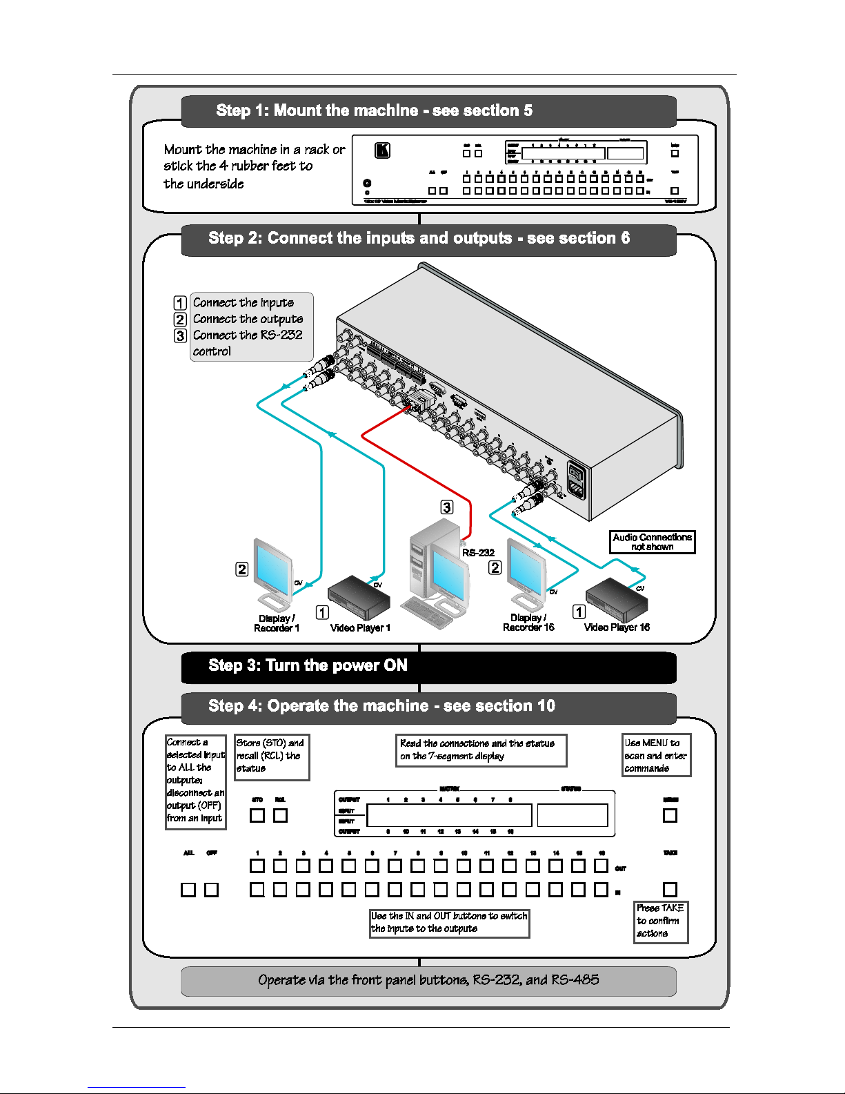
2.1 Quick Start
This quick start chart summarizes the basic setup and operation steps.
1 GROUP 1: Distribution Amplifiers; GROUP 2: Switchers and Matrix Switchers; GROUP 3: Control Syste ms; GROUP 4:
Format/Standards Converters; GROUP 5: Range Extenders and Repeaters; GROUP 6: Specialty AV Products; GROUP 7:
Scan Converters and Scalers; GROUP 8: Cables and Connectors; GROUP 9: Roo m Connectivity; GROUP 10: Accessories
and Rack Adapters; GROUP 11: Sierra Products
2 Download the latest software from our Web site at http://www.kramerelectronics.com
3 Download up-to-date Kramer user manuals from our Web site at http://www.kramerelectronics.com
Page 6
KRAMER: SIMPLE CREATIVE TECHNOLOGY
Getting Started
2
Page 7

Overview
3
3 Overview
The Kramer VS-162V is a high-performance 16x16 vertical interval matrix
switcher for composite video signals on BNC connectors. In addition to its
typical 16x16 operation, the VS-162V can be configured as follows:
• 8x8 for s-Video (Y/C)
• 5x5 for YUV or RGB (with the sync on the gr een signal - RG
S
B)
• 4x4 for RGBS signal s
A main advantage of the VS-162V is that it forms part of the series of
16x16 matrix switchers that includes, but is not limited to, VS-1616A (a
16x16 analog balanced stereo audio matrix switcher), VS-1616SDI (a
16x16 digital video matri x s wi tc her ), VS-1616AD (a 16x16 digit al audi o
matrix switcher), and VS-1616RS (an RS-422 control signal matrix
switcher).
In particular, the VS-162V:
• Produces glitch-free tr a nsitions, when sources share a common
reference sync
1
• Offers excellent video performance, which ensures that it remains
transparent in almost any video application
In addition the VS-162V:
• May be used as a single unit, or expanded to up to 96 x 96
inputs/outputs
• Can be configured into a Kramer multi-signal switcher system
including digita l and analog video, digita l and analog audio, and
RS-422 control switchers
• When integrated in a s ys tem, all units switch in true audio -follow-
video mode
• Recalls up to 99 configuration setups via the non-volatile memory
and provides for an unlimited quantity of se t ups when using the
Kramer control software on your PC
• Includes a user-friendly LCD displ ay (making operation even
easier)
• With its FLASH memory, lets you upgrade to the latest Kramer
firmware version via Internet download
• Comes with a choice of protocol format: hexadecimal or ASCII
1 As it switches during the vertical interval
Page 8

KRAMER: SIMPLE CREATIVE TECHNOLOGY
Your Video Matrix Switcher
4
You can control the VS-162V:
• Using the front pane l buttons
• Remotely, by RS-485 or RS-232 serial commands transmitted by
a touch screen system, PC, or other serial controller
• Remotely, from the Kramer RC-IR2 Infrared Remote Control
Transmitter
• An external remote IR receiver (optional), see section
4.1
• Via external dry-contact push buttons
To achieve the best performance:
• Connect only good quality connection cables, thus avoiding
interference, deterioration in signal quality due to poor matching,
and elevated noise levels (often associated with low quality
cables)
• Avoid interference from neighboring electrical appliances that
may adversely influence signal quality and position your Kramer
VS-162V in a location free from moisture and away from
excessive sunlight and dust
4 Your Video Matrix Switcher
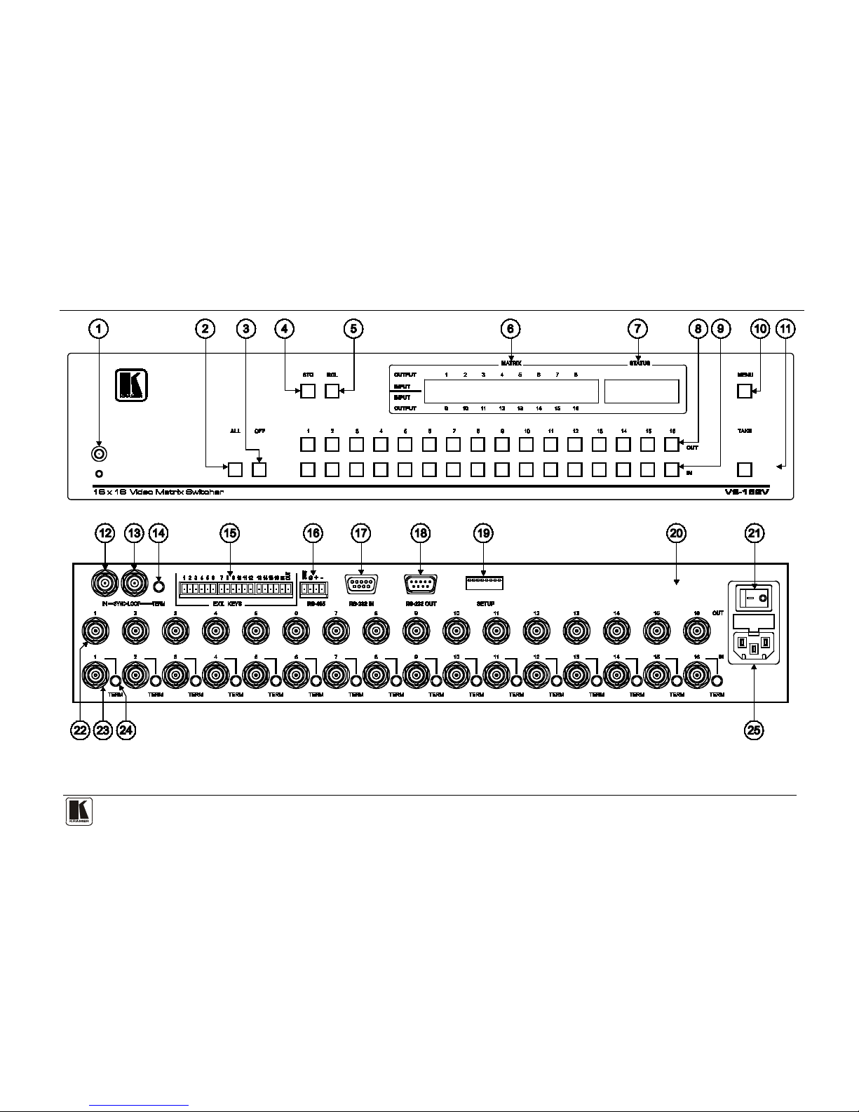
Figure 1 and Table 1 define the front and rear panels of the VS-162V.
Page 9
Your Video Matrix Switcher
5
Figure 1: VS-162V 16x16 Video M atrix Switcher
Page 10
KRAMER: SIMPLE CREATIVE TECHNOLOGY
Your Video Matrix Switcher
6
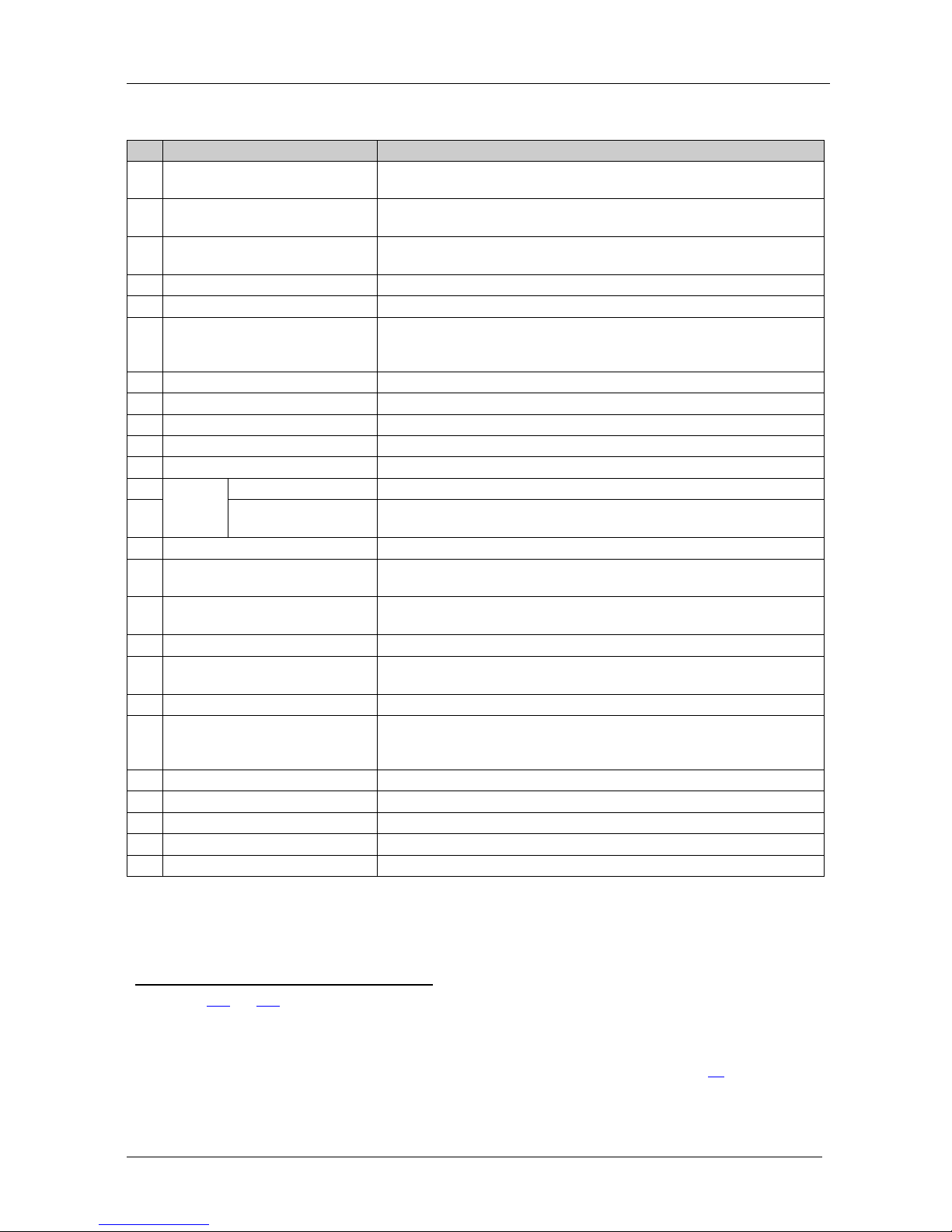
Table 1: Front Panel VS-162V 16x16 Video Matrix Switcher Features
#
Feature
Function
1 IR Receiver The red LED is illuminated when receiving signals from the Infrared
remote control transmitter
2 ALL Button Pressing ALL follo w ed b y an INPUT button, connects that input to
all outputs
3 OFF Button An OFF-OUT combination disconnects that output from the inputs; an
OFF-ALL combination disconnects all the outputs
4 STO Button Stores the current setting in the non-volatile memory
5 RCL Button Recalls a setup from the non-volatile memory
6 LCD MATRIX display
1
Displays the selected input(s) switched to the output(s) (above or
below the corresponding OUTPUT label) and user interface
messages
7 LCD STATUS Display1 Displays the matrix status
8 OUT Buttons Select the output to which the input is switched (from 1 to 16)
9 IN Buttons Select the input to switch to the output (from 1 to 16)
10 MENU Button Selects the programming commands to setup the switcher
11 TAKE Button Used to confirm and co mplete set up a nd sw itch ing
12
SYNC
IN BNC Connector Connects to the external video sync source
13 LOOP BNC
Connector
Connects to the SYNC IN connector on the next unit
14 TERM SYNC Button Press to terminate at 75Ω or release for looping
2
15 EXT. (extension) KEYS
Terminal Block Connectors
Connects to an external keyboard (remote unit)
16 RS-485 Detachable Terminal
Block Port
Pins # 1 and # 2 are for vertical sync and Ground connection, and
Pins # 3 and # 4 are for RS 485
17 RS-232 IN 9-pin D-sub (F) Port Connects to the PC or the Remote Controller
3
18 RS-232 OUT 9-pin D-sub (M)
Port
Connects to the RS-232 IN 9-pin D-sub port of the next unit in the
daisy-chain connection
19 SETUP DIP-Switches DIP-switches for setup of the unit
20 REMOTE IR 3.5mm Mini Jack Connect to an external IR recei v er unit for controlli ng th e machine
via an IR remote controll er (i ns tea d of us ing the front pa nel IR
receiver)
4
21 Power Switch Illuminated switch for turning the unit ON or OFF
22 OUT BNC Connectors Connect to the video acc eptors (from 1 to 16)
23 IN BNC Connectors Connect to the video sourc e s (from 1 to 16)
24 TERM IN Buttons Press to terminate at 75Ω or release for looping
5
25 Power Connector with Fuse AC connector enabling power supply to the unit
1 In sections 11.1 and 12.2 the word “Displays” refers to the LCD MATRIX and STATUS Displays
2 Push in to terminate the sync line. Push out when the sync line extends to another unit
3 If the unit is not the first unit in the line, connects to the RS-232 OUT 9-pin D-sub port of the previous unit in the line
4 Can be used instead of the front panel (built-in) IR receiver to remotely control the machine, see section
4.1
5 Push in to terminate the inp ut. Push out when the input extends to another unit (the last unit in the chain must be ter minated
when looping)
Page 11

Your Video Matrix Switcher
7 7
4.1 Usi n g th e IR Transmitter
You can use the RC-IR2 IR transmitter to control the machine via the builtin IR receiver on the front panel or, instead, via an optional external IR
receiver
1
. The external IR receiver can be located 15 meters away from the
machine. This distance can be extended to up to 60 meters when used with
three extension cables
2
Before using the external IR receiver, be sure to arrange for your Kramer
dealer to insert the internal IR connection cable
11F
3
with the 3.5mm connector
that fits into the REMOTE IR opening on the rear panel. Connect the
external IR receiver to the REMOTE IR 3.5mm connector.
1 Model: C-A35M/IRR-50
2 Model: C-A35M/A35F-50
3 P/N: 505-70434010-S
Page 12
KRAMER: SIMPLE CREATIVE TECHNOLOGY
Installing the VS-162V in a Rack
8
5 Installing the VS-162V in a Rack
.
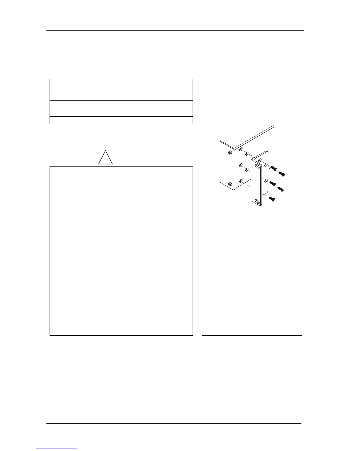
This section describes what to do before installing in a rack and how to rack
mount.
Before Installing in a Rack
How to Rack Mount
Before installing in a rack, be sure that the environment is
within the recommended range:
To rack-mount a machine:
1. Attach both ear brackets to the
machine. To do so, remove the
screws from each side of the
machine (3 on each side), and
replace those screws through the
ear brackets.
2. Place the ears of the machine
against the rack rails, and insert the
proper screws (not provided)
through each of the four holes in the
rack ears.
Note that:
• In some models, the front panel
may feature built-in rack ears
• Detachable rack ears can be
removed for desktop use
• Always mount the machine in the
rack before you attach any cables
or connect the machine to the
power
• If you are using a Kramer rack
adapter kit (for a machine that is not
19"), see the Rack Adapters user
manual for installation instructions
(you can download it at:
http://www.kramerelectronics.com
)
Operating temperature range +5º to +45º C (41º to 113º F)
Operating humidity range 10 to 90% RHL, non-condensing
Storage temperature range -20º to +70º C (-4º to 158º F)
Storage humidity range 5 to 95% RHL, non-condensing
!
CAUTION
!!
When installing in a 19" rack, avoid hazards by taking
care that:
1. It is located within the recommended environmental
conditions, as the op era ti ng ambi ent t e m pera tur e of a
closed or multi unit rack assembly may exceed the
room ambient temperature.
2. Once rack mounted, enough air will still flow around
the machine.
3. The machine is placed straight in the correct
horizontal positi on.
4. You do not overload the circuit(s). When connecting
the machine to the supply circuit, overloading the
circuits might have a detrimental effect on overcurrent
protection and supply wiring. Refer to t he app ro priate
nameplate ratings for information. For example, for
fuse replacemen t, s ee the value printed on the
product label.
5. The machine is earthed (grounded) in a reliable way
and is connected onl y to an ele ctric ity socket with
grounding. Pay particular attention to situations where
electricity is supplied indirectly (when the power cord
is not plugged directly into the socket in the wall), for
example, when using an extension cable or a power
strip, and that you use only the power cord that is
supplied with the machine.
Page 13
Installing and Operating a Single VS-162V - Overview
9 9
6 Installing and Operating a Single VS-162V - Overview
To install the VS-162V, connect the following
1
• Power cord
to the rear panel, as
required:
• Video input and output cables
• Control interface cables between switcher units, or PC (or other
controller), as described in section
9
• Set the DIP-switches, as described in section
8
• Set the system variables using the MENU function, as described
in section
11
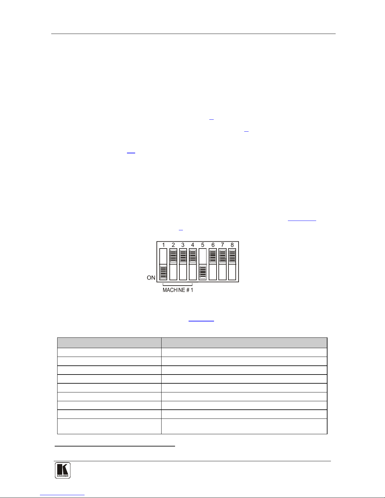
By default, the VS-162V is setup for operation as a single machine.
This means that it is:
• A 16x16 composite video switcher
• Switched during the vertical interval of the external reference
In particular, be sure that the DIP-switches are set as shown in
Figure 2 (for
more information, see section
8):
Figure 2: DIP-Switch Set u p on a Si n gl e Mac hine
To operate a single machine, s ee Table 2.
Table 2: Quick Reference Operating Guide for a Single Machine
To perform this command: Press:
Connect an input with an out put OUT #; IN #
Reset a specific output OUT #; OFF
Reset all outputs ALL; OFF
Connect all outputs to a specific input ALL; IN #
Store a setup STO; OUT #; TAKE
Recall a setup RCL; OUT #; TAKE
Lock front panel MENU; TAKE
Unlock front panel TAKE; TAKE
Change default setup Press the Menu button several times until you reach the
appropriate Menu s et up com m and and follow the instruc ti o ns
1 Switch OFF the power on each device before connecting it to your VS-162V
Page 14

KRAMER: SIMPLE CREATIVE TECHNOLOGY
Configuri ng the VS-162V Video Matrix Switcher
10
7 Configuring the VS-162V Video Matrix Switcher
Using the VS-162V unit a nd /or other 16x16 matrix switchers in the series
1
• A standalone switcher (see section
,
you can as semble the following kinds of systems:
7.1)
• A multi-channel video switcher (see section
7.2)
• An expanded matrix switcher (see section
7.3)
• A system of interconnected switchers (see section
7.4)
Note: When configuring multiple units , each unit must have an add ress. For
an explanation on addressing and system modes, see section 8
.
7.1 Configuring the Standalone VS-162V
This section describes ho w to configur e your VS-162V as a standalone
switcher for:
• Composite vid eo (CV) (see section
7.1.1)
• s-Video (Y/C) (see section
7.1.2)
• YUV (RGB) (see section
7.1.3)
• RGBS (see section
7.1.4)
Table 3 defines the number of inputs and outputs for each signal
configuration:
Table 3: Standalone Switcher Configuration for CV, Y/C, YUV (RGB) and RGBS
Configuration Number of Inputs and Outputs
on a Standalone Unit
Composite 16x16
s-Video (Y/C) 8x8
YUV / RGB 5x5
RGBS 4x4
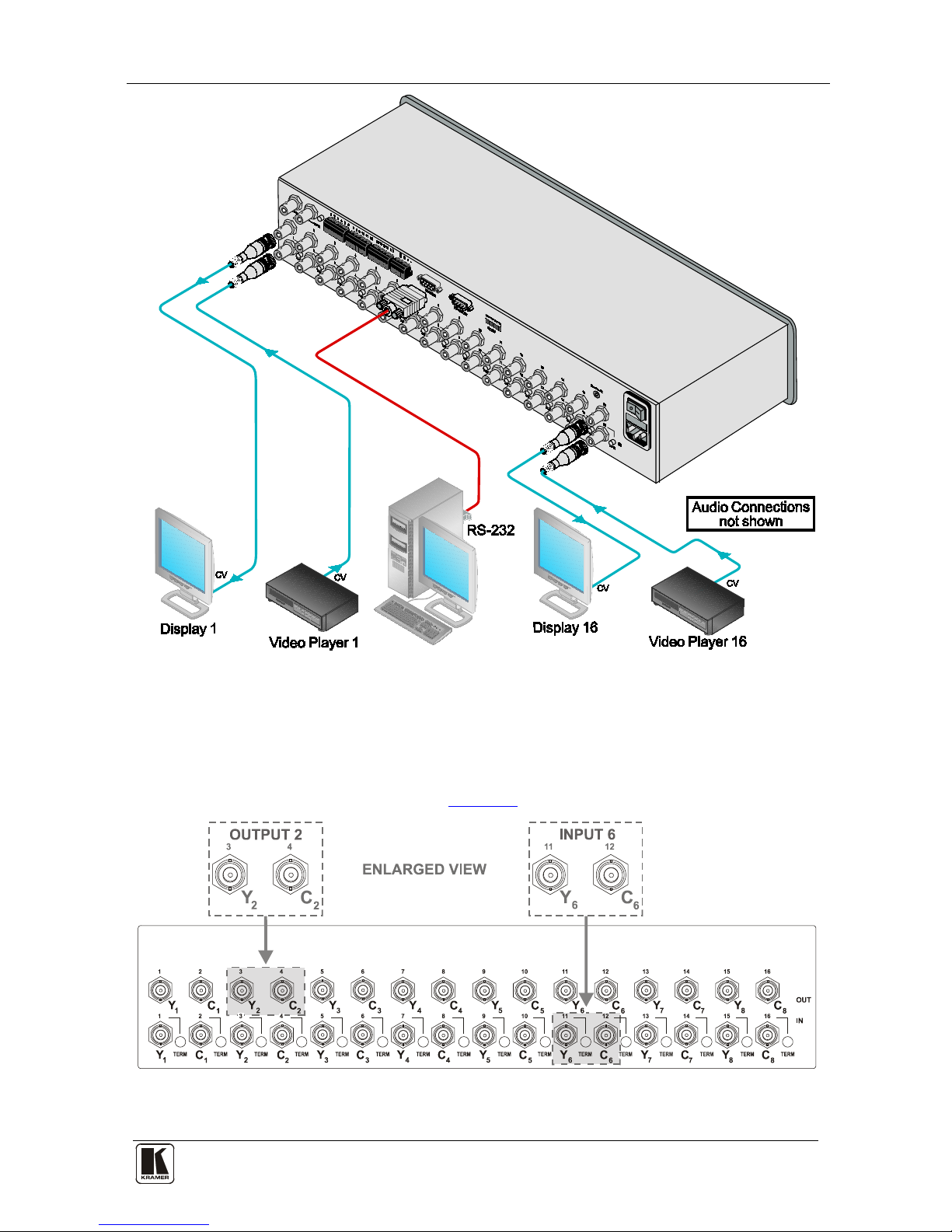
7.1.1 Configuring a 16x16 Composite Video Switcher
By default, a single VS-162V unit is configured for composite video with
16 inputs and 16 outputs, as shown in
Figure 3:
1 Including the V S-1616A (a 16x16 analog balanced stereo audio matrix switcher), the VS-1616SDI (a 16x16 digital video
matrix switcher), and the VS-1616AD (a 16x16 digital audio matrix switcher)
Page 15
Configuri ng the VS-162V Video Matrix Switcher
11 11
Figure 3: Configuring the VS-162V for Composite Video (CV)
7.1.2 Configuring an 8x8 s-Video (Y/C) Switcher
To configure a singl e VS-162V switcher as an 8x8 video matr ix switcher
(with 8 inputs and 8 outputs) for s-Video (Y/C), group the inputs and
outputs into pairs, as s hown in
Figure 4:
Figure 4: Configuring the VS-162V for s-Video (Y/C)
Page 16
KRAMER: SIMPLE CREATIVE TECHNOLOGY
Configuri ng the VS-162V Video Matrix Switcher
12
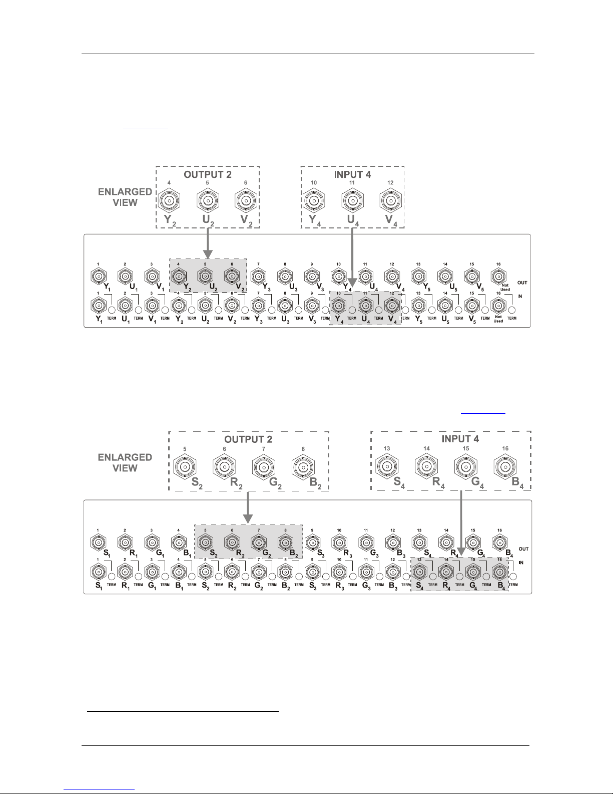
7.1.3 Configuring a 5x5 YUV/RGB Switcher
To configure a singl e VS-162V switcher as a 5x5 video matrix s witcher for
YUV (or RGB), group the inputs and outputs
1
Figure 5
into sets of 3, as shown in
. The YUV channel is also appropriate for RG
S
B. In this case,
connect Gs for Y, R for V and B for U.
Figure 5: Configuring the VS-162V for YUV (RGB)
7.1.4 Configuring a 4x4 RGBS Switcher
To configure a singl e VS-162V switcher as a 4x4 video matrix s witcher for
RGBS, group the inputs and outputs into sets of 4, as shown in
Figure 6:
Figure 6: Configuring the VS-162V for RGBS
1 Input 16 and output 16 are not used
Page 17
Configuri ng the VS-162V Video Matrix Switcher
13 13
7.2 Configuring 16x16 Multi-Channel Video Switchers
You can configure VS-162V units as a 16x16 multi-channel video switcher
for:
• s-Video (Y/C) (see section
7.2.1)
• YUV (RGB) (see section
7.2.2)
• RGBS (see section
7.2.3)
You may need several VS-162V units to expand the syste m, as
Table 4
defines. For example, for composite configuration, a single VS-162V unit
provides 16 inputs and 16 outputs. However, for s-Video (Y/C)
configuration you need two VS-162V units to provide 16 inputs and 16
outputs.
In a multi-channel video switcher configuration, one unit must be the master
(with DIP 6 OFF) while the other units are slaves (with DIP 6 ON).
The front panel of each slave unit is always locked and the MATRIX and
STATUS LCD displays do not illuminate . The slave units follow the master.
The master unit operates in the regular way
1
Note: To activate a mul ti-channel vid eo switcher so t hat each unit is in the
same state from the outset, turn on the master unit power before turning on
the slave units.
, leading t he slaves in the
background.
Table 4: 16x16 Multi-Channel Configurations
Configuration No. VS-162Vs Needed to
Make a 16x16 Switcher
Composite 1
s-Video (Y/C) 2
YUV / RGB 3
RGBS 4
7.2.1 Configuring a 2-Unit 16x16 Y/C Switcher
To configure a 16x16 s-Video (Y/C) video matrix switcher, combine two
VS-162V switchers. Connect as shown in Figure 7, substituting the C unit
for the U unit and ignorin g the V unit. Set the DIP-switches as shown in
Figure 7. Connect the communication line via the RS-232 or RS-485 control
interface as described in section 9.
1 The front panel is not locked and the MATRIX and STATUS LCD Displays illuminate
Page 18

KRAMER: SIMPLE CREATIVE TECHNOLOGY
Configuri ng the VS-162V Video Matrix Switcher
14
7.2.2 Configuring a 3-Unit 16x16 YUV/RGB Switcher
To configure a 16x16 YUV video matrix switcher, combine
1
Figure 7
three
VS-162V switchers, as shown in :
Figure 7: Configuring a 16x16 YUV (RGB) Switcher with 3 VS-162V Units
1 For a description of how to connect the RS-485 connectors between the VS-162V switchers, refer to section 9.2
Page 19

Configuri ng the VS-162V Video Matrix Switcher
15 15
7.2.3 Configuring a 4-Unit 16x16 RGB S Switcher
To configure four VS-162V switchers as a 16x16 RGBS video matrix
switcher, combine three VS-162V switchers for YUV (RGB) as shown in
Figure 7.
7.3 Configuring a Multi-Unit Matrix Switcher
You can greatly expand the number o f inputs and outp uts using several VS162V units
1
8.3
. To do this, you must set a unique MACHINE ADDRESS #
(see section ) on each VS-162V unit. This defines which inputs and
outputs are configured to a particular unit, as the chart in
Figure 8
illustrates.
For example, to connect a 48x64 switcher (48 inputs and 64 outputs), you
would configure using MACHINE ADDRESS # 1, 2, 3, 4; 7, 8, 9, 10; 13,
14, 15 and 16. You can only choose a rectangular
2
Figure 8
configuration from the
chart in .
OUTPUTS 1-16 OUTPUTS 65-80OUTPUTS 49-64OUTPUTS 17-32
INPUTS
17-32
INPUTS
1-16
INPUTS
33-48
INPUTS
49-64
INPUTS
65-80
MACHINE
ADDRESS # 7
MACHINE
ADDRESS # 1
MACHINE
ADDRESS # 13
MACHINE
ADDRESS # 19
MACHINE
ADDRESS # 25
MACHINE
ADDRESS # 31
MACHINE
ADDRESS # 8
MACHINE
ADDRESS # 2
MACHINE
ADDRESS # 14
MACHINE
ADDRESS # 20
MACHINE
ADDRESS # 26
MACHINE
ADDRESS # 32
INPUTS
81-96
OUTPUTS 33-48
MACHINE
ADDRESS # 9
MACHINE
ADDRESS # 3
MACHINE
ADDRESS # 15
MACHINE
ADDRESS # 21
MACHINE
ADDRESS # 27
MACHINE
ADDRESS # 33
MACHINE
ADDRESS # 10
MACHINE
ADDRESS # 4
MACHINE
ADDRESS # 16
MACHINE
ADDRESS # 22
MACHINE
ADDRESS # 28
MACHINE
ADDRESS # 34
MACHINE
ADDRESS # 11
MACHINE
ADDRESS # 5
MACHINE
ADDRESS # 17
MACHINE
ADDRESS # 23
MACHINE
ADDRESS # 29
MACHINE
ADDRESS # 35
OUTPUTS 81-96
MACHINE
ADDRESS # 12
MACHINE
ADDRESS # 6
MACHINE
ADDRESS # 18
MACHINE
ADDRESS # 24
MACHINE
ADDRESS # 30
MACHINE
ADDRESS # 36
Figure 8: MACHINE ADDRESS # Designation
1 For example, a 32x32 switcher and a 32x16 switcher. In fact, you can connect up to 36 u nits to form a switcher with 96
inputs and 96 outputs
2 For example, like this:
but not like this:
Page 20
KRAMER: SIMPLE CREATIVE TECHNOLOGY
Configuri ng the VS-162V Video Matrix Switcher
16
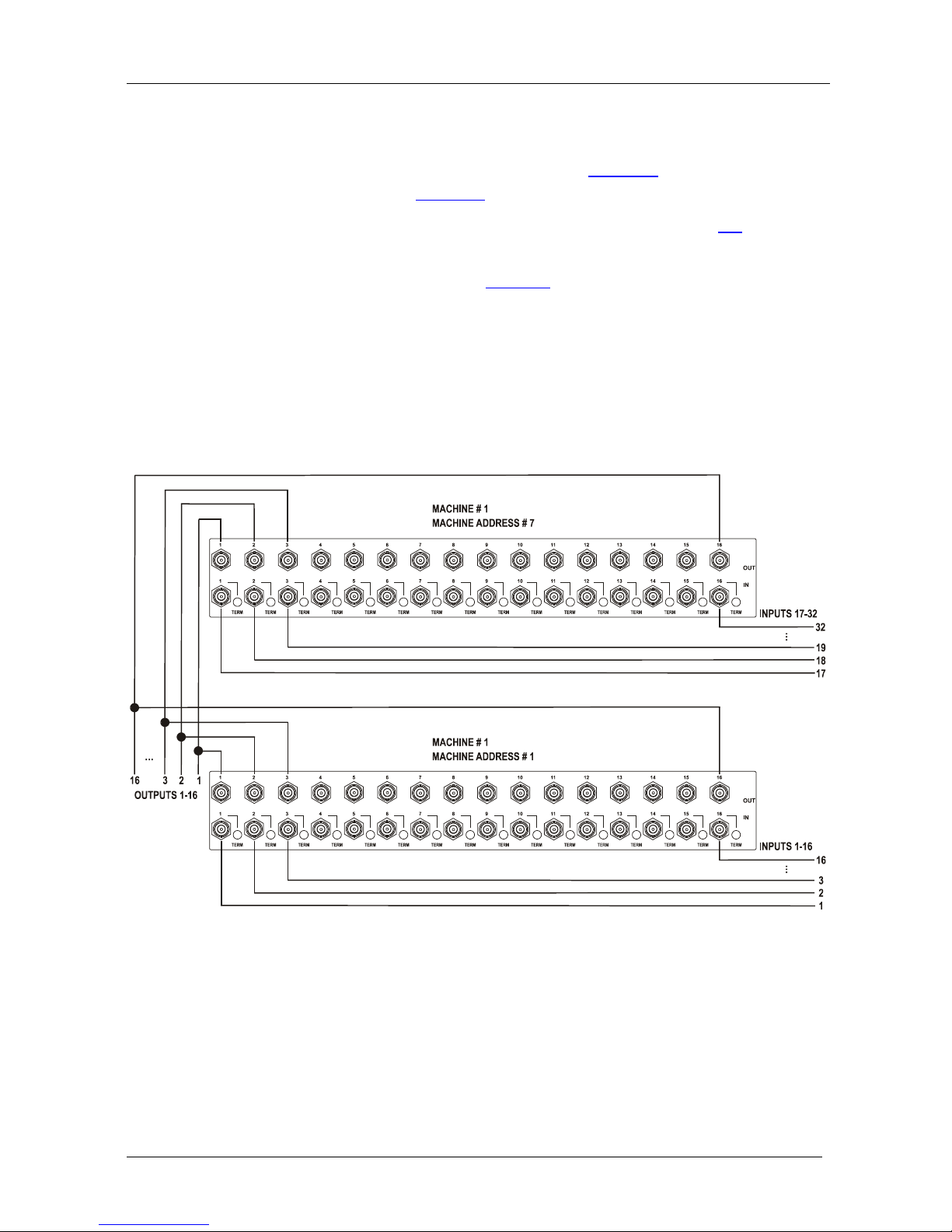
7.3.1 Configuring a 32x16 Switcher
A 32x16 switcher co nsists of two VS-162V units (MACHINE ADDRESS #
1 and MACHINE ADDRESS # 7), a s s hown in
Figure 8. To make this
configuration, as shown in
Figure 9:
1. Set the MACHINE # on both VS-162V units to #1 (see section
8.2).
2. Set the MACHINE ADDRESS # on one VS-162V unit to 1 and on the
other VS-162V unit to 7 (refer to
Figure 8).
3. Set DIP 6 OFF on both VS-162V units.
4. Using T-connectors, connect OUTPUTS 1 to 16 on both VS-162V units.
OUTPUTS 1 to 16 become the SYSTEM OUTPUTS 1 to 16, while the
inputs on the MACHINE ADDRESS # 1 are system inputs 1 to 16, and the
inputs on the MACHINE ADDRESS # 7 are system inputs 17 to 32.
The two VS-162V units form a 32x16 switcher.
Figure 9: Conf i gur ing a 32x16 Sw it c he r
Page 21

Configuri ng the VS-162V Video Matrix Switcher
17 17
7.3.2 Configuring a 32x32 Switcher
As shown in Figure 8, a 32x32 switcher consists of four VS-162V units
(MACHINE ADDRESS # 1, MACHINE ADDRESS # 2, MACHINE
ADDRESS # 7 and MACHINE ADDRESS # 8). To assemble, as shown in
Figure 10:
1. Set the same MACHINE #
1
2. Set the MACHINE ADDRESS # to 1, 2, 7 and 8 on each of the four units,
respectively (refer to
on all the four VS-162V units.
Figure 8).
3. Set DIP 6 OFF on each of the four VS-162V units.
4. Using T-connectors, connect INPUTS 1 to 16 on the VS-162V unit
designated as MACHINE ADDRESS # 2 with INPUTS 1 to 16 on the VS-
162V unit designated as MACHINE ADDRESS # 1.
5. Terminate the INPUTS on MACHINE ADDRESS # 2 to 75Ω (push in the
TERM button
2
6. Using T-connectors, connect INPUTS 17 to 32 on the VS-162V unit
designated as MACHINE ADDRESS # 8 with INPUTS 17 to 32 on the
VS-162V unit designated as MACHINE ADDRESS # 7.
next to the INPUT BNCs) and put the inputs in MACHINE
ADDRESS # 1 int o Hi-Z state (release the TERM buttons next to the
INPUT BNCs).
INPUTS 1 to 16 become the SYSTEM INPUTS 1 to 16.
7. Terminate the INPUTS on MACHINE ADDRESS # 8 to 75 Ω (push in the
TERM button next to the INPUT BNCs) and put the inputs in MACHINE
ADDRESS # 7 int o Hi-Z state (release the TERM buttons next to the
INPUT BNCs).
INPUTS 17 to 32 become the SYSTEM INPUTS 17 to 32.
8. Using T-connectors, connect OUTPUTS 1 to 16 on the VS-162V unit
designated as MACHINE ADDRESS # 7 with OUTPUTS 1 to 16 on the
VS-162V unit designated as MACHINE ADDRESS # 1.
OUTPUTS 1 to 16 become the SYSTEM OUTPUTS 1 to 16.
9. Using T-connectors, connect OUTPUTS 17 to 32 on the VS-162V unit
designat e d as MAC HINE ADD RESS # 8 with OUTPUTS 17 to 32 on the
VS-162V unit designated as MACHINE ADDRESS # 2.
OUTPUTS 17 to 32 become the SYSTEM OUTPUTS 17 to 32.
The 4 VS-162V units form a 32x32 switcher.
1 Set to # 1 in most cases. In the example in Figure 10, the MACHINE # is set to # 2
2 Item 10 on the rear panel in
Figure 1
Page 22

KRAMER: SIMPLE CREATIVE TECHNOLOGY
Configuri ng the VS-162V Video Matrix Switcher
18
Figure 10: C on ne c t ing the 32x32 Switc he r
7.4 Configuring a System of Interconnected Switchers
A majo r advantage of the VS-162V is that it belongs to the series of 16x16
matrix switchers that can interconnect with other switchers in the series.
This series includes, but is not limited to, VS-1616A (a 16x16 analog
balanced stereo audio matrix switcher), VS-1616SDI (a 16x16 digital video
matrix switcher), VS-1616AD (a 16x16 digital audio matrix switcher), a nd
VS-1616RS (an RS-422 control signal matrix switcher).
The block diagram in
Figure 11 illustrates how to assemble an
interconnected varied-format 16x16 series switcher that consists of a 32x32
composite video matrix swi tcher, a 32x16 d igital vide o matrix switcher, a
32x32 balanced stereo audio matrix switcher, and a 16x16 digital audio
matrix switcher.
Note that each group of switchers has a unique MACHINE # that is shared
by all members of the group. In
Figure 11, the 32x32 composite video
matrix switcher is MACHINE # 1, the 32x16 digital video matrix switcher
is MACHINE # 2 and so on. Control of the system is via the MACHINE #s.
Page 23

Configuri ng the VS-162V Video Matrix Switcher
19 19
Figure 11: Assembling a System of Interconnected Switchers
Refer to section 8.1 for how to set the DIP-switches, and to section 9 for
how to control this group of interconnected varied-format 16x16 series
switchers, and other configurati ons.
Page 24

KRAMER: SIMPLE CREATIVE TECHNOLOGY
Understanding Addressing and System Modes
20
8 Understanding Addressing and System Modes
In order to control multiple machines, the VS-162V uses a system of
addressing that includes hardware DIP-switches and menu commands. The
DIP-switches are used to set the MACHINE# and menu commands are used
to set the MACHINE ADDRESS #. Note the following:
• A standalone machine is always set to MACHINE# 1
• When configuring multiple VS-162V units or a matrix of VS-162V
machines, the array is viewed as one large unit and the DIP-switches
of all machines are set to the same MACHINE#. However, each
machine is set to a unique MACHINE ADDRESS # with a menu
command on its display panel according to the addressing rule shown
in
Figure 8
• When configuring a mix of different model machines, each group of
models receives a different MACHINE# and each machine is set to a
unique MACHINE ADDRESS # (see section
7.4).
8.1 Se tting the DIP-Switches
Configur e the VS-162V by setting the 8 DIP-switches as
Figure 12 and
Table 5 define:
Figure 12: Re ar P ane l DIP-switches
Table 5: DIP-switch Definitions
DIP-switch #
Function:
1-4 Set the MACHINE # (see Table 6 in section 8.2)
5 Enables (ON) or disables (OFF) the Follow-SYSTEM mode
6 Enables (ON) or disables (OFF) the SLAVE mode in a multi-channel configuration
7 Disables use of a null-modem adapter
1
OFF = RS-232 connection via a null-modem adapter
ON = RS-232 connecti on wi th out a null-modem adapter
with RS-232
8 RS-485 termination for first and last machine = ON (RS-485 line terminates with
110Ω); for others = OFF (RS-485 line is open)
1 See section 9.1
Page 25

Understanding Addressing and System Modes
21 21
8.2 Se tting the MACHINE #
To control a unit via RS-232 or RS-485, each unit must be identified via its
unique MACHINE #. In an extended matrix configuration, in addition to
the MACHINE #, each unit is identified via its MACHINE AD D RESS #.
Set the MACHINE #
1
Table 6 on a VS-162V unit according to .
A valid MACHINE # is from 1 to 15. 0 is not a valid address.
Table 6: Machi ne # DIP-Switch Settings
MACHINE #
DIP-SWITCH
MACHINE #
DIP-SWITCH
1 2 3 4 1 2 3 4
1
ON
OFF OFF OFF 9
ON
OFF OFF
ON
2 OFF
ON
OFF OFF 10 OFF
ON
OFF
ON
3
ON ON
OFF OFF 11
ON ON
OFF
ON
4 OFF OFF
ON
OFF 12 OFF OFF
ON ON
5
ON
OFF
ON
OFF 13
ON
OFF
ON ON
6 OFF
ON ON
OFF 14 OFF
ON ON ON
7
ON ON ON
OFF 15
ON ON ON ON
8 OFF OFF OFF
ON
8.3 Se tting the MACHINE ADDRESS #
The MACHINE ADDRESS # is determined via the MACHINE ADDRESS
Menu command, as section
11.4 describes. The MACHINE ADDRESS #
defines which inp uts and out puts are configured to that particular unit when
expanding, as the chart in
Figure 8 illustrates.
A valid MACHINE ADDRESS # is from 1 to 36.
8.4 Understanding the SYSTEM Mode
DIP-switch 5 define s whether the VS-162V unit communic ates with other
switchers via a common co ntrol line.
You can set DIP 5 OFF to disable the Follow-SYSTEM mode in t he
following applications:
• Standalone switcher applic a tions
2
• A multi-channel video switcher application
3
• An expanded matrix switcher application
4
1 When using a single unit, set the unit to MACHINE # 1
2 See section 7.1
3 See section
7.2
4 See section
7.3
Page 26

KRAMER: SIMPLE CREATIVE TECHNOLOGY
Connecting a Control Interface
22
You must set DIP 5 ON to enable the Follow-SYSTEM mode in an
interconnected varied-format switcher application
1
For a description of the Follow-SYSTEM and Breakaway-from-SYSTEM
menu modes, see section
11.2
.
8.5 Understanding the SLAVE Mode
The SLAVE mode is only used for the multi-channel video switcher
configuration
2
Figure 7
, for example, whe n using three VS-162V units to form a
YUV switcher, as shown in .
One unit i s used as the master, and the other two units are slaves. The slaves
always foll o w the master. In the example shown in
Figure 7, the first
VS-162V unit is the master (with DIP 6 set OFF disabling the slave mode)
and the sec ond and third VS-162V units are slaves (with DIP 6 set ON
enabling the slave mode).
On both slave VS-162V units, the MAT RIX a nd STATUS Displays do not
illuminate and the STAT US Display shows the following message:
Keyboard LOCKED
However , the STATUS Display on each slave VS-162V unit dynamical l y
shows
3
Front panel control is via t he master VS-162V unit, on which t he front p anel
buttons are unlocked and both the MATRIX and S TATUS displays
illuminate.
all changes made from the master VS-162V unit.
9 Connecting a Control Interface
Connect a control interface (RS-232 or RS-485) unless operating a
VS-162V as a standalone unit without any contro l device (that is, with
control fro m the front panel or IR port, and not via a remote controller or a
PC).
The control interface must be identical on each switcher in the series of
16x16 matrix switchers; ei ther RS-232 or RS-485. One control interface
suffices. Do not use both RS-232 and RS-485 control interfaces in the sa me
configuration. For exa mple, in an interconnected varied-format 16x16
switcher application
1
, if the switcher that connects to the PC connects via
1 See section 7.4
2 See section
7.2
3 Albeit with an LCD Display that does not illuminate
Page 27

Connecting a Control Interface
23 23
the RS-232 control interface, each switcher must interconnect via the
RS-232 control interface and not via the RS-485 control interface.
Choose t he RS-232 control interface for a point-to-point connection with a
range of about 25 meters.
Choose t he RS-485 control interface to operate the switcher from an
extended distance of up to 1000 meters.
9.1 Connecting the RS-232 Control Interface
Connect several switchers (from the series of 16x1 6 matrix switchers) and
the control unit i n an RS-232 daisy chain arrangement, with or without
using a null-modem adapter, as shown in
Figure 13
.
The RS-232 daisy cha in switcher arrangeme nt is transparent. This lets you
arrange the switchers (from the series of 16x16 matrix switchers) according
to your require ments, and not according to a fixed sequence dependent on
the MACHINE # and/or MACHINE ADDRESS #.
Figure 13: Connecting a PC to 4 VS-162V Units
Page 28

KRAMER: SIMPLE CREATIVE TECHNOLOGY
Connecting a Control Interface
24
You can connect any of the following:
• Two VS-162V units, u sing a null-modem adapter (see section
9.1.1) or without using a null-modem adapter (see section 9.1.2)
• The 9-pin D-sub COM port of a PC to a VS-162V unit wit h a
null-modem adapter (see section
9.1.3) or without a null-modem
adapter (see section
9.1.4)
• The 25-pin D-sub COM port of a PC to a VS-162V unit with a
null-modem adapter (see section
9.1.5) or without a null-modem
adapter (see section
9.1.6)
9.1.1 Connecting Two Units with a Null-Modem Adapter
To connect two VS-162V units, using a null-modem ada pter provided
with the machine ( default):
1. Connect a flat cable
1
2. On the second VS-162V unit, set DIP 7 OFF (enabling null-modem
adapter use).
betw een th e RS-232 OUT 9-pin D-sub port on the first
VS-162V unit and the null-m odem adapter t hat att aches to the RS -232 IN 9-
pin D-sub port on the second VS-162V unit.
9.1.2 Connecting Two Units without a Null-Modem Adapter
To connect two VS-162V units, without u s ing a null-modem adapter:
1. Connect a flat cable
1
between the RS-232 OUT 9-pin D-sub port on th e fi rst
VS-162V unit and the RS-232 IN 9-pin D-sub port on the second VS-162V
unit.
2. On the second VS-162V unit, set DIP 7 ON (disabling null-modem adapter
use
2
9.1.3 Connecting to a 9-pin PC COM Port with a Null-Modem A dapter
).
To connect the 9-pin D-sub COM port of a PC to a VS-162V unit, using a
null-modem adapter:
1. Connect a flat cable
1
between the 9-pin D-sub COM port of the PC and the
null-modem adapter that attaches to the RS-232 IN 9-pin D-sub port on the
VS-162V unit.
2. Set DIP 7 OFF (enabling null-mod em a da pt er u s e
2
) on the VS-162V unit.
1 Straight one-to-one uncrossed connections with at least the 3 wires pins # 2, # 3 and # 5
2 See section 8
Page 29

Connecting a Control Interface
25 25
9.1.4 Connecting to a 9-pin PC COM Port without a Null-Modem
Adapter
To connect the 9-pin D-sub COM port of a PC to a VS-162V unit, without
using a null-modem adapter:
1. Connect a flat cable
1
2. Set DIP 7 ON (disabling null-modem adapter use
betw een th e 9-pin D-sub COM port of the PC and the
RS-232 IN 9-pin D-sub port on the VS-162V unit.
2
9.1.5 Connecting to a 25-pin PC COM Port with a Null-Modem Adapt er
) on the VS-162V
unit.
To connect the 25-pin D-sub COM port of a PC to a VS-162V unit, using a
null-modem adapter:
1. Connect a flat cable
1
between the 25-pin D-sub COM por t an d the null-
modem a dapt er th at a ttach es to the RS -232 IN 9-pin D-sub port on the first
VS-162V unit.
2. Set DIP 7 OFF (enabling null-modem a dapter us e
2
) on the VS-162V
unit.
9.1.6 Connecting to a 25-pin PC COM Port without a Null-Modem
Adapter
To connect the 25-pin D-sub COM port of a PC to a VS-162V unit, without
using a null-modem adapter:
1. Connect the 25-pin D-sub COM port to the RS-232 IN 9-pin D-sub port on
the VS-162V unit, as
Figure 14 illustrates:
Female DB25 (From PC)
PIN 20 connected to PIN 6
Connect PINS 4, 5 and 8 together
Figure 14: Connecting to a 25-pin PC COM Port without a Null-Modem Adapter
1 Straight one-to-one uncrossed connections with at least the 3 wires pins # 2, # 3 and # 5
2 See section 8
Page 30

KRAMER: SIMPLE CREATIVE TECHNOLOGY
Connecting a Control Interface
26
2. Set DIP 7 ON (disabling null-modem adapter use
1
9.2 Connecting the RS-485 Control Interface
) on the VS-162V unit.
Figure 15 defines the RS-485 connector pinout for external RS-485 control.
The RS-485 connector is also used (if required) for vertical sync:
Figure 15: RS-48 5 Co nne c tor P INOUT
To connect an RS-485 connector on one VS-162V unit to an RS-485
connector on one or more other switchers (from the series of 16x16 matrix
switchers), as
Figure 16 illustrates:
1. Connect the “+” PIN on the first VS-162V unit to the “+” PIN on the
second VS-162V unit or other unit
2. Connect the “-” PIN on the first VS-162V unit t o the “-” PIN on the second
VS-162V unit or other unit
3. If shielded cable is used for an RS-485 connection, connect the shield to the
Ground PIN.
For details about how to configure the vertical sync (if required), refer to
section
9.3 and Figure 21 in section 11.5.1.
1 See section 8
Page 31

Connecting a Control Interface
27 27
Figure 16: Connecting the RS-485 Connector s be t we e n Two VS-162V Units
Figure 17 illustrates the RS-485 line that connects:
• Between each VS-162V unit
• To the PC via a Kra mer Too ls VP-43xl Interface Converter
(connect the 9-pin D-sub PC COM port to the “RS-232 in” 9-pin
D-sub port on the VP-43xl. Next, connect the RS-485 port on the
VP-43xl to the RS-485 ports on the VS-162V units)
Page 32

KRAMER: SIMPLE CREATIVE TECHNOLOGY
Connecting a Control Interface
28
Figure 17: An RS-485 Control Interface Setup
Page 33

Connecting a Control Interface
29 29
9.3 Configuring the Sync
On the VS-162V, you can select one of the follo wing, as the sync input:
• EXTERNAL (“sync in” BNC connector)
• INPUT # 1 BNC connector
• MTX (Sync from Matrix) RS-485 terminal block connector, when
using multiple machines
1
Configur e the sync via the SWITCHING METHOD menu command
setting
2
Usually, the easiest method is to choose the sync source from the first
machine (for example, the Y unit in a 16x16 YUV switcher configuration,
as section
. When se tting up multiple machines (for example, a 48x64
switcher) or a 16x16 YUV switcher, linking a common sync to all the
machines may be necessary to facilitate simultaneous vertical interval
switching.
7.2.2 describes) and then connect all the terminal block
connectors, as
Figure 7 illustrates.
In this case, set the first machine to select the sync source from the external
sync connector or from the INPUT # 1 connector. This sync is now
available to the other machines via the RS-485 terminal block connector, as
Figure 15 and Figure 16 illustrate. Select the MTX sync on the other
machines that receive that sync.
9.4 Connecting the KEYBOARD EXTENSION
Connecting dry co ntact-closure switches to the Keyboard Extension (EXT.
KEYS) connector enables you to route an input to an output by remote
control from a distance of up to 1000 meters. These IN and OUT keys are
expandable
3
Figure 18. shows how to connect the Keyboard Extension
(EXT. KEYS):
1 Refer to section 11.5.1
2 Refer to section
11.5
3 Add an unlimited number of push buttons to the existing keys (in parallel) by attaching one end of the push button to the
corresponding number and the other end to the IN or OUT
Page 34

KRAMER: SIMPLE CREATIVE TECHNOLOGY
Operating Your Video Matrix Switcher
30
Figure 18: Keyboard Extension (EXT. KEYS) Connector
To use the K eyboard Extension, activate the extended KEYB O A RD setting
Menu command, as section
11.6 describes.
10 Operating Your Video Matrix Switcher
You can oper ate your VS-162V using:
• The front panel buttons (as this section describes)
• RS-232 or RS-485 serial commands transmitted by a touch screen
system, P C
1
• The Kramer RC-IR2 Infrared Remote Control Tra nsmitter
, or other serial controller
• Dry contact-closure switches connected to the keyboard extension
10.1 Startup Display
After switching on the power, the MATRIX and STATUS
2
1 For instructions on usin g Kramer Win dows 95/98/NT TM Control Software, refer to the separate user manual (included on
the CD-ROM in .pdf format), Kramer Control Software
displays show the
following scree ns in seque nce:
2 Version 1.5 is shown in the Status Display as an example; text in the Matrix Display may vary (according to machine
settings)
Page 35

Operating Your Video Matrix Switcher
31 31
Figure 19: Default Startup Status Display Sequence
10.2 Using the Front Panel Buttons
You can switch (see section
10.4) and clear (see section 10.5):
• One input to one output
• Several inputs to several outputs
• One input to all outputs
Choose to work in the AT ONCE mode or the CONFIRM mode:
In the AT ONCE (default
1
• Actions require no user confirmation
) mo de:
• Execution is immediate
• No protection is offered against changing an action in error
In the CONFIRM mode
2
• You have an optional method to help avoid making a mistake
:
• Every action requires user confirmation
• Execution is delayed
3
• Protection is offered to prevent erroneous switching
until the user confirms the ac tion
• You can key-in several actio ns and then confirm them b y pressing
the TAKE button once, to simultaneously switch several monitors
1 For all actions except storing/recalling setups
2 The CONFIRM mode is the default for storing/recalling setups (see section
10.6)
3 Failure to press the TAKE button within 30 seconds to one minute (the Timeout) will abort the action
Page 36

KRAMER: SIMPLE CREATIVE TECHNOLOGY
Operating Your Video Matrix Switcher
32
10.3 Toggling Between the AT ONCE and CONFIRM Modes
To toggle between the AT ONCE (default) mode and the CONFIRM mode,
press the TAKE button.
In CONFIRM mode: Actions require user confirmation and the TAKE LED
lights.
In AT ONCE mode: Actions d o not require user c onfirmation and the
TAKE LED does not light.
When the TAKE LED flashes:
• You cannot toggle between the AT ONCE and CONFIRM modes
• You can execute the previous action, by pressing the TAKE
button
• You can cancel the previous action, by pressing a non-relevant
button (for example, the MENU button)
10.4 Switching
You can switch:
• One input to one output (see section
10.4.1)
• Several inputs to several outputs (see section
10.4.2)
• One input to all outputs (see section
10.4.3)
10.4.1 Switching One Input to One Output
Pressing an OUT-IN co mbi na t io n whe n yo ur VS-162V operates in the AT
ONCE mode implements the s witch immediately.
To switch one input to one output (AT ONCE mode ):
1. Press the appropriate OUT button.
The MATRIX display shows the two flashing digits, representing the
present input number connected to that specific output
1
out # x
. If the present
output is clear, the two flashing digits 00 appear in the MATRIX display.
The STATUS Display shows the message:
Where x is the output number
2. Press the appropriate IN button.
The output sw itches t o the in put and the MATRIX display shows the Input
# instead of the flashing digits.
The STATUS Display momentarily sh ows the message:
1 For example, pressing OUT button 9 shows the flashing digits 01 if input 1 was previously routed to OUT 9
Page 37

Operating Your Video Matrix Switcher
33 33
out # x
from in # y
Where x is the output number and y is the input number
Pressing an OUT-IN co mbi na t io n whe n yo ur VS-162V operates in the
CONFIRM mode (and the T A K E LED is lit), requires user co nfir mation.
To switch one input to one output (CONFIRM mode):
1. Repeat step 1 above.
2. Press the appropriate IN button.
The MATRIX display shows the two flashing digits, representing the input
number and the TAKE LED flashes.
The STATUS Display shows
1
out # x
from in # y
the message:
Where x is the output number and y is the input number
3. Press the TAKE button to confirm the action.
The output sw itches t o the in put and the TAKE L ED l ights.
10.4.2 Switching Several Inputs to Several Outputs
In the AT ONCE mode, you need to execute each OUT-IN combination
separately (see section
10.4.1). When switc hing many inputs to many
outputs it is recommended to toggle to the CONFIRM mode.
In the CON F IRM mod e you can key-in several actions and then confirm
them by pressing t he TAKE button once (simultaneou s ly switc hing sever al
inputs to several outputs).
To switch s everal i nputs to several outputs in the CONFIRM mode (the
TAKE LED is lit), do the foll owing:
1. Press the appropriate OUT button.
The MATRIX display shows the two flashing digits, representing the
previous input number for that specific output
2
out # x
. If the previous input is clear,
the two flashing digits 00 appear in the MATRIX display.
The STATUS Display shows the message:
Where x is the output number
1 Continuously, within the limit of the timeout (approximately 30 seconds to one minute)
2 For example, pressing OUT button 9 shows the flashing digits 01 if input 1 was previously routed to OUT 9
Page 38

KRAMER: SIMPLE CREATIVE TECHNOLOGY
Operating Your Video Matrix Switcher
34
2. Press the appropriate IN button.
The MATRIX display shows the two flashing digits, representing the input
number and the TAKE LED flashes.
The STATUS Display shows
1
out # x
from in # y
the message:
Where x is the output number and y is the input number
3. Press the second appropriate OUT button, repeating step 1 above.
4. Press the appropriate
2
5. Continue with this OUT-IN button sequence, pressing the appropriate
OUT and IN buttons, as required. You can also combine an OUT-OFF
or OFF-OUT combinat ion w ith th is se quenc e.
IN button, repeating step 2 above.
6. After completing the sequence, press the TAKE button to confirm the
actions.
The inputs switch to the respectiv e outputs , as the MATRIX display shows
(no digits flash) and the TAKE LED lights.
10.4.3 Switching One Input to All Outputs
To switch one input to all the outputs (in the AT ONCE mode):
1. Press the ALL button.
The MATRIX display shows all the s ets of two flashing digits (each
representing the present input number for that respective output) flashing
simultaneously.
The STATUS Display shows the message:
all OUTs
2. Press the appropriate IN button.
This input sw itches t o all the outputs an d the MATRIX display shows the
identical non-flashing two digits (representing that input number).
To switch one input to all the outputs (in the CONFIRM mode, (the
TAKE LED is lit)):
1. Repeat steps 1 and 2 above.
The TAKE LED flashes.
2. Press the TAKE button to confirm the action.
The selected input sw itches to all th e out puts and th e TAKE LED lig hts.
The MATRIX display shows the identical two non-flashing digits
(representing that input number) for all outputs.
1 Continuously, within the limit of the timeout (approximately 30 seconds to one minute)
2 That corresponds with the second OUT button
Page 39

Operating Your Video Matrix Switcher
35 35
10.5 Clearing
1
You can clear (delete):
• One output (see section
10.5.1)
• Several outputs (see section
10.5.2)
• All outputs (see section
10.5.3)
10.5.1 Clearing an Output
To clear an output (in the AT ONCE mode):
1. Press the appropriate OUT button.
The MATRIX display shows the two flashing digits, representing the
present input number for that specific output
2
out # x
. If the present input is clear,
the two flashing digits 00 appear in the MATRIX display.
The STATUS Display shows the message:
Where x is the output number
2. Press the OFF button
3
out # x
reset
.
The in put is clea red an d th e MATRIX display does not show any Input # in
its place.
The STATUS Display momentarily shows the message:
Where x is the output number
To clear an output (in the CONFIRM mode (the TAKE LED is lit) ) :
1. Repeat step 1 above.
2. Press the OFF button
3
.
The MATRIX display shows the two flashing digits 00 instead of the
previous two flashing digits and the TAKE LED flashes.
The STATUS Display shows
4
out # x
reset
the message:
Where x is the output number
1 “Clearing” means disconnecting the output from any of the inputs, and leaving it disconnected
2 For example, pressing OUT button 9 shows the flashing digits 01 if input 1 was previously routed to OUT 9
3 You can press the OFF button first, and then an OUT button (the order is irrelevant)
4 Continuously, within the limit of the timeout (approximately 30 seconds to one minute)
Page 40

KRAMER: SIMPLE CREATIVE TECHNOLOGY
Operating Your Video Matrix Switcher
36
3. Press the TAKE button to confirm the action.
The input i s clea red and the TAKE LED lights. The MATRIX display does
not show any Input # in its place.
10.5.2 Clearing Several Outputs
To clear several outputs (in the AT ONCE mode):
1. Press the appropriate OUT button.
The MATRIX display shows the two flashing digits, representing the
present input number for that specific output
1
out # x
. If the present output is clear,
the two flashing digits 00 appear in the MATRIX display.
The STATUS Display shows the message:
Where x is the output number
2. Press the OFF but ton .
The output is cleared and the MATRIX display does not show any Input #
in its place.
The STATUS Display momentarily shows the message:
out # x
reset
Where x is the output number
To clear several outputs (in the CONFIRM mode (the TAKE LED is lit)):
1. Repeat step 1 above.
2. Press the OFF button.
The MATRIX display shows the two flashing digits 00 instead of the
previous two flashing digits and the TAKE LED flashes.
The STATUS Display shows
1
the message:
out # x
reset
Where x is the output number
3. Press the second appropriate OUT button, by repeating step 1 above.
4. Repeat step 2 above.
5. Continue with this OUT-OFF button sequence, pressing the appropriate
OUT buttons and the OFF, as required.
The MATRIX display shows the sets of two flashing digits, representing the
present input number for each specific output.
1 For example, pressing OUT button 9 shows the flashing digits 01 if input 1 was previously routed to OUT 9
Page 41

Operating Your Video Matrix Switcher
37 37
6. After completing the sequence, press the TAKE button to confirm the
actions.
The inputs are cleared and the TAKE LED lights. The MATRIX display
does not show any Input # in its place.
10.5.3 Clearing All Outputs
To clear all outputs (in the AT ONCE mode):
1. Press the ALL button.
The MATRIX display shows all the s ets of two flashing digits (each
representing the present input number connected to that respective output)
flashing simultaneously.
The STATUS Display shows the message:
all OUTs
2. Press the OFF button
1
Reset ALL connections
!!!!
.
All the outputs are cleared and the MATRIX display momentarily show s
the message:
To switch one input to all the outputs (in the CONFIRM mode (the TAKE
LED is lit)):
1. Repeat step 1 above.
2. Press the OFF button
1
.
The TAKE LED flashes and the MATRIX display shows the message:
Reset ALL ?
Press TAKE to exe cute
3. Press the TAKE button to confirm.
All the outputs are cleared and the TAKE LED lights.
10.6 Storing and Recalling Setups
You can store up to 99 settings in the non-volatile memory with the ability
to recall each of those settings.
10.6.1 Storing Setups
To store a setting, do the follo wi ng:
1. Press the STO button.
The displays show the messages:
1 You can press the OFF button first, and then the ALL button (the order is irrelevant)
Page 42

KRAMER: SIMPLE CREATIVE TECHNOLOGY
Operating Your Video Matrix Switcher
38
Enter SETUP number
use two digit # 01-99
Store
# xy
Where xy are the OUT buttons.
2. Press two OUT buttons, using the OUTkeys # 1 to 9, and 10 (for 0).
The OUTk ey s fu ncti on on a decim al-basis, and not on a pos iti onal -basis.
For example, to enter the # 14, press # 1 follow ed by # 4 (not # 14). To enter
the # 3, press # 10 followed by # 3
1
STORE this SETUP ?
YES -> TAKE
.
The TAKE LED flashes and The displays show the messages:
Store
# xy
3. Press the TAKE button.
The memory stores the setup and the MATRIX display shows the message:
Setup # xy stored
Note, saving a setup to an already allocated setup #, prompts the message in
the MATRIX displa y:
Setup already exists
Press TAKE to overwrite
Pressing the TAKE button replaces the stored setup with the current setup.
Alternatively, press a different OUT button to change the setup #.
10.6.2 Recalling Setups
To recall a setting, do the following:
1. Press the RCL button.
The displays show the messages:
Enter SETUP number
use two digit # 01-99
RECALL
# xy
Where xy are the OUT buttons.
2. Press the appropriate two OUT buttons, using the OUTkeys # 1 to 9, and 10
(for 0). The OUTkeys function on a decimal-basis, and not on a positionalbasis. For example, to enter the # 14, press # 1 followed by # 4 (not # 14).
To enter the # 3, press # 10 fol l ow ed by # 3
2
1 However, pressing # 3 followed by the TAKE button will also enter the # 3
.
The memory recalls the setup. The MATRIX display shows the flashing
setup and the TAKE LED flashes. The STATUS Display shows the
message:
2 However, pressing # 3 followed by the TAKE button will also enter the # 3
Page 43

MENU Commands
39 39
SETUP # xy
Load ?
Where xy are the OUT buttons.
3. Preview the setup to decide whether to implement it. If not, you can scan the
other setups, by pressing different OUT buttons. To stop previewing the
setups, press a non-relevant button , su ch as an IN button.
4. Press the TAKE button.
The specific setu p is implemented.
If trying to recall an empty setup
1
11 MENU Commands
, the MATRIX display would show a
message saying that that particular setup is empty and would return you to
step 1 above.
You can press the MENU butt on up to 13 times in st raight s equence to scan
the range of commands.
1 That is, a setup # for which no setup is actually stored
Page 44

KRAMER: SIMPLE CREATIVE TECHNOLOGY
MENU Commands
40
Oper at ional Control
Setup Comm ands
Review the current set up by
pressing the TAKE button
several times (as required) .
Pressing the TAKE button
lets you see how a command
is setup without changing it
Change the curr ent st at e by
pressing the TAKE button
LOCK front panel ?
y e s -> TAKE, next -> M ENU
Follow the SYSTEM
y e s -> TAKE, next -> M ENU
VIDEO FORMAT setting
y e s -> TAKE, next -> M ENU
MACH INE ADDRESS sett ing
y e s -> TAKE, next -> M ENU
SWITCHING METHOD setting
y e s -> TAKE, next -> M ENU
extended KEY BOAR D set t ing
y e s -> TAKE, next -> M ENU
STORE/RECALL setting
y e s -> TAKE, next -> M ENU
what to INDICATE
y e s -> TAKE, next -> M ENU
COMMUNICATION setting
y e s -> TAKE, next -> M ENU
IR R EMOTE setting
y e s -> TAKE, next -> M ENU
AUTO store current SETUP
y e s -> TAKE, next -> M ENU
identify MACHINE
y e s -> TAKE, next -> M ENU
initial RESET
y e s -> TAKE, next -> M ENU
Figure 20: Sequence of MENU Commands
You can stop changing a setup at any time by pressing any IN button.
Page 45

MENU Commands
41 41
11.1 Locking and Unlocking the Front Panel
To pre vent changi ng the sett ings acc idental ly or tampering with the unit via
the front panel buttons, lock
1
• To lock the VS-162V:
your VS-162V. Unlocking releases the
protection mechanism.
1. Press the MENU button once.
The MATRIX display shows the message:
LOCK front panel ?
yes -> TAKE, next -> MENU
2. Press the TAKE button.
The front panel locks and the Displays momentarily show the messages:
Front panel LOCKED
to unlock- press MENU
2
Keyboard LOCKED
3
Pressing a front panel button has no effect
4
• To unlock t he VS-162V:
but rem ote RS-232 and RS-485
commands function and show on the MATRIX display.
Either:
1. Press the MENU button.
The MATRIX display shows the message:
to UNLOCK front panel
press TAKE
The TAKE LED flashes.
2. Press the TAKE button.
The front panel unlocks
5 2
and the MATRIX display momentarily shows the
message:
Front panel
UNLOCKED
Or:
1. Press the TAKE button twice.
The front panel unlocks and the same messages show as in steps 1 and 2
above.
1 Nevertheless, even though the front panel is locked you can still operate via RS-232 or RS-485 serial (remote controller or PC)
2 After a few seconds, the status of the unit replaces this message
3 This message appears continuously in the STATUS Display, until the front panel is unlocked
4 IR and Keyboard Extension (EXT. KEYS) commands are also blocked
5 Switching the power off and on again also unlocks the front panel
Page 46

KRAMER: SIMPLE CREATIVE TECHNOLOGY
MENU Commands
42
11.2 Choosing the Follow or Breakaway from System Mode
The terms audio-follow-video
1
and audio breakaway
2
• Non-linear editing systems, that sometimes combine vide o with
analog audio and at other times combine video with digital audio
are well known.
Sometimes signals other tha n audio signals need to s witch simultaneously
and at other times, need to switch independently. For example:
• Duplication systems, that make Master tapes from programs with
different formats: compo site analog, component a nalog and
component digital
When the VS-162V functions in the:
• Follow-SYSTEM mode, the VS-162V switches with other 16x16
matrix switchers
3
• Breakaway-from-SYSTEM mode, the VS-162V
, implementing the same act ion simultaneously
4
The VS-162V unit will functio n
functions
independently, implementing an action i ndependently of t he
others
5
in the Follow-SYSTEM mode if at least
one other VS-162V unit
6
To set the VS-162V unit to func tion in t he Follow-SYSTEM mode:
is set to the Follow-SYSTEM mode and these units
interconnect via an RS-232 and/or RS-485 communication line.
1. Press the MENU button twice.
The MATRIX display shows the message:
Follow the SYSTEM
yes -> TAKE, next -> MENU
2. Press the TAKE button.
The displays show the messages:
set UNIT follow SYSTEM?
Press TAKE to exe cute
current:
breakaway
3. Press the TAKE button again.
The MATRIX display momentarily sh ows this m essage, followed by the
1 Video and the audio channels switch simultaneously in the same way
2 Audio channels switch independently from the video channels
3 16x16 matrix switchers in the same series, that include, for example, the V S-1616A (16x16 balanced stereo audio matrix
switcher) units and/or the VS-1616AD (16x16 digital audio matrix switcher units)
4 Also applies to a VS-1616A unit or a VS-1616AD unit
5 The VS-162V unit changes its status immediately and goes to the Follow-system mode
6 Or VS-1616A or VS-1616AD unit (as well as other 16x16 matrix switchers in the same series)
Page 47

MENU Commands
43 43
status of the swit ch er an d in th e STATUS Di splay the let ter “ S” is
displayed behind the flashing cursor:
the UNIT is set in mode
FOLLOW system
If the status of the VS-162V unit differs from that of the other unit(s), set
the VS-162V unit to the Follow-SYSTEM mode. The MATRIX display
flashes the new status of the switcher and the TAKE LE D flashes. Pressi ng
the TAKE button
1
To set the VS-162V unit to func tion in t he Breakaway-from-SYSTEM mode:
implements all the changes to the same state as the rest of
the system placi ng the switcher in the Follow-SYSTEM mode.
1. Press the MENU button twice.
The MATRIX display shows the message:
FOLLOW the system
yes -> TAKE, next -> MENU
2. Press the TAKE button.
The displays show the messages:
BREAKAWAY from system?
Press TAKE to exe cute
current:
follow SYS
3. Press the TAKE button again.
The MATRIX display shows the message:
the UNIT is set in mode
BREAKAWAY from system
11.3 Choosing the Video Format Setting
Choose a VIDEO FORMAT setting fro m a choice of 4 se t t ings: CV, Y C,
YUV and RGBS.
WARNING – changing the VIDEO FORMAT resets all the OUTs/INs
connections.
To choo s e the VIDEO FORMAT setting:
1. Press the MENU button until you reach the VIDEO FORMAT setting
command.
The MATRIX display shows the message:
VIDEO FORMAT s ettin g
yes -> TAKE, next -> MENU
1 Pressing a different button cancels the operation and the switcher will remain in its previous state
Page 48

KRAMER: SIMPLE CREATIVE TECHNOLOGY
MENU Commands
44
2. Press the TAKE button.
The displays show the messages:
Use OUTkey to configure
1: CV 2: YC 3: YUV 4: RGBS
current: 1: CV
1
3. Press the appropriate
2
OUT button # 2, 3 or 4
3
Press TAKE to configure
for x
.
The MATRIX display shows the message:
Where x is the new VIDEO FORMAT setting, either Y/C, YUV or RGBS
(At this stage, you can still configure a different video format by pressing
another OUT button). To exit the VIDEO FORMAT setting command,
press a non-relevant bu tt on, such as an IN button.
4. Press the TAKE button again.
The displays show the messages:
FORMAT changed!
All INs/OUTs reset
current: 1: x
Where x is the new VIDEO FORMAT setting, either Y/C, YUV or RGBS
11.4 Setting the MACHINE ADDRESS
Press the MENU button until you reac h the Setting the MACHINE
ADDRESS command. Choose the standalone or the large matrix setting.
You set t he MACHINE ADDRESS using the OUTkeys # 1 to 9, and 10 (for
0). The OUTkeys function on a decimal-basis, and not on a positional-basis.
For example, to enter the # 15, press # 1 followed by # 5 (not # 15).
You can change the MACHINE ADDRESS from:
• The standalone setting to a large matrix setting (see section
11.4.1)
• A large matrix setting to the standalone setting (see section
11.4.2)
• A large matrix setting to a large matrix setting with a different
MACHINE ADDRESS (see section
11.4.3)
1 If currently configured for composite (CV)
2 Depending on the required video format
3 Pressing OUT button # 1 when the machine is already configured for composite (CV) will show the message: requested the
same format NO CHANGES made
Page 49

MENU Commands
45 45
Plan your system ac cording to the chart in Figure 8 before setting the
MACHINE ADDRESS, because in a matrix configuration you need to enter
the highest MACHINE ADDRESS as well as the MACHINE ADDRESS.
11.4.1 Changing the Standalone MACHINE ADDRESS to a Large Matrix
To set the MACHINE ADDRESS:
1. Press the MENU button until you reach the MACHINE ADDRESS
command.
The MATRIX display shows the message:
MACHINE ADDRE SS
setting yes -> TAKE, next -> MENU
2. Press the TAKE button.
The displays show the messages:
OUTkey 1: Stand-Alone UNIT
2: Large Matrix
Current
Alone
1
3. Press the OUT button # 2.
The TAKE LED flashes and The displays show the messages:
Change to the LARGE MATRI X?
Press TAKE to confirm
Current
16x16
2
4. Press the TAKE button again.
The displays show the messages:
READY to set MA CHINE ADDRE SS
use OUTkey 1-9, 0
Current #
1
5. Enter the MACHINE ADDRESS by pressing an OUT button # 1-9, 0.
The STATUS Display shows the message:
current:
x
Where x is the OUT button # pressed
6. Press the TAKE button again.
The displays show the messages:
READY to chan ge MACH. AD DR.
Press TAKE to confirm
From # 01
to # x
At this stage, you can enter another MACHINE ADDRESS by pressing another
OUT button.
1 Indicating that the machine is not set to the large matrix setting
2 For example, if currently configured for standalone
Page 50

KRAMER: SIMPLE CREATIVE TECHNOLOGY
MENU Commands
46
7. Press the TAKE button again.
The displays show the messages:
MACHINE ADDRE SS
changed
current #
x
After a few seconds, The displays show the messages:
SET highest MACHINE ADDRES S
use OUTkey 1-9, 0
current #
x
8. Press an OUT button # 1-9, 0.
The STATUS Display shows the message:
current #
x
Where x is the OUT button # pressed
At this stage, you can enter another highest MACHINE ADDRESS. The unit
may suggest a highest MACHINE ADDRESS for your system. If so, it is
recommended that you use that address.
9. Press the TAKE button again.
The MATRIX display shows the message:
Change highe st MACH . ADDR. ?
Press TAKE to confirm
10. Press the TAKE button again.
The MATRIX display shows the message:
HIGHEST MACHINE ADDRES S
Changed
11.4.2 Changing the Large Matrix MACHINE ADDRESS to Standalone
To set the MACHINE ADDRESS:
1. Press the MENU button until you reach the MACHINE ADDRESS
command.
The MATRIX display shows the message:
MACHINE ADDRE SS
setting yes -> TAKE, next -> MENU
2. Press the TAKE button.
The displays show the messages:
OUTkey 1: Stand-Alone UNIT
2: Large Matrix
Current
Matrix
1
1 Indicating that the machine is not set to standalone
Page 51

MENU Commands
47 47
3. Press the OUT button # 1.
The displays show the messages:
STAND ALONE UNIT (Mach # 01)?
Press TAKE to confirm
Current
Matrix
4. Press the TAKE button again.
The MATRIX display shows the message:
MACHINE ADDRES S chan ged
now STAND -ALONE
11.4.3 Changing to a Different Large Matrix MACHINE ADDRESS
To set the MACHINE ADDRESS:
1. Press the MENU button until you reach the MACHINE ADDRESS
command.
The MATRIX display shows the message:
MACHINE ADDRE SS se ttin g
yes -> TAKE, next -> MENU
2. Press the TAKE button.
The displays show the messages:
OUTkey 1: Stand-Alone UNIT
2: Large Matrix
Current
Matrix
3. Press the OUT button # 2.
The displays show the messages:
set NEW matrix
new -> TAKE leave old -> MENU
current:
16x32
4. Press the TAKE button again.
The displays show the messages:
READY to set MA CHINE ADDRE SS
use OUTkey 1-9, 0
current #
1
5. Press an OUT button # 1-9, 0.
The STATUS Display shows the message:
current: x
Where x is the OUT button # pressed
6. Press the TAKE button again.
The TAKE LED flashes and The displays show the messages:
READY to chan ge MACH. AD DR.
Press TAKE to confirm
from # 01
to #0x
Page 52

KRAMER: SIMPLE CREATIVE TECHNOLOGY
MENU Commands
48
7. Press the TAKE button again.
The displays show the messages:
MACHINE ADDRE SS
changed
current #
x
After a few seconds, The displays show the messages:
SET highest MACHINE ADDRES S
use OUTkey 1-9, 0
current #
x
8. Press an OUT button # 1-9, 0.
The STATUS Display shows the message:
current:
x
Where x is the OUT button # pressed
9. Press the TAKE button again.
The MATRIX display shows the message:
Change highe st MACH . ADDR. ?
Press TAKE to confirm
10. Press the TAKE button again.
The MATRIX display shows the message:
HIGHEST MACHINE ADDRES S
Changed
11.5 Choosing the SWITCHING METHOD Setting
Section
11.5.1 describes the SWITCHING METHOD settings for
standalone units and large matrices. Section
11.5.2 describes how to
configure a SWITCHING METHOD.
11.5.1 Understanding the SWITCHING METHOD Settings
Setting the VS-162V unit as a Stand -Alone UNIT
1
• NoVIS - switching occurs immediately after completion of fro nt
panel or dry-contact operation or immediately after receiving an
RS-232 or RS-485 command, or an IR command. The swit ching
is independent of the vertical reference
provides a choice of
three SWITCHING METHOD settings:
• EXT (externa l s ync ) - swit ching oc curs during the vertical
interval of the video reference signal connected to the IN SYNC
2
1 Via the MACHINE ADDRESS setting (as section 11.4 describes)
2 Item 1 in
Figure 1
Page 53

MENU Commands
49 49
connecto r (this signal should be p roperly terminated via the
TERM button
1
• INT# 1 (internal sync) - switching occurs during the vert i cal
interval of the video reference signal connected to IN # 1
)
Setting the VS-162V unit as a Large Matrix
1
(instead of as a Stand-Alone
UNIT) provides a choice of 4 SWITCHING METHOD settings:
• NoVIS, EXT or INT# 1 (as described abo ve)
• MTX (SYNC from Matrix) - the vertical interval of the video
reference (selected on one unit in the Large Matrix system) is
present on the “SYN C” RS -485 terminal block connector
2
To choose the MTX (SYNC from Matrix) setting
. This
reference signal applies to all switchers in the multi- switcher
system and facilitates s witching all VS-162V units simultaneously
3
Figure 21 as sho wn in :
• Connect the RS-485 terminal block connectors
4
• Connect and set the video reference signal on one of the video
units to EXT (external sync) or INT # 1 (internal sync)
between each
switcher in the multi- s witcher system
• Set the video reference on the other video units to the MTX
(SYNC from Matrix) setting
Figure 21: Choosing the MTX (SYNC from Matrix) Setting
1 Item 3 in Figure 1
2 Item 5 in
Figure 1
3 This sets the matrix sync configuration from another (Master) machine
4 Via a straight connection of all 4 PINS
Page 54

KRAMER: SIMPLE CREATIVE TECHNOLOGY
MENU Commands
50
11.5.2 Configuring a SWITCHING METHOD
To choose a SWITCHING M E THOD setting, do the following:
1. Press the MENU button until you reach the SWITCHING METHOD
setting.
The MATRIX display shows the message:
SWITCHING METHOD setting
yes -> TAKE, next -> MENU
2. Press the TAKE button.
The displays show the messages:
Use OUTkey to configure
1: noVIS 2: EXT 3: INT#1 4:MTX
Current
External
1
3. Press an OUT bu tt on f r om 1, 2, 3 or 4. For example, OUT button # 3 to set
the internal sync configuration.
The TAKE LED flashes and the MATRIX display shows the message:
Press TAKE to configure
from INTERNAL (Input #1)
4. Press the TAKE button.
The displays show the messages:
SWITCHING METHOD
changed
current:
From In #1
11.6 Choosing the Extended Keyboard Setting
Section
9.4 describes how to connect a remote unit. Activate or deactivate it
by setting the extended Keyboard setting O N or OFF.
To set the extended KEYBO ARD mode, do the foll owing:
1. Press the MENU button until reaching the extended Keyboard setting.
The MATRIX display shows the message:
extended KEYBOARD setting
yes -> TAKE, next -> MENU
2. Press the TAKE button.
The displays show the messages:
Outkey 1: External keys OFF
2: External keys ON
current:
X-key ON
2
1 Indicating that the machine is currently set to the external switching method setting
2 Indicating that the external keys are currently activated
Page 55

MENU Commands
51 51
3. Press the OUT button 1 to deactivate the External keys.
The TAKE LED flashes and the dis plays show the messages:
Turn OFF ex tern al ke ys?
Press TAKE to exe cute
current:
X-key ON
4. Press the TAKE button.
The displays show the messages:
External Keyboard mode
changed
current:
X-key OFF
11.7 Setting the STORE/RECALL KEYBOARD Mode
Choose one of these STORE/RECALL KEY BOARD mod es:
• At ONCE mode in which setups are stored/recalled immediately
without the need for user con f irmation
• CONFIRM mode in which storing/recalling setups require user
confirmation. The CONFIRM mode is the default
1
To set the STORE/RECALL KEYBOARD mode to the AT ONCE mode,
instead of the CONFIRM (default) mode, do the following:
for
storing/recalling setups and is recommended to prevent
erroneously storing/recalling of setups
1. Press the MENU button until reaching th e STORE/RECALL setting.
The MATRIX display shows the message:
STORE/RECALL setting
yes -> TAKE, next -> MENU
2. Press the TAKE button and choose the appropriate Outkey 1 for the AT
ONCE mode (Outkey 2 is for the CONFIRM mode).
The displays show the messages:
STO/RCL mode
changed
current:
At once
11.8 Choosing the INDICATE Setting
Choose what is displayed during regular operation: between scrolling the
switcher setup as
Figure 22 i l lustrate s, and showing the IN/OUT range
2
1 The AT ONCE mode is the default for all actions except storing/recalling setups
.
2 Useful in an expanded matrix configuration
Page 56

KRAMER: SIMPLE CREATIVE TECHNOLOGY
MENU Commands
52
Figure 22: Choosing what to INDICATE
To scro ll the switcher setup (instead of showing the IN/OUT range), do the
following:
1. Press the MENU button until you reach the what to INDICATE command.
The MATRIX display shows the message:
what to I NDICAT E
yes -> TAKE, next -> MENU
2. Press the TAKE button.
The displays show the messages:
Use OUTkey to configure
1: scroll SETUP 2 : OUTs/INs
Current:
OUTs/INs
3. Press the OUT button 1.
The TAKE LED flashes and The displays show the messages:
Scroll switcher setup?
Press TAKE to exe cute
Current:
OUTs/INs
4. Press the TAKE button.
The displays show the messages:
display mode
changed
Current:
SETUP
11.9 Choosing the COMMUNICATION Setting
Choose the response option (reply or no reply).
To choose the No Reply response option, for example, do the following:
1. Press the MENU button until you reach the COMMUNICATION setting.
The MATRIX display shows the message:
COMMUNICATION setting
yes -> TAKE, next -> MENU
Page 57

MENU Commands
53 53
2. Press the TAKE button.
The MATRIX display shows the message:
Use OUTkey to configure
1: REPLY 2: No Reply
3. Press the OUT button 2.
The TAKE LED flashes and The displays show the messages:
Set seria l port No reply
Press TAKE to exe cute
Current:
Reply
4. Press the TAKE button again.
The displays show the messages:
Switcher response
changed
Current:
No reply
11.10 Setting the IR REMOTE Control
Set the IR REMOTE control to enable remote control of the VS-162V
16x16 Video Matrix Switcher, using the Kramer RC-IR2 Infrared Remote
Control Device
1
. Refer to the RC-IR2 Infrared Remote Control Device user
manual
2
Table 7, for full details. and
Table 8 summa riz e th e set u p an d
operational commands.
Table 7: Summar y of B as ic RC-IR2 Setups
To execute this command: Press the following keys in this sequence:
Allocate the VS-162V to Group 12
SHIFT + GROUP + 12
Set the MACHINE #
UNIT + # key
3
To enable IR REMOTE control (when set OFF), do the following:
(according to the VS-162V DIP-switch
settings)
1. Press the MENU button u ntil reach ing th e IR REMO TE se tting .
The MATRIX display shows the message:
IR REMOTE setting
yes -> TAKE, next -> MENU
2. Press the TAKE button.
The displays show the messages:
Outkey 1: InfraredREMOTE OFF
2: InfraredREMOTE ON
current:
remote OFF
1 After enabling the IR REMOTE control command, remotely control the VS-162V via the RC-IR2 remote control
transmitter pointed at the remote receiver on the VS-162V’s front panel (item 1 in
Figure 1)
2 You can download it from the Internet at this URL http://www.kramerelectronics.com/manuals.html
3 For example, press UNIT + # 1 if the VS-162V is set as MACHINE # 1
Page 58

KRAMER: SIMPLE CREATIVE TECHNOLOGY
MENU Commands
54
3. Press the OUT button 2.
The TAKE LED flashes and The displays show the messages:
Turn ON infrared REMOTE ?
Press TAKE to exe cute
Current:
remote OFF
4. Press the TAKE button again.
The displays show the messages:
Infrared REMOTE mode
changed
Current:
remote ON
Table 8: Summar y of B as ic RC-IR2 Operations
To execute this command: Press the following keys in this sequence:
Switch an Input to an Output # key (for the output) + # key (for the input)
1
Store/Recall a setup
SHIFT + STO/RCL + # key (for the setup)
11.11 Choosing the AUTO STORE Current SETUP
Choose whether or not to save the current setup automatically, that is,
whether to save the machine’s status on power down, so t hat it r eturns to the
same status after cycling power.
To save the current s etup automatical ly (whe n set OFF), do the following:
1. Press the MENU button until you reach the AUTO Store Current SETUP
command.
The MATRIX display shows the message:
AUTO store current SETUP
yes -> TAKE, next -> MENU
2. Press the TAKE button.
The displays show the messages:
OUTkey 1: no AutoSave
2: AutoSave CURRENT setup
current:
NO save
3. Press the OUT button 2.
The TAKE LED flashes and The displays show the messages:
Auto sto re C URRENT s etup ?
Press TAKE to exe cute
Current:
NO save
4. Press the TAKE button again.
The displays show the messages:
AUTOSAVE mode
changed
Current:
AutoSave
1 For example, press # 6 followed by # 2 to switch input 2 to output 6
Page 59

MENU Commands
55 55
11.12 Identifying the MACHINE
Display essential infor matio n (the product name and version number) to
identify your machine, for example, for technical support purposes.
To ident i fy your machine, do the following:
1. Press the MENU button until you reach the Identifying the MACHINE
command.
The MATRIX display shows the message:
identify MACHINE
yes -> TAKE, next -> MENU
2. Press the TAKE button.
The MATRIX display (as
Figure 23 illustrates) shows the message:
Figure 23: Machine Identification
11.13 Choosing the Initial RESET
Choose to reset the machine
1
• Current status
to the:
2
• Factory default (resets to the pre-installed factory default state
(reloads the current setup)
3
Each VS-162V unit ships in its factory default
)
To reset the machine, do the following:
1. Press the MENU button until you reach the initia l RES ET c ommand .
The MATRIX display shows the message:
initial RESET
yes -> TAKE, next -> MENU
2. Press the TAKE button.
The MATRIX display shows the message:
Outkey 1: Current status
2: Factory default
1 Without having to switch the power off and on
2 Sometimes called a “soft reset”
3 Each VS-162V unit ships in its factory defa ult state that is a 16 x16 co mposite video matrix, with all setups empty and each
input connected to its corresponding output (for example, 1-to-1)
Page 60

KRAMER: SIMPLE CREATIVE TECHNOLOGY
Upgrading the Flash Memory
56
3. Press the OUT button 2, fo r ex am ple , t o r ese t t o th e f act ory def aul t.
The TAKE LED flashes and The displays show the messages:
Reset to factory default
Press TAKE to exe cute
WARNING !!!!!
4. Press the TAKE button again.
The displays show the messages:
Reset to factory default
confirm by pressing OUT # 7
WARNING !!!!!
5. Press the OUT # 7.
The machin e rese ts to th e fact ory defau lt and The displays show the first
messages of the reloading progress (as
Figure 23 illustrates).
12 Upgrading the Flash Memory
The main part of the VS-162V firmware is located in FLASH
1
Downloa d the up-to-date file from the Internet or obtain it from your dealer.
The following example shows how to install a file na med (for example)
“1616-15.hex” to the FLASH memory
memory,
which lets you upgrade to the la te st Kr amer firmware version in minutes!
2
The current VS-162V software version shows in the STATUS display as
.
Figure 19 illustrates in section 10.1.
12.1 Connecting the PC to the RS-232 Port
Before installing the latest Kramer firmware version o n a VS-162V unit,
connect:
• The COM port on your PC to the RS-232 IN port on the VS-162V
unit
When simu ltaneously upgrading the firmwar e on several VS-162V units:
• Connect the COM port on your PC to the RS-232 IN port on the
first VS-162V unit
• Connect the RS-232 OUT port on the first VS-162V unit to the
RS-232 IN port on the second VS-162V unit or another 16x16
unit
• Connect All 16x16 units that you want to upgrade, in this way,
linking them in a daisy chain connection
1 Electrically programmable and erasable
2 The number “15” in the file name indicates the version nu mber “1.5”. Be sure you receive the latest version, and that it is a
“.hex” file
Page 61

Upgrading the Flash Memory
57 57
• Set DIP 7 according t o whether or not a null-modem is being
used
1
12.2 Upgrading the Firmware
1. Install and run the K-Sender program on your PC.
2. Open the K-Sender program.
The File COM Port Sender window opens.
3. Choose the appropriate COM port.
Be sure that “9600 Baudrate” is chosen.
Click the File button.
4. Locate the file “1616-15.hex” and click the Open button.
The filename appears in the lower part of the window (in bold script).
5. Press and hold the TAKE button while simultaneously turning on the
POWER switch on the VS-162V.
After a few sec onds, f oll owing the in itial machin e i dentific ation m essage,
the MATRIX display shows the following message:
Please,
release key TAKE
6. Release the TAKE button.
The TAKE LED flashes and the MATRIX display shows the following
message:
Update program?
Please confirm < TAKE >
7. Press the TAKE button.
The MATRIX display shows the following message:
YOU will los e curr ent SETU P
2
8. Press the TAKE button again.
The MATRIX display shows the following message:
Confirm < TAKE >
Are you ABSOLUTELY sure?
Press TAKE to exe cute
At this stage, and at any time previously, you can cancel the operation by
pressing any button, other than the TAKE button.
1 Refer to section 8 for full details
2 Upgrading firmware resets your VS-162V unit to the factory default. This includes erasing all setups
Page 62

KRAMER: SIMPLE CREATIVE TECHNOLOGY
Upgrading the Flash Memory
58
9. Press the TAKE button once again.
The program starts working and the TAKE LED turns off.
The MATRIX display shows the following message:
ERASE flash MEMORY
Please, wait…
10. After a few seconds the FLASH memory is erased and the MATRIX
display shows the following message:
Ready for receiving
Start transmission from PC
Note: If upgrading the firmware on more than one VS-162V unit, be
sure to perform the above steps, 5 to 9, on each VS-162V unit before
continuing.
11. From the K-Sender program of your PC, click the Send button.
The color of the Send button changes to red and numbers appear
dynamically insi de the blue line. The Dis plays on th e VS-162V show the
messages:
Transfer may take minu tes
Please, wait…
Σ
=080756
1
12. Observe the PC monitor and the VS-162V MATRIX and STATUS Displays.
After about 30 seconds, the program installation completes, the color of the
Send button ceases to be red and the numbers inside the blue line disappear.
The Displays on the VS-162V show the messages:
Program replaced
successfully!
Σ
=16608D
16608D
13. After about 3 seconds, The displays show the messages:
Turn unit OFF, reconnect
cables and turn ON
Σ
=16608D
16608D
14. Verify that the check sum (for exampl e, Σ=16608D) is the same on both
lines.
If not, repeat the firmware upgrade process from the beginning.
15. You have successfully replaced the previous program and upgraded to the
latest Kram er fi rmw are v ers i on.
Turn the POWER sw itch on the VS-162V off.
Reconnect the RS-232 IN and RS-232 OU T rear pan el po rt c onne cti ons (as
applicable).
Turn the POWER sw itch on the VS-162V on again.
Observe the new version number that shows in the STATUS Display.
1 Shows the dynamic progress upgrade of the checksum
Page 63

Technical Specifications
59 59
Go to the Menu and restore your specific settings. Prepare and store all
necessa ry setu ps .
13 Technical Specifications
Table 9 includes the technical sp e c ifications:
Table 9: Technical Specifications of the VS-162V Video Matrix Switcher
INPUTS:
16 composite video, or 8 s-Video, or 4 RGBS, or 5 YUV, 1 Vpp / 75Ω on BNC
connectors
OUTPUTS:
16 composite video, or 8 s-Video, or 4 RGBS, or 5 YUV, 1 Vpp / 75Ω on BNC
connectors
VIDEO BANDWIDTH: 90 MHz (-3dB)
VIDEO CROSSTALK: <-52 dB @5MHz
NON-LINEARITY <0.01%
VIDEO S/N: 70.2 dB
DIFF. GAIN: <0.01 %
DIFF. PHASE: <0.01 Deg
K-FACTOR: <0.05%
CONTROL: 38 selector switches; RS-232, RS-485, IR remote, dry keyboard extension
SWITCHING: Vertical interval
POWER SOURCE: 230V AC, 50/60 Hz, (115VAC, U.S.A.) 10VA
DIMENSIONS: 19” x 7” x 2U W, D, H, rack mountable
WEIGHT: 3.5kg (7.8lbs) approx.
ACCESSORIES: Power cord, null-modem adapter, Windows®-based Kramer control software.
OPTIONS: External IR receiver ca ble
14 Communication Protocol
Table 10 includes the Protocol 20001 hexadecimal codes
2
1 Full details are available on our Web site: www.kramerelectronics.com
. The
communication parameters are: 9600 baud, with no parity, 8 data bits and 1
stop bit.
2 This example assumes MACHINE # 1, and node 0
Page 64

KRAMER: SIMPLE CREATIVE TECHNOLOGY
Communic a t ion Pr ot ocol
60
Table 10: Hex Table for the VS-162V Video Matrix Switcher
OUT
16
OUT
15
OUT
14
OUT
13
OUT
12
OUT
11
OUT
10
OUT 9 OUT 8 OUT 7 OUT 6 OUT 5 OUT 4 OUT 3 OUT 2 OUT1
01
81
90
81
01
81
8F
81
01
81
8E
81
01
81
8D
81
01
81
8C
81
01
81
8B
81
01
81
8A
81
01
81
89
81
01
81
88
81
01
81
87
81
01
81
86
81
01
81
85
81
01
81
84
81
01
81
83
81
01
81
82
81
01
81
81
81
IN
1
01
82
90
81
01
82
8F
81
01
82
8E
81
01
82
8D
81
01
82
8C
81
01
82
8B
81
01
82
8A
81
01
82
89
81
01
82
88
81
01
82
87
81
01
82
86
81
01
82
85
81
01
82
84
81
01
82
83
81
01
82
82
81
01
82
81
81
IN
2
01
83
90
81
01
83
8F
81
01
83
8E
81
01
83
8D
81
01
83
8C
81
01
83
8B
81
01
83
8A
81
01
83
89
81
01
83
88
81
01
83
87
81
01
83
86
81
01
83
85
81
01
83
84
81
01
83
83
81
01
83
82
81
01
83
81
81
IN
3
01
84
90
81
01
84
8F
81
01
84
8E
81
01
84
8D
81
01
84
8C
81
01
84
8B
81
01
84
8A
81
01
84
89
81
01
84
88
81
01
84
87
81
01
84
86
81
01
84
85
81
01
84
84
81
01
84
83
81
01
84
82
81
01
84
81
81
IN 4 01
85
90
81
01
85
8F
81
01
85
8E
81
01
85
8D
81
01
85
8C
81
01
85
8B
81
01
85
8A
81
01
85
89
81
01
85
88
81
01
85
87
81
01
85
86
81
01
85
85
81
01
85
84
81
01
85
83
81
01
85
82
81
01
85
81
81
IN
5
01
86
90
81
01
86
8F
81
01
86
8E
81
01
86
8D
81
01
86
8C
81
01
86
8B
81
01
86
8A
81
01
86
89
81
01
86
88
81
01
86
87
81
01
86
86
81
01
86
85
81
01
86
84
81
01
86
83
81
01
86
82
81
01
86
81
81
IN
6
01
87
90
81
01
87
8F
81
01
87
8E
81
01
87
8D
81
01
87
8C
81
01
87
8B
81
01
87
8A
81
01
87
89
81
01
87
88
81
01
87
87
81
01
87
86
81
01
87
85
81
01
87
84
81
01
87
83
81
01
87
82
81
01
87
81
81
IN
7
01
88
90
81
01
88
8F
81
01
88
8E
81
01
88
8D
81
01
88
8C
81
01
88
8B
81
01
88
8A
81
01
88
89
81
01
88
88
81
01
88
87
81
01
88
86
81
01
88
85
81
01
88
84
81
01
88
83
81
01
88
82
81
01
88
81
81
IN
8
01
89
90
81
01
89
8F
81
01
89
8E
81
01
89
8D
81
01
89
8C
81
01
89
8B
81
01
89
8A
81
01
89
89
81
01
89
88
81
01
89
87
81
01
89
86
81
01
89
85
81
01
89
84
81
01
89
83
81
01
89
82
81
01
89
81
81
IN
9
01
8A
90
81
01
8A
8F
81
01
8A
8E
81
01
8A
8D
81
01
8A
8C
81
01
8A
8B
81
01
8A
8A
81
01
8A
89
81
01
8A
88
81
01
8A
87
81
01
8A
86
81
01
8A
85
81
01
8A
84
81
01
8A
83
81
01
8A
82
81
01
8A
81
81
IN
10
01
8B
90
81
01
8B
8F
81
01
8B
8E
81
01
8B
8D
81
01
8B
8C
81
01
8B
8B
81
01
8B
8A
81
01
8B
89
81
01
8B
88
81
01
8B
87
81
01
8B
86
81
01
8B
85
81
01
8B
84
81
01
8B
83
81
01
8B
82
81
01
8B
81
81
IN
11
01
8C
90
81
01
8C
8F
81
01
8C
8E
81
01
8C
8D
81
01
8C
8C
81
01
8C
8B
81
01
8C
8A
81
01
8C
89
81
01
8C
88
81
01
8C
87
81
01
8C
86
81
01
8C
85
81
01
8C
84
81
01
8C
83
81
01
8C
82
81
01
8C
81
81
IN
12
01
8D
90
81
01
8D
8F
81
01
8D
8E
81
01
8D
8D
81
01
8D
8C
81
01
8D
8B
81
01
8D
8A
81
01
8D
89
81
01
8D
88
81
01
8D
87
81
01
8D
86
81
01
8D
85
81
01
8D
84
81
01
8D
83
81
01
8D
82
81
01
8D
81
81
IN
13
01
8E
90
81
01
8E
8F
81
01
8E
8E
81
01
8E
8D
81
01
8E
8C
81
01
8E
8B
81
01
8E
8A
81
01
8E
89
81
01
8E
88
81
01
8E
87
81
01
8E
86
81
01
8E
85
81
01
8E
84
81
01
8E
83
81
01
8E
82
81
01
8E
81
81
IN
14
01
8F
90
81
01
8F
8F
81
01
8F
8E
81
01
8F
8D
81
01
8F
8C
81
01
8F
8B
81
01
8F
8A
81
01
8F
89
81
01
8F
88
81
01
8F
87
81
01
8F
86
81
01
8F
85
81
01
8F
84
81
01
8F
83
81
01
8F
82
81
01
8F
81
81
IN
15
01
90
90
81
01
90
8F
81
01
90
8E
81
01
90
8D
81
01
90
8C
81
01
90
8B
81
01
90
8A
81
01
90
89
81
01
90
88
81
01
90
87
81
01
90
86
81
01
90
85
81
01
90
84
81
01
90
83
81
01
90
82
81
01
90
81
81
IN
16
Page 65

61
LIMITED WARRANTY
WHO IS PROTECTED?
WHA T IS COVERED AND WHA T IS NOT COVERE D
WHA T WE WILL P A Y FOR A ND WHA T W E WILL NOT P A Y FOR
HOW YOU CAN GET WARRANTY SERVICE
LIMITA TION OF IMPLIED WARRANTIES
EXCLUSION OF DAMAGES
CAUTION!
Kramer Electronics (hereafter ) warrants this product free from defects in material and workma nship unde r the
following terms.
Kramer
HOW LONG IS THE W ARRANTY
Labor and parts are warranted for seven years from the date of the first customer purchase.
Only the first purchase customer may enforce this warranty.
W e will p ay labor and ma teria l expen ses for cover ed item s. W e wi ll not pa y for th e foll owing:
The li abil ity of Krame r for any e ffe ct ive pr oduc ts is l imi ted t o the repair or re pla ceme nt of the pro duc t at ou r op tion. Kram er sha ll
not be liabl e for:
This wa rran ty give s you spec ific l egal rights , and yo u may al so have other r ights, w hich va ry fr om place to place.
All produ cts ret urned t o Krame r for service must hav e pri or approv al. This ma y be obt ained f rom you r deal er.
This e quipm ent has b een tes ted to determi ne co mpliance with t he requ ireme nts of:
EN-50 081: "Electr omagne tic co mpat ibility (EMC);
generic emission standard.
Reside ntia l, comm ercial a nd lig ht indus try"
EN-50 082: "Electr omagne tic co mpat ibility (EMC) ge neric immuni ty sta ndard.
Part 1 : Reside ntia l, comm ercial and lig ht indus try e nviro nment".
CFR-47: FCC* Rules and Regulations:
Part 15 : “Ra d io frequency devices
Subpart B Unintentional radiators”
Except as below, this warranty covers all defects in material or workmanship in this product. The following are not covered
by the warranty:
1. Any product which is not distributed by Kramer, or which is not purchased from an authorized Kramer dealer. If you are
uncertain as to whether a dealer is authorized, please contact Kramer at one of the agents listed in the Web site
www.kramerelectronics.com.
2. Any product, on which the serial number has been defaced, modified or removed, or on which the WARRANTY VOID
TAMPER E D sti c ke r ha s be e n to r n,
3. Damage , deter ioratio n or ma lfuncti on re sulting from:
i) Accident, misuse, abuse, neglect, fire, water , lightn ing o r other a cts of na ture
ii) Produ ct modi ficati on, or f ailu re to foll ow in structi ons s upplied w ith t he produ ct
iii) Rep air o r atte mpted re pair by a nyone not aut horiz ed by Kra mer
iv) Any ship ment o f the pr oduct ( claim s must b e pres ented to the carr ier)
v) Remo val or insta llation of the produ ct
vi) Any other cause, which does not relate to a product defect
vii)Cartons, e quipm ent encl osure s, cabl es or accesso ries use d in c onjunc tion wi th the p roduct
1. Removal or inst alla tions c harges .
2. Costs of initial technical adjustments (set-up), including adjustment of user controls or programming. These costs are the
respon sibi lity of the Kram er deal er fr om whom t he produ ct wa s purcha sed.
3. Shi pping c harge s.
1. To obtain service on you product, you must take or ship it prepaid to any authorized Kramer service center.
2. Whenever warranty service is required, the original dated invoice (or a copy) must be presented as proof of warranty
coverage, and should be included in any shipment of the product. Please also include in any mailing a contact name,
company, address, and a description of the problem(s).
3. For the name of the nearest Kramer authorized service center, consult your authorized dealer.
All implied warranties, including warranties of merchantability and fitness for a particular purpose, are limited in duration to
the length of this warranty.
1. Dama ge to o ther pr operty ca used b y defect s in th is produc t, dam ages base d upon i nconve nien ce, loss of use o f the prod uct, l oss
of time, commercial lo ss; o r:
2. Any ot her d ama ges , whe ther inc ide ntal, co nseq uen tia l or oth erwi se. Som e co untr ies may not all ow li mit ati ons o n how l ong an
implied warranty lasts and/or do not allow the exclusion or limitation of incidental or consequential damages, so the above
limit ation s and exc lusio ns may no t apply to yo u.
Servicing the machines can only be done by an authorized Kramer technician. Any user who makes changes or
modifications to the unit without the expressed approval of the manufacturer will void user authority to operate the
equipment.
Use th e suppl ied DC p ower sup ply t o feed p ower to t he mach ine.
Please use recommended interconnection cables to connect the machine to other components.
IF reattached, removed or otherwise interfered with.
* FCC and CE appro ved usin g STP cable ( for twist ed pai r product s)
NOTE:
Part 1 :
Page 66

Kramer Electronics, Ltd.
Web site: www.kramerelectronics.com
E-mail: info@kramerel. com
P/N: 2900-002065 REV 3
For the latest information on our products and a list of Kramer
distributors, visit our Web site:
www.kramerelectronics.com,
where updates to this user manual may be found.
We welcome your questions, commen ts and feedba ck .
Caution
Safety Warning:
Disconnect the unit from the power supply before
opening/servicing.
 Loading...