


Kramer Electronics, Ltd.
USER MANUAL
Model:
VP-8x8AK
8x8 VGA / UXGA / Audio Ma t ri x Switcher

Contents
i
Contents
1 Introduction 1
2 Getting Starte d 1
2.1 Recycling Kramer Products 2
2.2 Quick Start 2
3 Overview 4
4 Your VP-8x8AK 8x8 VGA / UXGA / Audio Matrix Switcher 5
4.1 Using the IR Transmitter 9
5 Installing the VP-8x8AK in a Rack 10
6 Using the VP-8x8AK 11
6.1 Connecting the VP-8x8AK Rear Panel 11
6.2 Connecting the Balanced/Unbalanced S tereo Audio Output 13
6.3 Connecting a PC or Controller to the RS-232 Port 13
6.4 Connecting a PC or Controller to the RS 485 Port 13
6.5 Configuring the Ethernet Port 14
6.5.1 Connecting via the Ethernet 14
6.5.2 Ethernet Port Configuration 16
6.6 Control via the Ethernet Port 17
6.7 Setting the Switching Delay Time 18
6.8 Setting the Machine Number 18
6.9 Cascading Machines 18
7 Operating the VP-8x8AK 20
7.1 Switching an Input to an Output 20
7.2 Understanding the 7-Segment Displays 20
7.2.1 The STATUS 7-Segment Display 20
7.2.2 The REL AUDIO LEVEL 7-Segment Display 21
7.3 Confirming Settings 21
7.3.1 Toggling between the At Once and Confirm Modes 22
7.3.2 Confirming a Switching Action 22
7.4 Storing/Recalling Input/Out p ut Con fi g ur a t ions 22
7.4.1 Storing an Input/Output Configuration 23
7.4.2 Recalling an Input/Output Configuration 23
7.5 Locking the Front Panel 23
7.6 Choosing the Audio-Follow-Video or Breakaway Option 24
7.6.1 Setting the Audio-Follow-Vi de o O pti o n 24
7.6.2 Setting the Breakaway Option 24
7.7 The Audio Input/Output Gain Control 24
8 Flash Memory Upgrade 25

KRAMER: SIMPLE CREATIVE TECHNOLOGY
Contents
ii
9 Controlling via the Embedded Web Pages 26
9.1 Connecting to the VP-8x8AK via your Browser 26
9.2 The VP-8x8AK Switching Matrix Page 28
9.2.1 Switch an Input to an Output via the Embedded Web Pages 29
9.2.2 Operate in the Confirm Mode 29
9.2.3 Store and Recall Setups 30
9.3 Audio Gain Page 33
9.4 The Configurations Page 34
10 Technical Specifications 35
11 Default Communication Parameters 36
12 Table of ASCII Codes for Serial Communication (Protocol 3000) 37
13 Hex Codes for Serial Communication (Pr ot ocol 2000) 38
14 Kramer Protocol 40
14.1 Switching Protocols 40
14.1.1 Switching Protocols via the Front Panel Buttons 40
14.1.2 Switching Protocols via Pro t oc ol Commands 40
14.2 Kramer Protocol 3000 41
14.2.1 Protocol 30 00 Syntax 41
14.2.2 Command Parts Details 42
14.3 Kramer Protocol 2000 48
Figures
Figure 1: VP-8x8AK 8x8 VGA / UXGA / Audio Matrix Switcher – Front View 6
Figure 2: VP-8x8AK 8x8 VGA / UXGA / Audio Matrix Switcher – Rear View 8
Figure 3: Connecting the VP-8x8AK 8x8 VGA / UXGA / Audio Matrix Switcher 12
Figure 4: Connecting the Balanced Stereo Audio Output 13
Figure 5: Connecting an Unbalanced Output 13
Figure 6: Local Area Connection Properties Window 15
Figure 7: Internet Protocol (TCP/IP) Properties Window 15
Figure 8: Connect Screen 16
Figure 9: Device P r operties Screen 17
Figure 10: Control Configuration via RS-232 and RS-485 19
Figure 1 1: 7-segment Display During Normal Operation 20
Figure 12: 7-segment Display after Turning the Switcher ON 21
Figure 13: REL AUDIO LEVEL 7-segment Display 21
Figure 14: Storing and Recalling using the Input/Output Buttons 22
Figure 15: Java Test Page Success Message 26
Figure 16: Entering the IP Number in the Address Bar 26
Figure 17: Loading the Embedded Web Pages 27
Figure 18: First Time Security Warning 27
Figure 19: VP-8x8AK Embedded Web Page 28
Figure 20: Switching an Input to an Output 29
Figure 2 1: Switching an Input to an Output 30
Figure 22: Exiting Offline Warning 30

Contents
iii
Figure 23: Selecting a preset 31
Figure 24: Save Preset Message 31
Figure 25: Load Preset Message 32
Figure 26: Recalling a Preset in the Confirm Mode 32
Figure 27: Audio Gain Page 33
Figure 28: CONFIGURATIONS Embedded Web Page 34
Tables
Table 1: Front Panel VP-8x8AK 8x8 VGA / UXGA / Audio Matrix Switcher Features 7
Table 2: Rear P anel VP-8x8AK 8x8 VGA / UXGA / Audio Matrix Switcher Features 9
Table 3: Technical Specifications of the VP-8x8AK 8x8 Video Audio Matrix Switcher 35
Table 4: Default Communication Parameters 36
Table 5: VP-8x8AK Video Signal Codes for Protocol 3000 37
Table 6: VP-8x8AK Audio Signal Codes for Protocol 3000 37
Table 7: VP-8x8AK Audio Input Gain Codes 37
Table 8: VP-8x8AK Audio Output Gain Codes 38
Table 9: VP-8x8AK Hex Codes for Switching via RS-232/RS-485 38
Table 10: VP-8x8AK Hex Codes for Switching Audio Channels via RS-232/RS-485 38
Table 11: VP-8x8AK Hex Codes for Increasing/Decreasing the Audio Input Gain 39
Table 12: VP-8x8AK Hex Codes for Setting the Audio Input Gain 39
Table 13: VP-8x8AK Hex Codes for Increasing/Decreasing the Output Gain 39
Table 14: VP-8x8AK Hex Codes for Setting the Audio Output Gain 39
Table 15: Instruction Codes for Protocol 3000 43
Table 16: Protocol Definitions 48
Table 17: Instruction Codes for Protocol 2000 49

Introduction
1
1
1 Introduction
Welcome to Kramer Electronics! Since 1981, Kramer Electronics has been
providing a world of uni que, creat iv e, an d affordable solutions to the vast range
of problems that confr ont th e video, audio, presentation, and broadcas t ing
professional on a daily basis. In recent years, we have redesigned and upgraded
most of our line, making th e best ev en be tter! Our 1, 000-plus different models
now appear in 11 grou ps
1
that are clearly defined by function.
Congratulations on purchasing your VP-8x8AK 8x8 VGA / UXGA / Audio
Matrix Switcher, which is ide al for the following typical applications:
• Professional display systems requiring a true 8x8 computer graphics and
audio matrix operation
• Multimedia and presentation source, and acceptor selection
The package includes the following items:
• VP-8x8AK 8x8 VGA / UXGA Matrix Switcher
• Windows®-based Kramer control software
2
• Kramer RC-IR3 Infrared Remote Control Transmitter (includ ing the
required battery and a separate user manual
4
)
• Power cord
3
, rack “ears” and this user manual4
2 Getting Started
We recommend that you:
• Unpack the equipment carefully and save the original box and packaging
materials for possible fut ure shipment
• Review the contents of this user manual
• Use Kramer high performance high-resolution cables
5
• Do not secure the cables in tight bundles or roll the slack int o tight coils
1 GROUP 1: Distribution Amplifiers; GROUP 2: Switchers and Routers; GROUP 3: Control Systems; GROUP 4:
Format/Standards Converters; GROUP 5: Range Extenders and Repeaters; GROUP 6: Specialty AV Products; GROUP 7:
Scan Converters and Scalers; GROUP 8: Cables and Connectors; GROUP 9: Roo m Connectivity; GROUP 10: Accessories
and Rack Adapters; GROUP 11: Sierra Products
2 Downloadable from our Web site at
http://www.kramerelectronics.com
3 We recommend that you use only the power cord that is supplied with this machine
4 Download up-to-date Kramer user manuals from our Web site at http://www.kramerelectronics.com
5 The complete list of Kramer cables is on our Web site at http://www.kramerelectronics.com

KRAMER: SIMPLE CREATIVE TECHNOLOGY
Getting Started
2
2.1 Recycling Kramer Products
The Waste Electrical and Electronic Equipment (WEEE) Directive
2002/96/EC aims to reduce the amount of WEEE sent for disposal to landfill
or incineration by requiring it to be collected a nd recycled. To comply with
the WEEE Directive, Kra mer Electronics has made arrangements with the
European Advanced Recycling Network (EARN) and will cover any costs of
treatment, recycling and recovery of waste Kramer Electronics branded
equipment on arrival at the EARN facility. For deta ils of Kramer’s recycling
arrangements in your particular country go to our recycling pages at
http://www.kramerelectronics.com/support/recycling/.
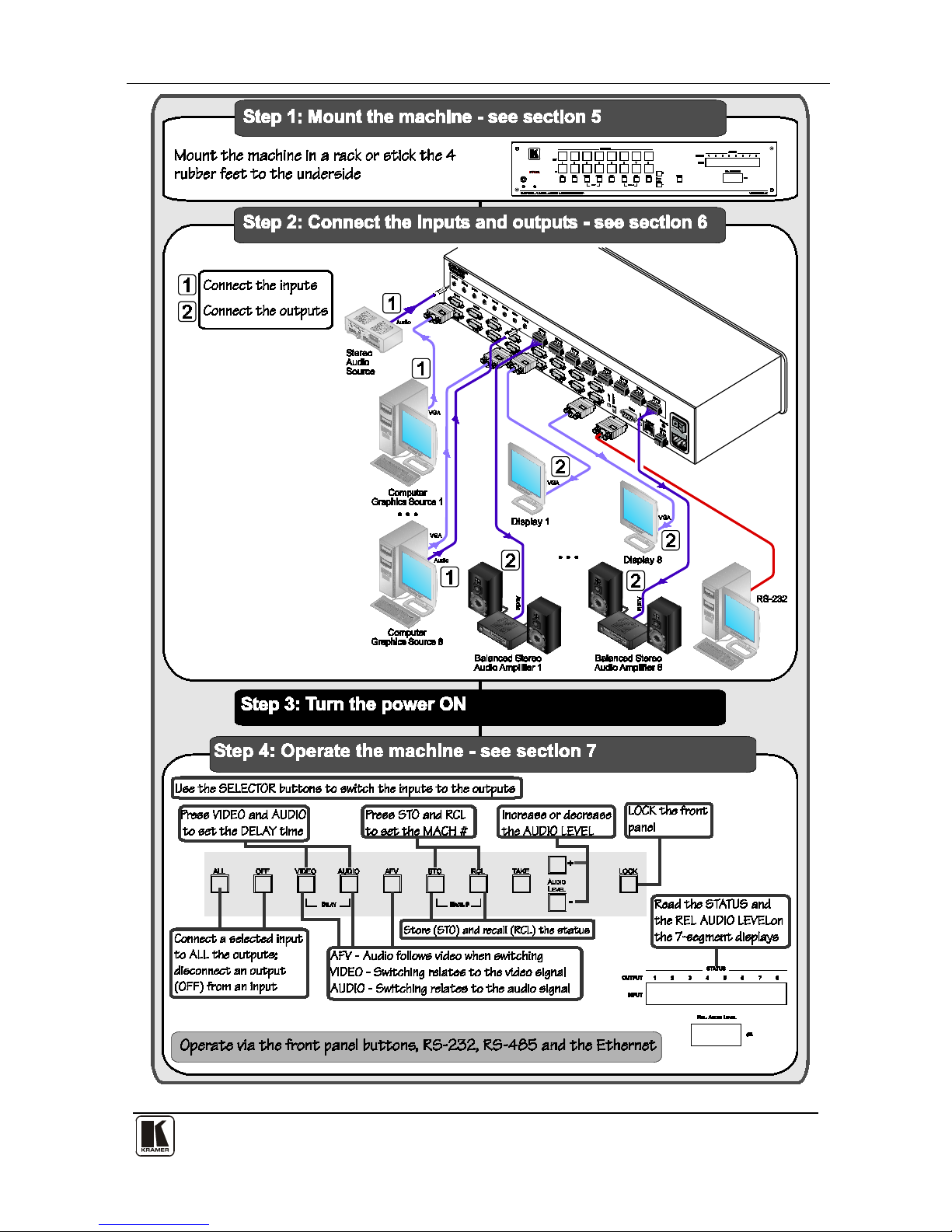
2.2 Quick Start
This quick start chart summarizes the basic setup and operation steps.
Getting Started
3
3

KRAMER: SIMPLE CREATIVE TECHNOLOGY
Overview
4
3 Overview
The VP-8x8AK is a high performance 8x8 computer graphics video matrix
switcher for high-resolution video and stereo audio signals. The VP-8x8AK
is HDTV compatible and let s you route any combination of inputs and
outputs.
In particular, the VP-8x8AK 8x8 VGA / UXGA / Audio Matrix Switcher
features:
• Kramer’s innovative integra ted sync processing; Kr-isp® technol ogy that
lets you achieve a sharp, stable image when the sync level is too low, by
restori ng the sync signal waveform
• A video bandwidth of over 360MHz that ensures transparent performance
even in the most critical applications
• 16 preset memory locations for quick access to common video and audio
configurations and audio gain status for each output
• Automatic detection of the co nnected i nput signa ls (the respective button
illuminates)
• A delayed switching mode (ranging from 0 to 3.5sec
1
) for clean
transitions whe n switchi ng between non-ge nlocked sources
• DC-coupled video inputs and outputs
• Audio-follow-video and breakaway options
• Eight stereo unbalanced stereo audio input signals on 3.5mm mini plugs
• Eight balanced stereo audio output signals on 5-pin terminal block
connectors
• Audio level control butto ns for adjusting t he signal l evel of each input
and each output
• Measurement and indication of the audio level for each input and output,
in relative dB
• A TAKE button, which allows you to place multiple s witc hes in a queue
and then a ctivate t hem simul t aneous ly with one touch of this b ut ton
• A LOCK button to prevent ta mpering with the front panel
• Supports DDC (Display Data Channel) communication between selected
input 1 and output 1 high-density 15-pin H D conn ectors on pin s 12 an d 15
• Control via embedded Web pages
1 In increments of 0.5sec

Your VP-8x8AK 8x8 VGA / UXGA / Audio Matrix Switcher
5
5
Control the VP-8x8AK using the front p anel buttons, or r emotely via:
• RS-485 or RS-232 serial commands (using Kramer 2000 and 3000
protocols) trans mitted by a touch screen system, PC, or other serial
controller
• The Kramer infrared remote control transmitter or infrared remote
extension cable transmitter (optional)
• Ethernet over a LAN
The VP-8x8AK is dependable, rugged, and fits into two vertical spaces (2U)
of a standard 19” professional rack.
To achieve the best performance:
• Use only good quality connection cables
1
to avoid interference,
deterioration in signal q uality due to poor matching, and elevated noise
levels (often associated with low quality cables)
• Do not secure the cables in tight bundles or roll the slack int o tight coils
• Avoid interference from neighboring electrical appliances that may
adversely influence signal quality and positio n your Kramer VP-8x8AK
away from moisture, excessive sunlight and dust
4 Your VP-8x8AK 8x8 VGA / UXGA / Audio Matrix Switcher
Figure 1, Figure 2, Table 1, and Table 2 define the VP-8x8AK 8x8 VGA /
UXGA / Audio Matrix Switcher.
1 Available from Kramer Electronics on our Web site at http://www.kramerelectronics.com
KRAMER: SIMPLE CREATIVE TECHNOLOGY
Your VP-8x8AK 8x8 VGA / UXGA / Audio Matrix Switcher
6
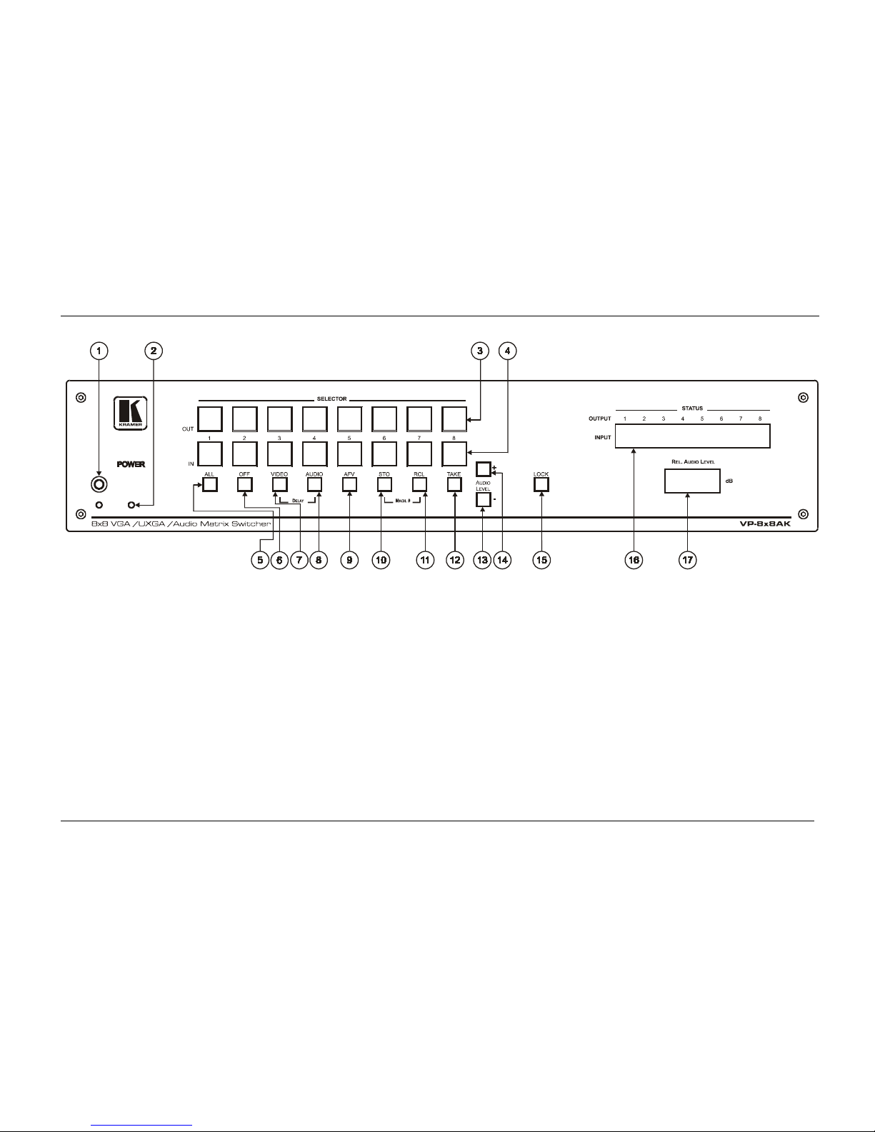
Figure 1: VP-8x8AK 8x8 VGA / UXGA / Audio Matrix Switcher – Fr ont View
Your VP-8x8AK 8x8 VGA / UXGA / Audio Matrix Switcher
7
7
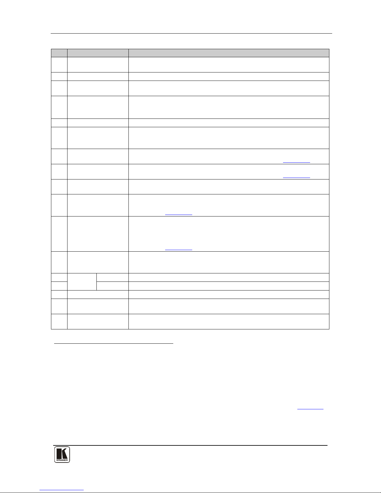
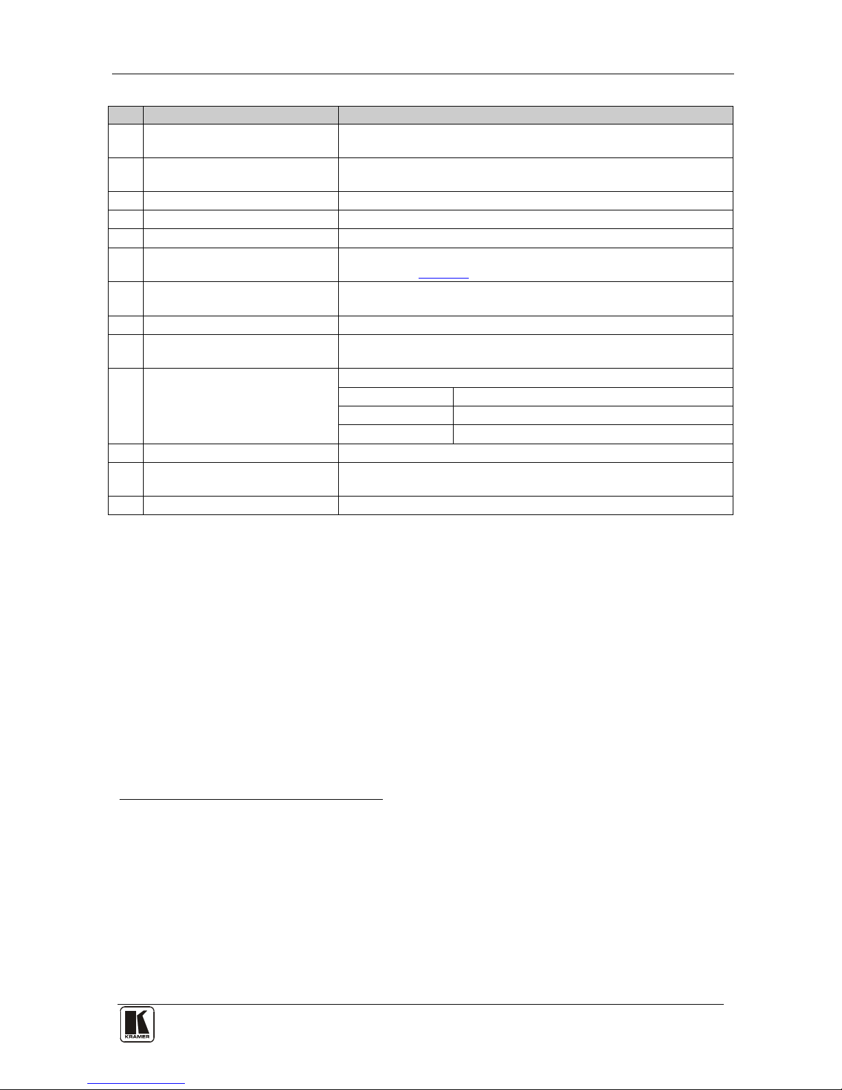
Table 1: Front Panel VP-8x8AK 8x8 VGA / UXGA / Audio Matrix Switcher Features
#
Feature
Function
1 IR Receiver The yellow LED is illuminated when receiving signals from the infrared
remote control transmitter
2 POWER LED The green LED is illuminated when the unit is turned ON
3 SELECTOR OUT
Buttons
Select the output1 to which the input is switched
4 SELECTOR IN
Buttons
Select the input1 to switch to the output (after selecting an output).
When a signal is detected at an input connector, the corresponding input
button is illuminated
5 ALL Button Pressing ALL followed by an INPUT button, connects that inp ut to a ll ou tpu ts2
6 OFF Button Press an OUT SELECTOR button and then an OFF button to disconnect that
output from the inputs.
Press the ALL button and then the OFF button to disconnect all the outputs
7 VIDEO Button When pressed3 actions relate to vide o. P ress the VIDEO button together
with the AUDIO button to set the Switching delay time (see
Section 6.7)
8 AUDIO Button When pressed4 actions relate to au dio. P ress the VIDEO button together
with the AUDIO button to set the Switching delay time (see Section
6.7)
9 AFV Button When pressed, the audio channels follow the video channels. The button is
illuminated when the AFV mode is selected
10 STO (Store) Button Pressing STO followed by an input/output button stores the current setting5.
Press the RCL button together with the STO button to set the machine
number (see
Section 6.8)
11 RCL (Recall) Button Pre ss ing th e RCL bu tt on and the co rre spondin g I N/OUT butto n r eca lls a set up
from the non-volatile memory.
Press the RCL bu tto n ag ain to imple ment t he new s tatus .
Press the RCL button together with the STO button to set the machine
number (see Section
6.8)
12 TAKE Button Pressing TA KE togg le s th e mod e be twee n th e Con fi r m mode6 and the At Once
mode (user confirmation per action is unnecessary). When in Confirm mode,
pressing the TAKE button will implement a pending configuration
13
AUDIO
LEVEL
- Button P ress to dec re ase t he input or output audio signal level
14 + Button Press to increase the input or output audio signal level
15 LOCK Button Disengages the front panel switches
16 STATUS 7-segment
display
Displays the selected INPUT switched to the OUTPUT (marked above each
input)
7
17 REL. AUDIO LEVEL
7-segment display
Displays8 the relative9 audio level10
1 From 1 to 8
2 For example, press ALL and then Input button # 2 to connect input # 2 to all the outputs
3 The VIDEO button is illuminated when in breakaway mode and actions relate to video
4 The AUDIO button is illuminated when in breakaway mode and actions relate to audio
5 For example, press STO and then the output button # 3 to store in Setup # 3, or the input button 4 to store in Setup 12
6 When in the Confirm mode, the TAKE button illuminates
7 Also displays the number of INPUT and OUTPUT ports, the firmware version number, and the MACHINE #. Refer to Section
7.2.1
8 A dot following the number, represents a value of 0.5. For example, 3.5 displays as "3."
9 The audio level range is relative, since the audio input signal can be adjusted separately via trimmers on the rear panel
10 The input audio level ranges from -100dB to +20dB and the output audio level ranges from -100dB to +7.5dB
KRAMER: SIMPLE CREATIVE TECHNOLOGY
Your VP-8x8AK 8x8 VGA / UXGA / Audio Matrix Switcher
8
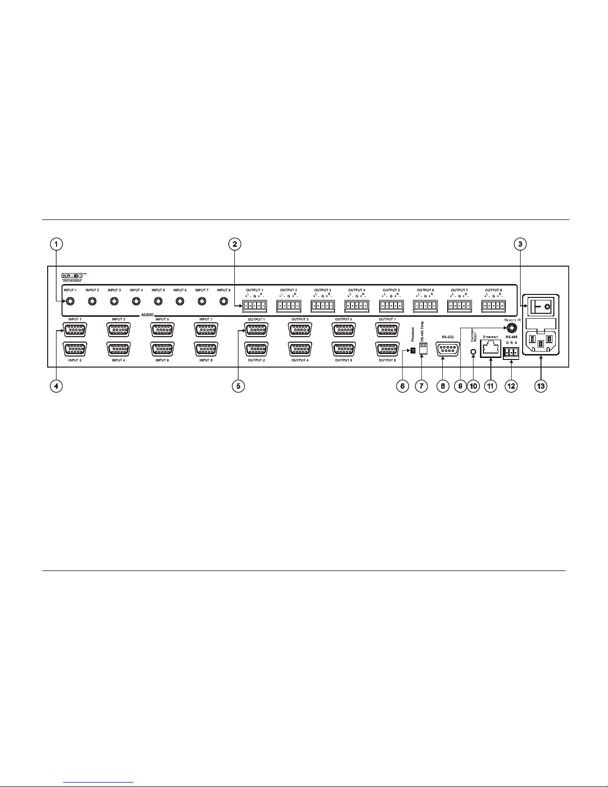
Figure 2: VP-8x8AK 8x8 VGA / UXGA / Audio Matrix Switcher – Rear View
Your VP-8x8AK 8x8 VGA / UXGA / Audio Matrix Switcher
9
Table 2: Rear Panel VP-8x8AK 8x8 VGA / UXGA / Audio Matrix Switcher Features
#
Feature
Function
1 AUDIO INPUT 3.5mm Mini
Connectors
Connect to the unbalanced stereo audio acceptors (from 1 to 8)
2 AUDIO OUTPUT Terminal Block
Connectors
Connect to bala nced s ter eo aud io sources (fro m 1 to 8)
3 Power Switch Illuminated switch for turning the unit ON or OFF
4 INPUT 15-pin HD Connectors C onn ect to t he video s ou rce s (from 1 to 8)
5 OUTPUT 15-pin HD Connectors Connect to the output ac ce pto rs (from 1 to 8)
6 PROG Button Push in for “Program” to upgrade to the latest Kramer firmware via
RS-232 (see Section
8), or release for “Normal” (the factory default)
7 RS-485 TERM DIP-switch Use for RS-485 Termination1: ON for RS-485 Line Termination with
120Ω; OFF for no RS-485 Line Termination
8 RS-232 9-pin D-sub Port Connects to the PC or the remote controller
9 REMOTE IR Opening2 Connects to an external IR rece iver unit for contr olling the machine via
an IR remote contro l ler in stead of us ing t he fr ont panel I R rece iver
3
10 FACTORY RESET Button Press to reset to fac tory defau l t def in ition s4:
IP Address: 192.168.1.39
Mask: 255.255.255.0
Gateway: 192.168.1.1
11 ETHERNET Connector Connect s to the PC or other serial controller through computer netw orking
12 RS-485 Terminal Block Port Pins B (-) and A (+) are for RS-485; Pin G (Ground) may be
connected to the shield of the cable if desired
13 Power Co nne ctor with Fuse AC connector enabling power supply to the unit
4.1 Usi n g th e IR Transmitter
You can use the RC-IR3 IR transmitte r t o cont rol th e m achine via the built-in IR
receiver on the front panel or, instead, via an optional external IR receiver
5
. The
externa l IR r eceiv er can b e l ocate d u p t o 15 meters away from the machine. This
distance can be extended to up to 60 meters when used with three extension cables
6
.
Before using the external IR receiver, be sure to arrange for your Kramer
dealer to insert the internal IR connection cable
7
with the 3.5mm connector
that fits into the REMOTE IR opening on the rear panel. Connect the exte rnal
IR receiver to the REMOTE IR 3.5mm connector.
1 The first and the last units on the RS-485 line should be terminated (ON). Other units should be unterminated (OFF)
2 Covered by a cap. The 3.5mm connector at the end of the internal IR connection cable fits through this opening
3 Optional. Can be used instead of the front panel (built-in) IR receiver to remotely control the machine (only if the in ternal
IR connection cable has been installed)
4 Turn the machine OFF usin g the power switch and then turn it ON while pressing the ETH Factory Reset button. The unit
will power up and load its memory with the factory default definitions
5 Model: C-A35M/IRR-50
6 Model: C-A35M/A35F-50
7 P/N: 505-70434010-S
KRAMER: SIMPLE CREATIVE TECHNOLOGY
Installing the VP-8x8AK in a Rack
10
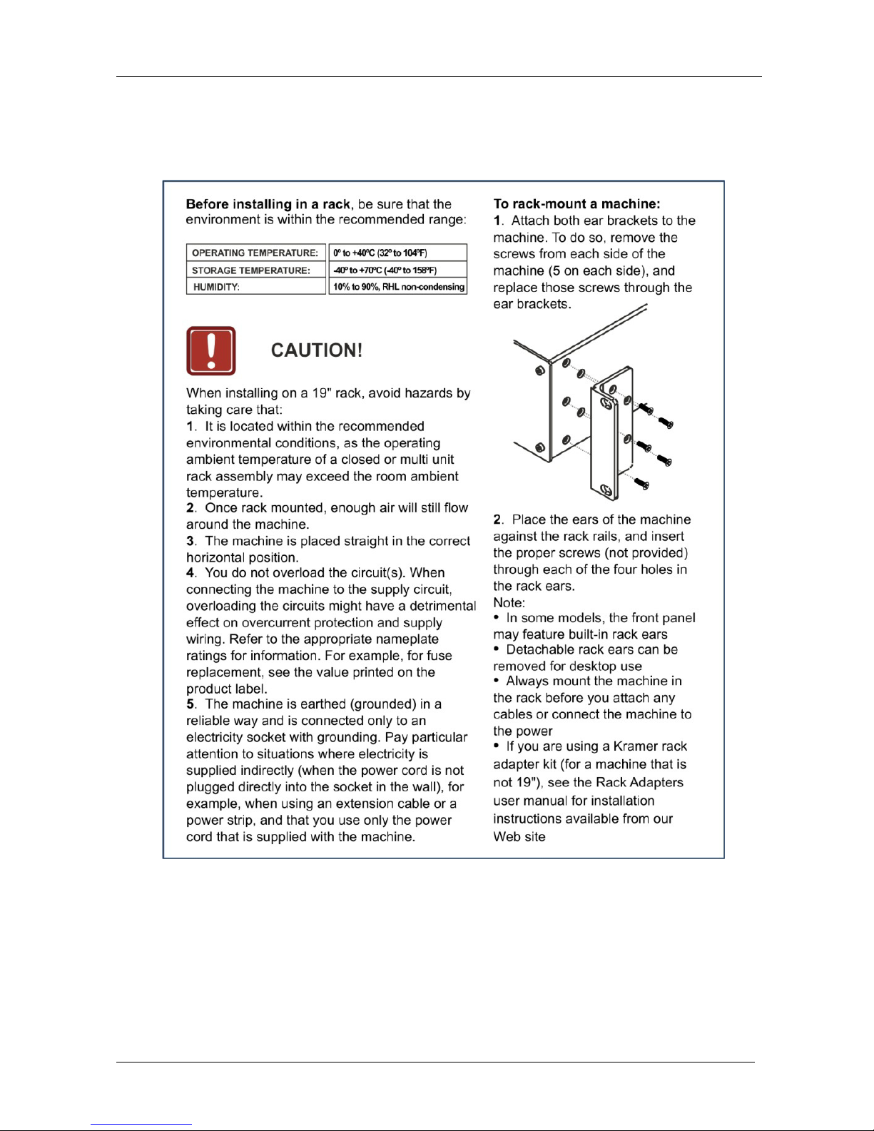
5 Installing the VP-8x8AK in a Rack
This section describes what to do before installing in a rack and how to rack
mount.

Using the VP-8x8AK
11
6 Using the VP-8x8AK
This section describes how to:
• Connect the VP-8x8AK rear panel (see Section
6.1)
• Connect a balanced stereo audio output (see Section
6.2)
• Connect the VP-8x8AK to a controlling device via RS-232 (see
Section
6.3), RS-485 (see Section 6.4) and/or the ETHERNET (see
Section
6.5)
• Set the switching delay time (see Section
6.7)
• Set the machine number (see Section
6.8)
• Connect several VP-8x8AK machines (see Section
6.9)
6.1 Connecting the VP-8x8AK Rear Panel
To connect
1
the VP-8x8AK, as illustrated in the exa mp le in Figure 3, do the
following
2
:
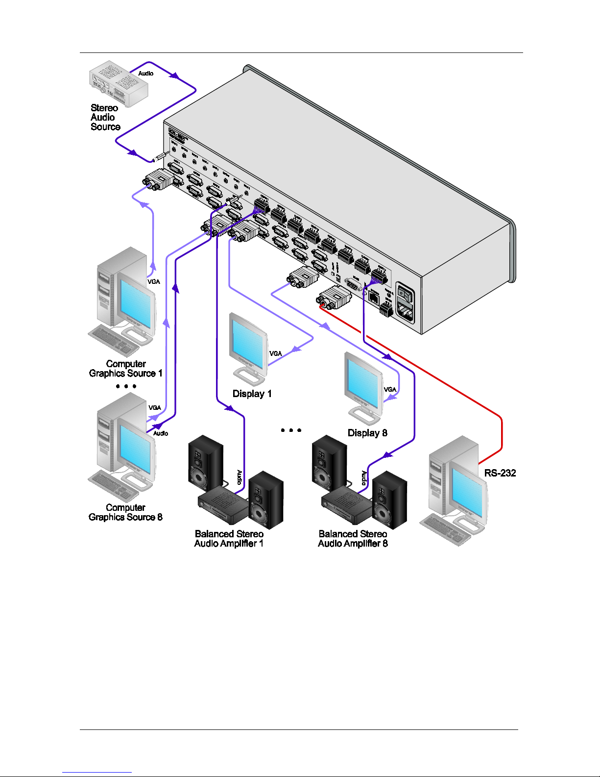
1. Connect up to eight VGA/UXGA computer graphics sources to the
INPUT 15-pin HD connectors.
2. Connect up to eight unbalanced stereo audio sources (for example, the
audio source of the computer, or a stereo audio source) to the eight
INPUT 3.5mm mini connectors.
3. Connect the eight OUTPUT 15-pin HD connectors to up to eight
VGA/UXGA video acceptors (for example, displays).
4. Connect the eight OUTPUT terminal block connectors to up to eight
balanced stereo audio acceptors (for example, balanced stereo audio
amplifiers with speakers).
5. If required, you can connect a PC and/or controller to the:
RS-232 port (See Section
6.3)
RS-485 port (see Section
6.4)
ETHERNET (see Section
6.5)
6. Connect the power cord (not s hown in
Figure 3)3.
1 You do not need to connect all inputs and outputs
2 Switch OFF the po wer on each device before connecting it to your VP-8x8AK. After connecting your VP-8x8AK, switch
on its power and then switch on the power on each device. DO NOT push in the rear panel Flash Program “PROG” button , it
is only used for upgrading to the latest Kramer firmware
3 We recommend that you use only the power cord that is supplied with this machine
KRAMER: SIMPLE CREATIVE TECHNOLOGY
Using the VP-8x8AK
12
Figure 3: Connecting the VP-8x8AK 8x8 VGA / UXGA / Audio Matrix Switcher
Using the VP-8x8AK
13
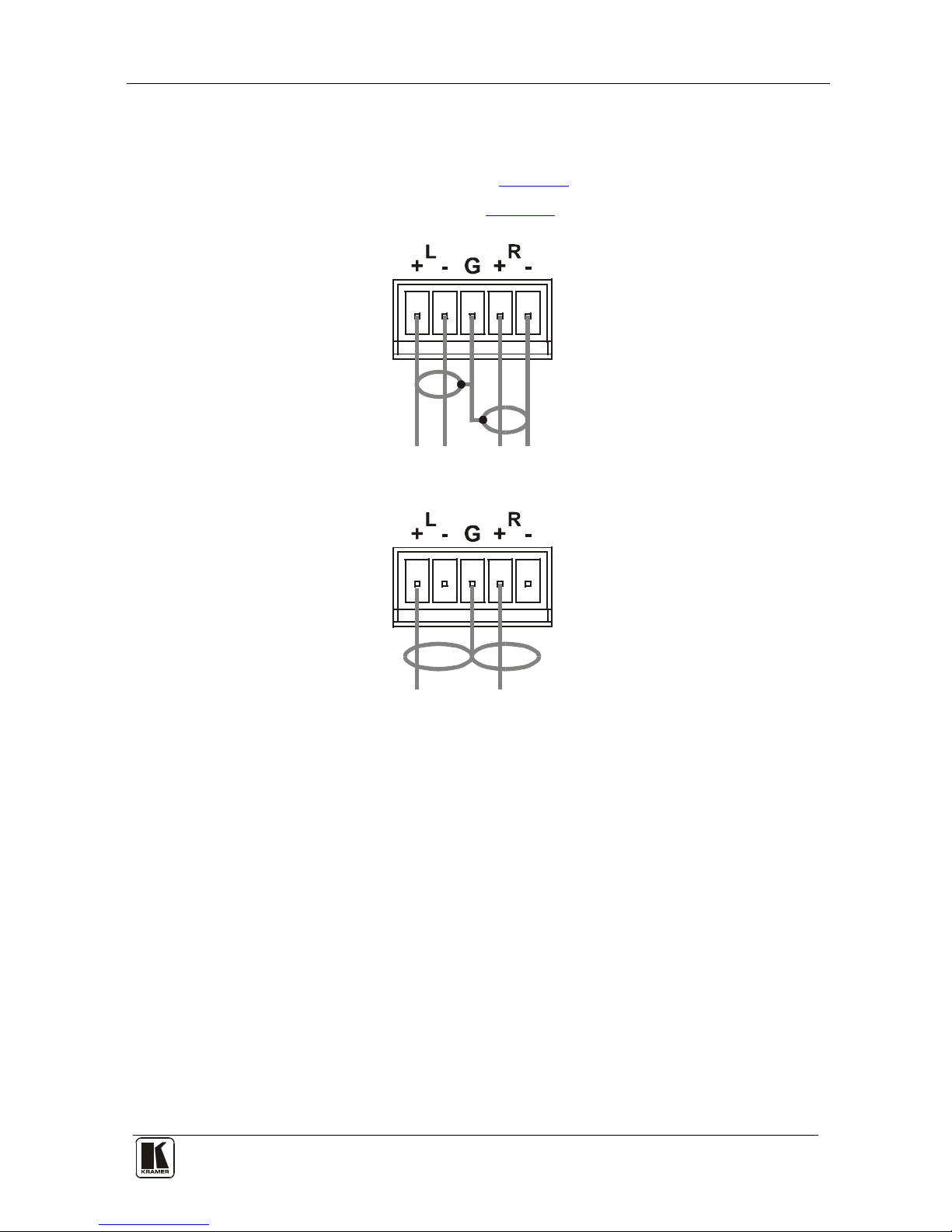
6.2 Connecting the Balanced/Unbalanced Stereo Audio Output
This section illustrates ho w to wire:
• A balanced output connection, see
Figure 4
• An unbalanced audio output, see
Figure 5
Figure 4: Connecting the Balanced Stereo Audio Output
Figure 5: Connecting an Unbalanced Output
6.3 Connecting a PC or Controller to the RS-232 Port
You can connect to the VP-8x8AK via an RS-232 connection using, for
example, a PC. Note that a null-modem adapter/connection is not required.
To connect to the VP-8x8AK via RS-232:
• Connect the RS-232 9-pin D-sub rear panel port on the product u nit via a
9-wire straight cable (only pin 2 to pin 2, pin 3 to pin 3, and pin 5 to pin 5
need to be connected) to the RS-232 9-pin D-sub port on your PC
6.4 Connecting a PC or Controller to the RS 485 Port
You can operate the VP-8x8AK via the RS-485 port from a distance of up to
1200m (3900ft) using any device equipped with an RS-485 port (for example,
a PC). For successful communication, you must set the RS-485 machine
number and bus termination.

KRAMER: SIMPLE CREATIVE TECHNOLOGY
Using the VP-8x8AK
14
To connect a device with a RS-485 port to the VP-8x8AK:
• Connect t he A (+) p i n on the RS-485 port of the PC to the A (+) pin on
the RS-485 port on the rear panel of the VP-8x8AK
• Connect the B (–) pin on the RS-485 port of the PC to the B (–) pin on the
RS-485 port on the rear panel of the VP-8x8AK
• Connect t he G pin o n the RS-485 port of the PC to the G pin on the
RS-485 port on the rear panel of the VP-8x8AK
6.5 Configuring the Ethernet Port
To configure the Ethernet port, you have to connect your PC t o the
VP-8x8AK either via the Ethernet (see Section
6.5.1) or via a serial port.
Once the machine is connected, you can configure the Ethernet port.
6.5.1 Connecting via the Ethernet
You can connect the VP-8x8AK via the ETHERNET in the following ways:
• For direct connection to the PC, use a crossover cable (see
Section
6.5.1.1)
• For connec tion via a network hub or network route r, use a
straight-through cable (see Section
6.5.1.2)
6.5.1.1 Connecting the ETHERNET Port Directly to a PC (Crossover Cable)
You can connect the Ethernet port of the machine to the Ethernet port on your
PC, via a crossover cable with RJ-45 connectors.
This type of connection is recommended for identification of the factory default
IP Address1 of the VP-8x8AK during the init ial config urat i on
After connecting the Ethernet port, configure your PC as follows:
1. Right-click the My Network Places icon on your desktop.
2. Select Properties.
3. Right-click Local Area Connection Properties.
4. Select Properties.
The Local Area Connection Properties window appears.
5. Select the Internet Protocol (TCP/IP) and click the Properties Button (see
Figure 6).
1 The default IP address is 192.168.1.39
 Loading...