


Kramer Electronics, Ltd.
USER MANUAL
Model:
VP-8x4AK
8x4 VGA / UXGA / Audio Matrix Swi t cher

Contents
i
Contents
1 Introduction 1
2 Getting Starte d 1
2.1 Quick Start 1
3 Overview 3
3.1 Terminology Used in this User Manual 4
3.2 DDC Support 5
3.3 Defining EDID 5
4 Your VP-8x4AK 8x4 VGA / UXGA / Audio Matrix Switcher 5
4.1 Using the IR Transmitter 9
5 Installing the VP-8x4AK in a Rack 10
6 Using the VP-8x4AK 11
6.1 Connecting the VP-8x4AK Rear Panel 11
6.2 Connecting the Balanced/Unbalanced S tereo Audio Output 13
6.3 Connecting a PC or Controller to the RS-232 Port 13
6.4 Connecting a PC or Controller to the RS 485 Port 14
6.4.1 Setting the VP-8x4AK 14
6.5 Configuring the Ethernet Port 15
6.5.1 Connecting via the Ethernet 15
6.5.2 Ethernet Port Configuration 17
6.6 Control via the Ethernet Port 18
6.7 Setting the Switching Delay Time 19
6.8 Setting the Machine Number 19
6.9 Cascading Machines 19
7 Operating the VP-8x4AK 21
7.1 Switching an Input to an Output 21
7.2 Understanding the 7-Segment Displays 21
7.2.1 The STATUS 7-Segment Display 21
7.2.2 The REL AUDIO LEVEL 7-Segment Display 22
7.3 Confirming Settings 22
7.3.1 Toggling between the At Once and Confirm Modes 22
7.3.2 Confirming a Switching Action 23
7.4 Storing/Recalling Input/Out p ut Con fi g ur a t ions 23
7.4.1 Storing an Input/Output Configuration 23
7.4.2 Recalling an Input/Output Configuration 24
7.5 Locking the Front Panel 24
7.6 Choosing the Audio-Follow-Video or Breakaway Option 24
7.6.1 Setting the Audio-Follow-Vi de o O pti o n 25
7.6.2 Setting the Breakaway Option 25

KRAMER: SIMPLE CREATIVE TECHNOLOGY
Contents
ii
7.7 The Audio Input/Output Gain Control 25
8 Flash Memory Upgrade 26
9 Controlling via the Embedded Web Pages 26
9.1 Connecting to the VP-8x4AK via your Browser 27
9.2 The VP-8x4AK Switching Matrix Page 28
9.2.1 Switch an Input to an Output via the Embedded Web Pages 29
9.2.2 Operate in the Confirm Mode 30
9.2.3 Store and Recall Setups 31
9.3 Audio Gain Page 33
9.4 The Configurations Page 34
10 Technical Specifications 35
11 Communication Parameters 36
12 Table of ASCII Codes for Serial Communication (Protocol 3000) 37
13 Hex Codes for Serial Communication (Pr ot ocol 2000) 38
14 Kramer Protocol 40
14.1 Switching Protocols 40
14.1.1 Switching Protocols via the Front Panel Buttons 40
14.1.2 Switching Protocols via Protoc ol Commands 40
14.2 Kramer Protocol 3000 40
14.2.1 Protocol 30 00 Syntax 41
14.2.2 Command Parts Details 42
14.3 Kramer Protocol 2000 48
Figures
Figure 1: VP-8x4AK 8x4 VGA / UXGA / Audio Matrix Switcher – Front View 6
Figure 2: VP-8x4AK 8x4 VGA / UXGA / Audio Matrix Switcher – Rear View 8
Figure 3: Connecting the VP-8x4AK 8x4 VGA / UXGA / Audio Matrix Switcher 12
Figure 4: Connect ing a Balanced Stereo Audio Output 13
Figure 5: Connecting an Unbalanced Stereo Audio Output 13
Figure 6: The RS-485 TERM DIP-switch 14
Figure 7: Local Area Connection Properties Window 16
Figure 8: Internet Protocol (TCP/IP) Properties Window 16
Figure 9: Connect Screen 17
Figure 10: Device Properties Screen 18
Figure 11: Control Configuration via RS-232 and RS-485 20
Figure 1 2: 7-segment Display during Normal Operation 21
Figure 13: REL AUDIO LEVEL 7-segment Display 22
Figure 14: Storing and Recalling using the Input/Output Buttons 23
Figure 15: Java Test Page Success Message 26
Figure 16: Entering the IP Number in the Address Bar 27
Figure 17: Loading the Embedded Web Pages 27
Figure 18: First Time Security Warning 28
Figure 19: VP-8x4AK Embedded Web Page 29

Contents
iii
Figure 20: Switching an Input to an Output 30
Figure 2 1: Switching an Input to an Output in the Confirm Mode 30
Figure 22: Exiting Offline Warning 31
Figure 23: Selecting a preset 31
Figure 24: Save Preset Message 32
Figure 25: Load Preset Message 32
Figure 26: Recalling a Preset in the Confirm Mode 33
Figure 27: Audio Gain 33
Figure 28: CONFIGURATIONS Embedded Web Page 34
Tables
Table 1: Terminology Used in this User Manual 4
Table 2: Front Panel VP-8x4AK 8x4 VGA / UXGA / Audio Matrix Switcher Features 7
Table 3: Rear P anel VP-8x4AK 8x4 VGA / UXGA / Audio Matrix Switcher Features 9
Table 4: Technical Specifications of the VP-8x4AK 8x4 Video Audio Matrix Switcher 35
Table 5: Communication Parameters 36
Table 6: VP-8x4AK Video Signal Codes for Protocol 3000 37
Table 7: VP-8x4AK Audio Signal Codes for Protocol 3000 37
Table 8: VP-8x4AK Audio Input Gain Codes 37
Table 9: VP-8x4AK Audio Output Gain Codes 38
Table 10: VP-8x4AK Hex Codes for Switching via RS-232/RS-485 38
Table 11: VP-8x4AK Hex Codes for Switching Audio Channels via RS-232/RS-485 38
Table 12: VP-8x4AK Hex Codes for Increasing/Decreasing the Audio Input Gain 39
Table 13: VP-8x4AK Hex Codes for Setting the Audio Input Gain 39
Table 14: VP-8x4AK Hex Codes for Increasing/Decreasing the Output Gain 39
Table 15: VP-8x4AK Hex Codes for Setting the Audio Output Gain 39
Table 16: Instruction Codes for Protocol 3000 43
Table 17: Protocol Definitions 48
Table 18: Instruction Codes for Protocol 2000 49

Introduction
1
1
1 Introduction
Welcome to Kramer Electronics! Since 1981, Kramer Electronics has been
providing a world of uni que, creat iv e, an d aff ordabl e s oluti ons to t h e vast range
of problems that confr ont th e video, audio, presentation, and broadcas ting
professional on a daily basis. In recent years, we have redesigned and upgraded
most of our line, making th e best ev en be tter! Our 1, 000-plus different models
now appear in 11 grou ps
1
Congratulations on purchasing your VP-8x4AK 8x4 VGA / UXGA / Audio
Matrix Switcher, which is ide al for the following typical applications:
that are clearly defined by function.
• Professional display systems requiring a true 8x4 computer graphics and
audio matrix operation
• Multimedia and presentation source, and acceptor selection
The package includes the following items:
• VP-8x4AK 8x4 VGA / UXGA Matrix Switcher
• Windows®-based Kramer control software
2
• Kramer RC-IR3 Infrared Remote Control Transmitter (including the
required battery and a separate user manual
4
)
• Power cord
3
, rack “ears” and this user manual
4
2 Getting Started
We recommend that you:
• Unpack the equipment carefully and save the original box and packa ging
materials for possible fut ure shipment
• Review the contents of this user manual
• Use Kramer high performance high-resolution cable s
5
2.1 Quick Start
This quick start chart summarizes the basic setup and operation steps.
1 GROUP 1: Distribution Amplifiers; GROUP 2: Switchers and Matrix Switchers; GROUP 3: Control Syste ms; GROUP 4:
Format/Standards Converters; GROUP 5: Range Extenders and Repeaters; GROUP 6: Specialty AV Products; GROUP 7:
Scan Converters and Scalers; GROUP 8: Cables and Connectors; G ROUP 9: Room Connectivity; GROUP 10: Accessories
and Rack Adapters; GROUP 11: Sierra Products
2 Downloadable from our Web site at
http://www.kramerelectronics.com
3 We recommend that you use only the power cord that is supplied with this machine
4 Download up-to-date Kramer user manuals from our Web site at http://www.kramerelectronics.com
5 The complete list of Kramer cables is on our Web site at http://www.kramerelectronics.com

KRAMER: SIMPLE CREATIVE TECHNOLOGY
Getting Started
2

Overview
3
3
3 Overview
The VP-8x4AK is a high performance 8x4 computer graphics video matrix
switcher for high-resolution video and stereo audio signals. The VP-8x4AK
is HDTV compatible and let s you route any combination of inputs and
outputs.
In particular, the VP-8x4AK 8x4 VGA / UXGA / A udio Matrix Switcher
features:
• Kramer’s innovative integra ted sync processing; Kr-isp® technol ogy that
lets you achieve a sharp, stable image when the sync level is too low, by
restori ng the sync signal waveform
• A video bandwidth of over 360MHz that ensures transparent performance
even in the most critical applications
• 16 preset memory locations for quick access to common video and audio
configurations and audio gain status for each output
• Automatic detection of the connected input signals (the respective button
illuminates)
• A delayed switching mode (ranging from 0 to 3.5sec
1
• DC-coupled video inputs and outputs
) for clean
transitions whe n switchi ng between non-ge nlocked sources
• Audio-follow-video and breakaway options
• Eight stereo unbalanced stereo audio input signals on 3.5mm mini plugs
• Four balanced stereo audio output signals on 5-pin terminal block
connectors
• Audio level control butto ns for adjusting t he signal l evel of each input
and each output
• Measurement and indication of the audio level for each input and output,
in relative dB
• A TAKE button, which allows you to place multiple s witc hes in a queue
and then a ctivate t hem simul t aneous ly with one touch of this b ut ton
• A LOCK button to prevent tampering with the front panel
• Support for DDC (Display Data Channel) communication between selected
input 1 and output 1 high-density 15-pin H D conn ectors on pin s 12 an d 15
• Control via embedded Web pages
1 In increments of 0.5sec

KRAMER: SIMPLE CREATIVE TECHNOLOGY
Overview
4
Control the VP-8x4AK using the front pa nel buttons, or remotel y via :
• RS-485 or RS-232 serial commands (using Kramer 2000 and 3000
protocols) trans mitted by a touch screen system, PC, or other serial
controller
• The Kramer infrared remote control transmitter or infrared remote
extension cable transmitter (optional)
• The ETHERNET
The VP-8x4AK is dependable, rugged, and fits into two vertical spaces (2U)
of a standard 19” professional rack.
To achieve the best performance:
• Use only good quality connection cables
1
• Avoid interference from neighboring electrical appliances that may
adversely influe nce signa l quality and position your Kramer VP-8x4AK
away from moisture, excessive sunlight and dust
to avoid interference,
deterioration in signal q uality due to poor matching, and elevated noise
levels (often associated with low quality cables).
3.1 Terminology Used in this User Manual
Table 1 defines some terms that are used in this user manual:
Table 1: Terminology Used in this User Manual
Term
Definition
802.3
The standard specification for ETHERNET that is maintained by the Institute of Electrical and
Electronics Engineers (IEEE).
Dynamic Host Configuration
Protocol (DHCP)
Allows the network administrator to distribute IP addresses from a central point and
automatically send a new IP address when an Ethernet point is plugged into a different
network location.
Gateway A network position serving as an entry to another network. On the Internet, a node or
stopping point can be either a gateway node or a host (end-point) node.
IP Address A 32-binary digit number that identifies each sender or receiver (within a network via a
particular server or workstation) of data (HTML pages or e-mails) that is sent in packets
across the Internet. Every device connected to an IP network must have a unique IP
address. This address is used to reference the specific unit.
Local Area Network (LAN) Computers sharing a common communications line or wireless link, which often share a
server within a defined geographic area.
Media Access Control
(MAC) Address
A computer's unique hardware number (or address) in a LAN or other network. On an
Ethernet LAN, the (MAC) address is identical to the Ethernet address.
Transmission Control
Protocol/Internet Protocol
(TCP/IP)
The basic communication language or protocol of the Internet that breaks the message into
appropriately sized packets for the network, and can be used as a communications protocol
in an intranet or an extranet.
1 Available from Kramer Electronics on our Web site at http://www.kramerelectronics.com

Your VP-8x4AK 8x4 VGA / UXGA / Audio Matrix Switcher
5
5
3.2 DDC Support
When establishing a VGA connection between a PC or laptop and a display
device, a set of parameters known as EDID is exchanged between them,
which is carried over the DDC channel. In some PC graphic cards and
laptops, this information exchange is essential for proper VGA OUT
operation.
3.3 Defining EDID
The Extended Display Identification Data (EDID
1
Note that EDID is s upported between the inp ut 1 and output 1 high-density
15-pin HD connectors on pins 12 and 15.
) is a data-structure,
provided by a displa y, to de scribe its capabilities to a grap hics card (that is
connected to the display’s source). The EDID enables the PC or laptop to
“know” what kind of monitor is connected to the output . The EDID includes
the manufacturer’s name, the product type, the timing data supported by the
display, the display size, luminance data and (for digital displays only) the
pixel mapping data.
4 Your VP-8x4AK 8x4 VGA / UXGA / Audio Matrix Switcher
Figure 1, Figure 2, Table 2, and Table 3 define the VP-8x4AK 8x4 VGA /
UXGA / Audio Matrix Switcher.
1 Defined by a standard published by the Video Electronics Standards Association (VESA)

KRAMER: SIMPLE CREATIVE TECHNOLOGY
Your VP-8x4AK 8x4 VGA / UXGA / Audio Matrix Switcher
6
Figure 1: VP-8x4AK 8x4 VGA / UXGA / Audio Matrix Switcher – Front View
Your VP-8x4AK 8x4 VGA / UXGA / Audio Matrix Switcher
7
7
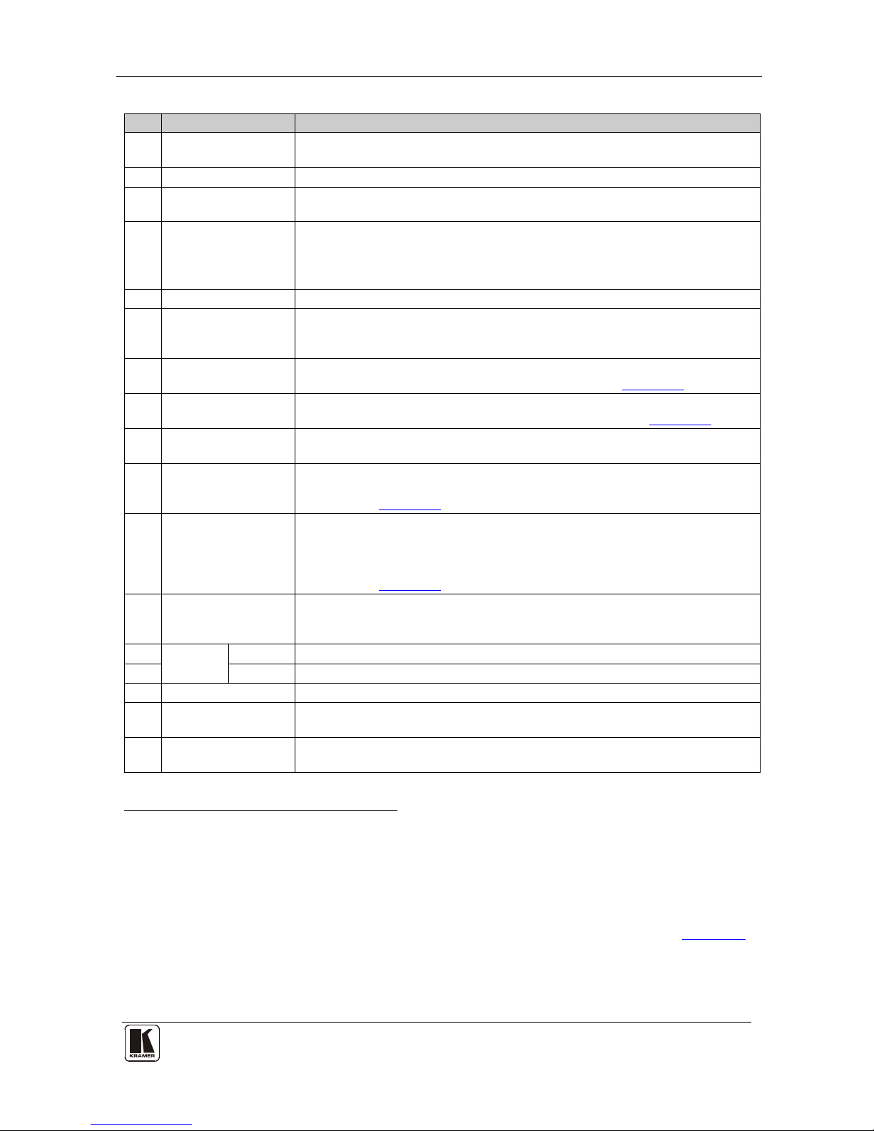
Table 2: Front Panel VP-8x4AK 8x4 VGA / UXGA / Audio Matrix Switcher Features
#
Feature
Function
1 IR Receiver The yellow LED is illuminated when receiving signals from the infrared
remote control transmitter
2 POWER LED The green LED is illuminated when the unit is turned ON
3 SELECTOR OUT
Buttons
Select the output (from 1 to 4) to which the inp ut is s witch ed
4 SELECTOR IN
Buttons
Select the input (from 1 to 8) to switch to the output (after selecting an
output).
When a signal is detected at an input connector, the corresponding input
button is illuminated
5 ALL Button Pressing ALL followed by an I N PU T button , conn ects tha t inp ut to a ll outpu ts
1
6 OFF Button Press an OUT SELECTOR button and then an OFF button to disconnect that
output from the inputs.
Press the ALL button and then the OFF button to disconnect all the outputs
7 VIDEO Button When pressed
2
6.7
actions relate to video. Press the VIDEO Button together with
the AUDIO button to set the Switching delay time (see Section )
8 AUDIO Button When pressed
3
6.7
actions relate to audio. Press the VIDEO Button together
with the AUDIO button to set the Switching delay time (see Section )
9 AFV Button When pressed, the audio channels follow the video channels. The button is
illuminated when the AFV mode is selected
10 STO (Store) Button Pressing STO followed by an input/output button stores the current setting
4
6.8
.
Press the RCL Button together with the STO button to set the machine
number (see Section )
11 RCL (Recall) Button Pressing the RCL bu tton a nd the co rre spondin g IN /OUT bu tto n r ecal ls a setup
from the non-volatile memory.
Press the RCL bu tto n ag ain to imple ment t he new s tatus .
Press the RCL Button together with the STO button to set the machine
number (see Section
6.8)
12 TAKE Button Pressing TA KE togg le s th e mod e be twee n th e Con fi r m mode
5
13
and the
At Once mode (user confirmation per action is unnecessary). When in Confirm
mode, pressing the TAKE button will implement a pending configuration
AUDIO
LEVEL
- Button Press to decrease the input or output audio signal level
14 + Button Press to increase the input or output audio signal level
15 LOCK Button Disengages the front panel switches
16 STATUS 7-segment
display
Displays the selected INPUT switched to the OUTPUT (marked above each
input)
6
17 REL. AUDIO LEVEL
7-segment display
Displays7 the relative8 audio level
9
1 For example, press ALL and then Input button # 2 to connect input # 2 to all the outputs
2 The VIDEO button is illuminated when in breakaway mode and actions relate to video
3 The AUDIO button is illuminated when in breakaway mode and actions relate to audio
4 For example, press STO and then the output button # 3 to store in Setup # 3, or the input button 4 to store in Setup 12
5 When in the Confirm mode, the TAKE button illuminates
6 Also displays the number of INPUT and OUTPUT ports, the firmware version number, and the MACHINE #. Refer to Section
7.2.1
7 A dot following the number represents a value of 0.5. For example, 3.5 displays as "3."
8 The audio level range is relative, since the audio input signal can be adjusted separately via trimmers on the rear panel
9 The input audio level ranges from -100dB to +20dB and the output audio level ranges from -100dB to +7.5dB
KRAMER: SIMPLE CREATIVE TECHNOLOGY
Your VP-8x4AK 8x4 VGA / UXGA / Audio Matrix Switcher
8
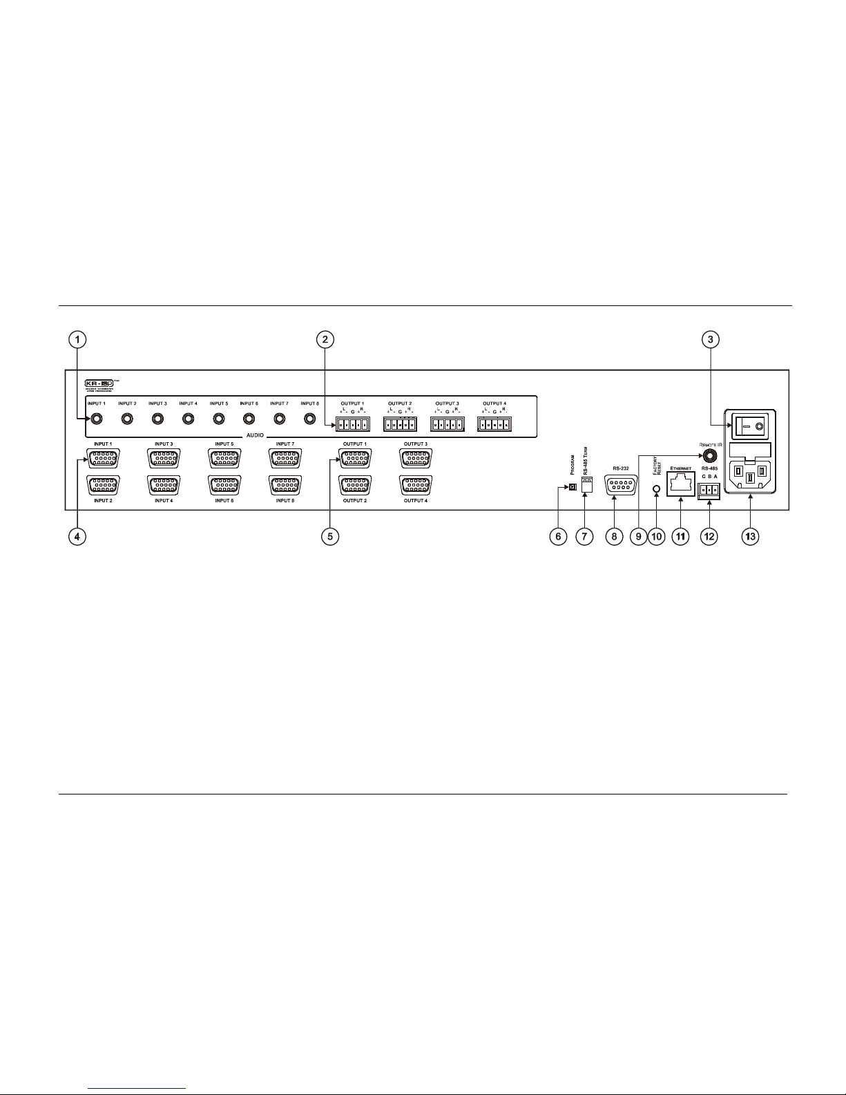
Figure 2: VP-8x4AK 8x4 VGA / UXGA / Audio Matrix Switcher – Rear View
Your VP-8x4AK 8x4 VGA / UXGA / Audio Matrix Switcher
9
9
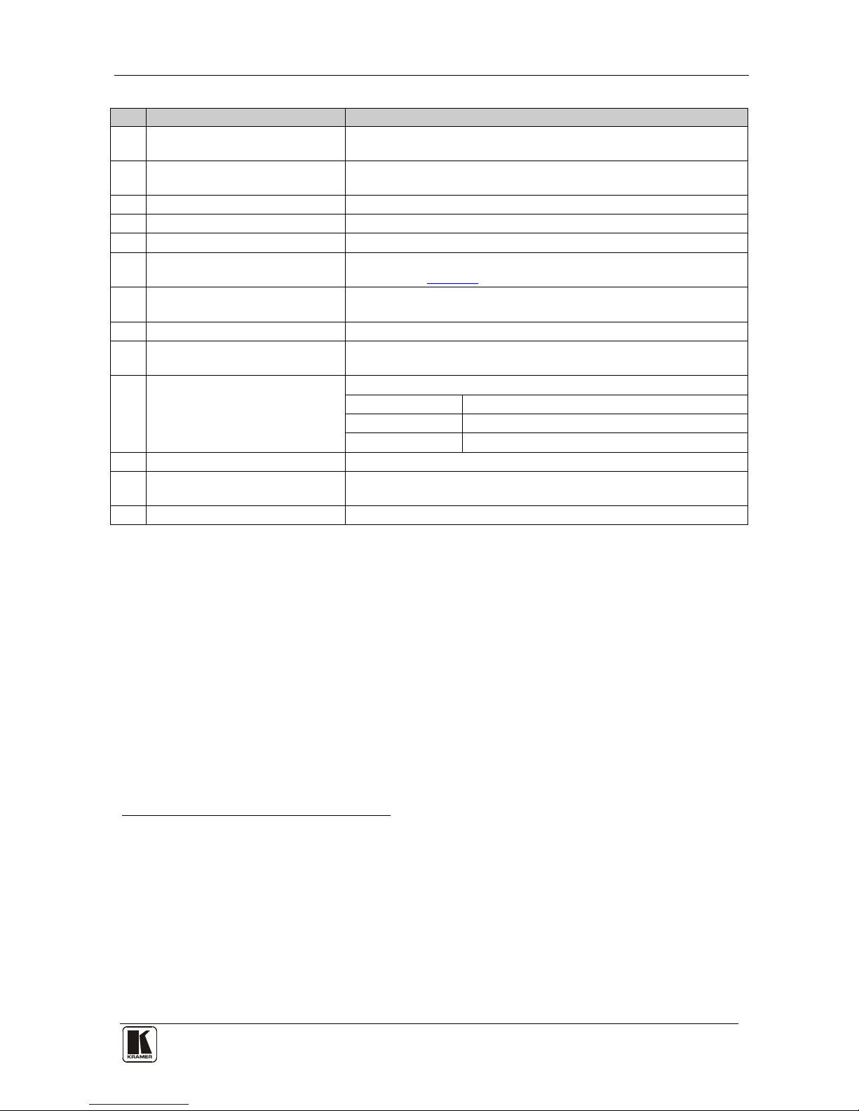
Table 3: Rear Panel VP-8x4AK 8x4 VGA / UXGA / Audio Matrix Switcher Features
#
Feature
Function
1 AUDIO INPUT 3.5mm Mini
Connectors
Connect to the unbalanced stereo audio acceptors (from 1 to 8)
2 AUDIO OUTPUT Terminal Block
Connectors
Connect to bala nced s ter eo aud io sources (from 1 to 4)
3 Power Switch Illuminated switch for turning the unit ON or OFF
4 INPUT 15-pin HD Connectors C onn ect to t he video s ou rce s (from 1 to 8)
5 OUTPUT 15-pin HD Connectors Connect to the output ac ce pto rs (from 1 to 4)
6 PROGRAM Button Push in for “Program” to upgrade to the latest Kramer firmware via
RS-232 (see Section
8), or release for “Normal” (the factory default)
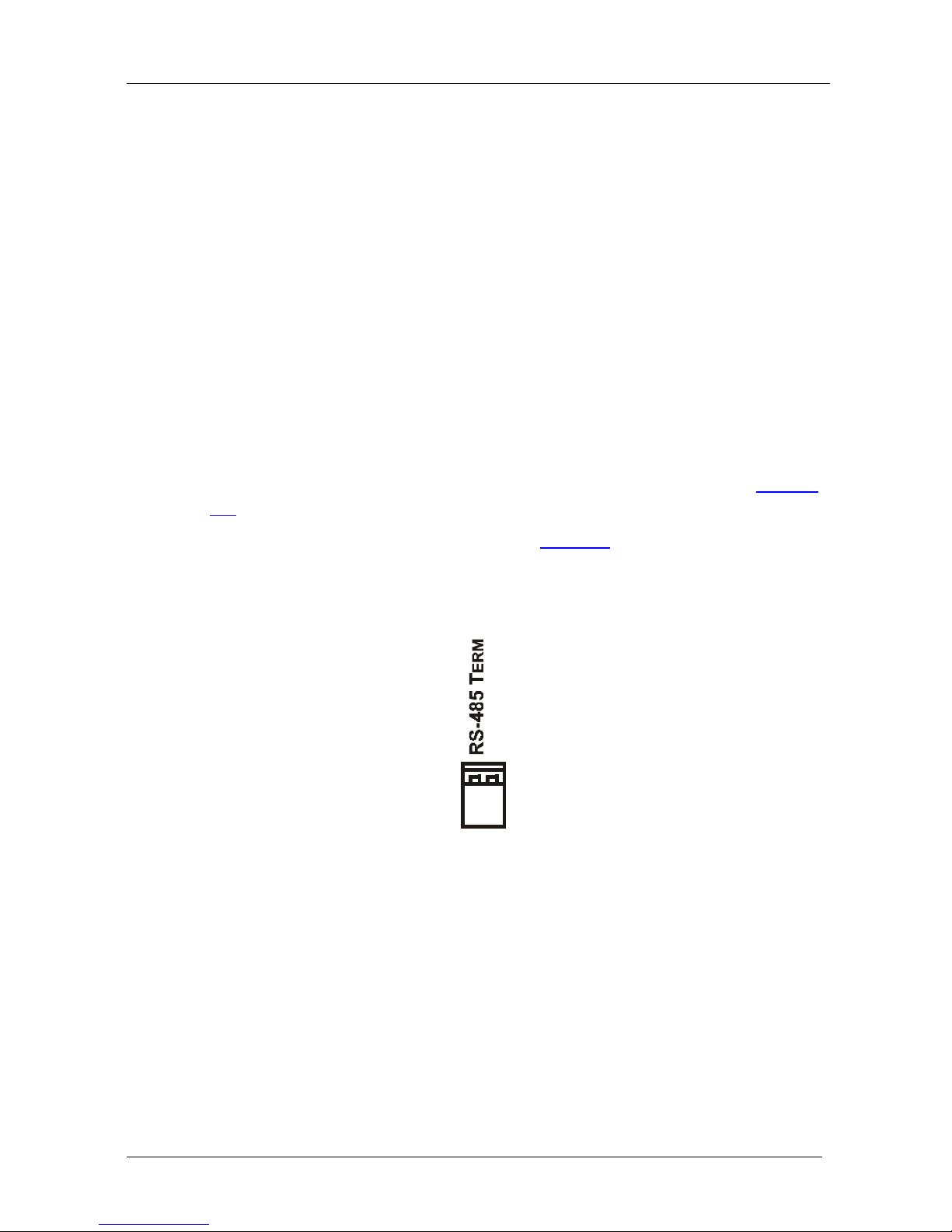
7 RS-485 TERM DIP-switch Use for RS-485 Termination
1
8
: ON for RS-485 Line Termination with
120Ω; OFF for no RS-485 Line Termination
RS-232 9-pin D-sub Port Connects to the PC or the remote controller
9 REMOTE IR Opening
2
Connects to an external IR rece iver unit for contr olling the machine via
an IR remote contro l ler in stead of us ing t he fr ont panel I R rece iver
3
10 FACTORY RESET Button Press to reset t o factory default definitions
4
:
IP Address: 192.168.1.39
Mask: 255.255.255.0
Gateway: 192.168.1.1
11 ETHERNET Connector Connects to the PC or other serial control ler through computer networ king
12 RS-485 Terminal Block Port Pins B (-) and A (+) are for RS-485; Pin G (Ground) may be
connected to the shield of the cable if desired
13 Power Co nne ctor with Fuse AC connector enabling power supply to the unit
4.1 Usi n g th e IR Transmitter
You can use the RC-IR3 IR transmitter to control the machine via the built-in
IR receiver on the front panel or, instead, via an optional external IR
receiver
5
. The external IR receiver can be located up to 15 meters away from
the machine. This distance can be extended to up to 60 meters when used
with three extension cables
6
Before us ing the ext ernal IR receiver, be sure to arrange for your Kramer
dealer to insert the internal IR connection cable
23F
7
with the 3.5mm conne ctor
that fits into the REMOTE IR opening on the rear panel. Connect the external
IR receiver to the REMOTE IR 3.5mm connector.
1 The first and the last units on the RS-485 line should be terminated (ON). Other units should be unterminated (OFF)
2 Covered by a cap. The 3.5mm connector at the end of the internal IR connection cable fits through this opening
3 Optional. Can be used instead of the front panel (built-in) IR receiver to remotely control the machine (only if the in ternal
IR connection cable has been installed)
4 Turn the machine OFF usin g the power switch and then turn it ON while pressin g the ETH Factory Reset button. The u nit
will power up and load its memory with the factory default definitions
5 Model: C-A35M/IRR-50
6 Model: C-A35M/A35F-50
7 P/N: 505-70434010-S

KRAMER: SIMPLE CREATIVE TECHNOLOGY
Installing the VP-8x4AK in a Rack
10
5 Installing the VP-8x4AK in a Rack
.
This sect ion provi des instructio ns for rack mounting the unit.

Using the VP-8x4AK
11
11
6 Using the VP-8x4AK
This section describes how to:
• Connect the VP-8x4AK rear panel (see Section
6.1)
• Connect a balanced stereo audio output (see Section
6.2)
• Connect the VP-8x4AK to a controlling device via RS-232 (see Section
6.3), RS-485 (see Section 6.4) and/or the ETHERNET (see Section 6.5)
• Set the switching delay time (see Section
6.7)
• Set the machine number (see Section
6.8)
• Connect several VP-8x4AK machines (see Section
6.9)
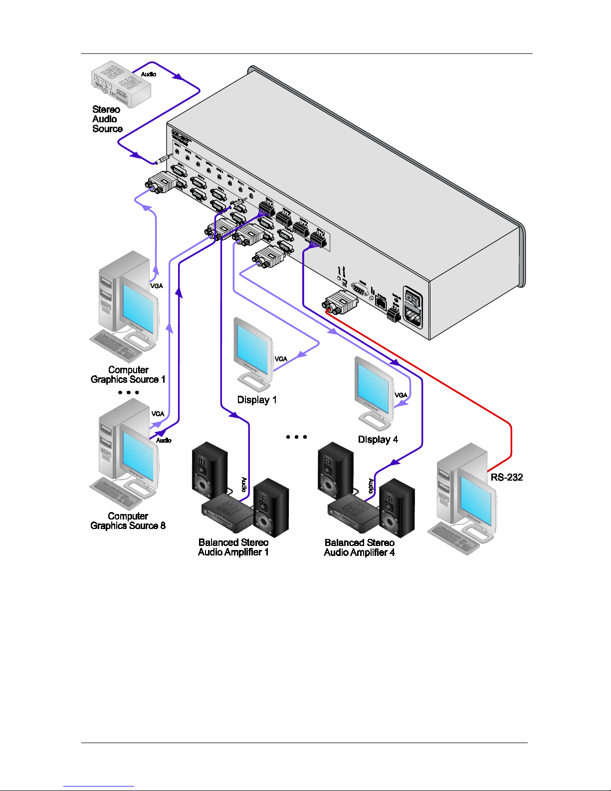
6.1 Connecting the VP-8x4AK Rear Panel
To connect
1
Figure 3 the VP-8x4AK, as illustrated in the example in , do the
following
2
1. Connect up to eight VGA/UXGA computer graphics sources to the
INPUT 15-pin HD connectors.
:
2. Connect up to eight unbalanced stereo audio sources (for example, the
audio source of the computer, or a stereo audio source) to the eight
INPUT 3.5mm mini connectors.
3. Connect the eight OUTPUT 15-pin HD connectors to up to eight
VGA/UXGA video acceptors (for example, displays).
4. Connect the eight OUTPUT terminal block connectors to up to eight
balanced stereo audio acceptors (for example, balanced stereo audio
amplifiers with speakers).
5. If required, you can connect a PC and/or controller to the:
RS-232 port (see Section
6.3)
RS-485 port (see Section
6.4)
ETHERNET (see Section
6.5)
6. Connect the power cord ( not shown i n
Figure 3)
3
.
1 You do not need to connect all inputs and outputs
2 Switch OFF the po wer on each device before connecting it to your VP-8x4AK. After connecting your VP-8x4AK, switch
on its power and then switch on the power on each de vice. DO NOT push in the rear panel Flash Program “PROGRAM”
button , it is only used for upgrading to the latest Kramer firmware
3 We recommend that you use only the power cord that is supplied with this machine
KRAMER: SIMPLE CREATIVE TECHNOLOGY
Using the VP-8x4AK
12
Figure 3: Connecting the VP-8x4AK 8x4 VGA / UXGA / Audio Matrix Switcher

Using the VP-8x4AK
13
13
6.2 Connecting the Balanced/ Unbal ance d Ster eo Audio Out put
This section illustrates ho w to wire:
• A balanced output connection, see
Figure 4
• An unbalanced audio output, see
Figure 5
Figure 4: Connecting a Balanced Stereo Audio Output
Figure 5: Connecting an Unbalanced Stereo Audio Output
6.3 Connecting a PC or Controller to the RS-232 Port
You can connect to the VP-8x4AK via an RS-232 connection using, for
example, a PC. Note that a null-modem adapter/connection is not required.
To connect to the VP-8x4AK vi a RS-232:
• Connect the RS-232 9-pin D-sub rear panel port on the product u nit via a
9-wire straight cable (only pin 2 to pin 2, pin 3 to pin 3, and pin 5 to pin 5
need to be connected) to the RS-232 9-pin D-sub port on your PC
KRAMER: SIMPLE CREATIVE TECHNOLOGY
Using the VP-8x4AK
14
6.4 Connecting a PC or Controller to the RS 485 Port
You can operate the VP-8x4AK via the RS-485 port from a distance of up to
1200m (3900ft) using any device equipped with an RS-485 port (for example,
a PC). For successful communication, you must set the RS-485 machine
number and bus termination.
To connect a device with a RS-485 port to the VP-8x4AK:
• Connect the A (+) pin on the RS-485 port of the PC to the A (+) pin on
the RS-485 port on the rear panel of the VP-8x4AK
• Connect the B (–) pin on the RS-485 port of the PC to the B (–) pin on the
RS-485 port on the rear panel of the VP-8x4AK
• Connect the G pin on the RS-485 port of the PC to the G pin on the
RS-485 port on the rear panel of the VP-8x4AK
6.4.1 Setting the VP-8x4AK
1. Set the VP-8x4AK unit to a Machine # other than 1, according to Section
6.8.
2. Set the RS-485 TERM DIP-switch (see
Figure 6 ) ON (for RS-485 Line
Termination with 120Ω) if it is the only machine being controlled via this
RS-485 line (if multiple machines are being controlle d, then only the last
one on the RS-485 line should be set to ON).
Figure 6: The RS-485 TERM DIP-switch
 Loading...