

Kramer VP-885 User Manual

Kramer Electronics, Ltd.
USER MANUAL
Model:
VP-885
8x8 Multiformat Video / Balanced Audio Matrix Switcher

Contents
i
Contents
1 Introduction 1
2 Getting Started 1
2.1 Quick Start 1
3 Overview 3
3.1 Terminology Used in this Manual 4
4 Defining the VP-885 5
4.1 Using the IR Transmitter 8
5 Installing the VP-885 in a Rack 9
6 Connecting the VP-885 10
6.1 Connecting a Balanced/Unbalanced Stereo Audio Input/Output 11
6.2 Connecting to the VP-885 via RS-232 12
6.3 Connecting to the VP-885 via RS-485 13
6.4 Connecting to the VP-885 via Ethernet 13
6.4.1 Connecting Directly via the Ethernet Port 14
6.4.2 Connecting via a Network Hub, Switch, or Router 16
6.4.3 Configuring the Ethernet Port on the VP-885 16
6.5 Setting the VP-885 DIP-switches 18
7 Operating the VP-885 19
7.1 Displaying the Configuration of the VP-885 19
7.2 Switching Outputs to Inputs 19
7.3 Confirming Settings 20
7.3.1 Toggling between At Once and Confirm Modes 20
7.3.2 Confirming a Switching Action 20
7.4 Defining the 7-Segment Status Display Information 21
7.4.1 Status Display Immediately After Power is Turned On 21
7.4.2 Status Display During Normal Operation 22
7.4.3 Status Display During Audio Gain Level Setting 22
7.5 Choosing the Audio-Follow-Video or Breakaway Option 23
7.5.1 Setting the Audio-Follow-Video Option 23
7.5.2 Setting the Breakaway Option 23
7.6 Storing/Recalling Input-Output Configurations 23
7.6.1 Storing an Input-Output Configuration 24
7.6.2 Recalling an Input-Output Configuration 24
7.6.3 Deleting an Input-Output Configuration 24
7.7 Audio Input/Output Gain Control 24
7.8 Resetting the Unit 26
8 Controlling the VP-885 26
8.1 Controlling the VP-885 via RS-232 26
8.2 Controlling the VP-885 via RS-485 28

KRAMER: SIMPLE CREATIVE TECHNOLOGY
Contents
ii
8.3 Controlling the VP-885 via Ethernet 28
9 Updating the Firmware 30
10 Connecting to the VP-885 via your Browser 30
10.1 The Main Switching Matrix Page 32
10.1.1 Switching an Input to an Output 32
10.1.2 Setting the AFV Mode 33
10.1.3 Operating in the Offline Mode 34
10.1.4 Storing and Recalling Setups 35
10.1.5 Locking the Front Panel Buttons 37
10.2 Audio Input Gain Control Page 38
10.3 The Configuration Page 38
11 Communication Parameters 40
12 Technical Specifications 41
13 Tables of ASCII Codes for Serial Communication (Protocol 3000) 42
14 Tables of Hex Codes for Serial Communication (Protocol 2000) 43
15 Kramer Protocol 45
15.1 Switching Protocols 45
15.1.1 Switching Protocols via the Front Panel Buttons 45
15.1.2 Switching Protocols via Protocol Commands 45
15.2 Kramer Protocol 3000 45
15.2.1 Protocol 3000 Syntax 46
15.2.2 Command Parts Details 46
15.3 Kramer Protocol 2000 53
Figures
Figure 1: VP-885 8x8 Multiformat Video/Balanced Audio Matrix Switcher Front Panel 5
Figure 2: VP-885 8x8 Multiformat Video/Balanced Audio Matrix Switcher Rear Panel
7
Figure 3: Connecting the VP-885
10
Figure 4: Wiring a Balanced Stereo Audio Input/Output 11
Figure 5: Wiring an Unbalanced Stereo Audio Output
12
Figure 6: Wiring an Unbalanced Source to a Balanced Input
12
Figure 7: Connecting to the VP-885 via RS-232 using a PC
12
Figure 8: Connecting to the VP-885 via Ethernet 14
Figure 9: Local Area Connection Properties Window
15
Figure 10: Internet Protocol (TCP/IP) Properties Window
15
Figure 11: Connect Window
16
Figure 12: Device Properties Window 17
Figure 13: VP-885 DIP-switches
18
Figure 14: Status Display Immediately After Turn On
21
Figure 15: Status Display 5 Seconds After Turn On 22
Figure 16: Status Display During Normal Operation 22
Figure 17: Status Display Showing OUTPUT 3, Gain -4.5
22
Figure 18: Configuration Button Numbering
24

Contents
iii
Figure 19: Status Display OUTPUT 8 Flashing 25
Figure 20: Status Display Showing OUTPUT 8, Gain -4.5
25
Figure 21: Control Configuration via RS-232
27
Figure 22: Controlling the VP-885 via Ethernet 29
Figure 23: Entering the IP Number in the Address Bar
30
Figure 24: The Loading Page
30
Figure 25: First Time Security Warning
31
Figure 26: Main Switching Matrix Page 32
Figure 27: Selecting a Switching Point on the Matrix
33
Figure 28: Switching an Input to an Output
33
Figure 29: AFV Mode Warning
34
Figure 30: AFV Mode Audio Channels Switched 34
Figure 31: Switching Audio in the Offline Mode
35
Figure 32: Exiting Offline Warning
35
Figure 33: Selecting Preset 07
36
Figure 34: Selecting Preset 03 37
Figure 35: Recalling a Preset in Offline Mode
37
Figure 36: Audio Gain Control Page
38
Figure 37: Selecting Audio Input Gain for Channel 2
38
Figure 38: Configuration Page 39
Tables
Table 1: Terminology Used in this User Manual 4
Table 2: VP-885 Front Panel Features
6
Table 3: VP-885 Rear Panel Features
8
Table 4: DIP-switch Settings 18
Table 5: Machine Number DIP-switch Settings
18
Table 6: Communication Parameters
40
Table 7: Technical Specifications for the VP-885
41
Table 8: VP-885 Video Signal Codes
42
Table 9: VP-885 Audio Signal Codes 42
Table 10: VP-885 Audio Input Gain Codes
42
Table 11: VP-885 Audio Output Gain Codes
43
Table 12: VP-885 Hex Codes that Switch Video Channels
43
Table 13: VP-885 Hex Codes that Switch Audio Channels 43
Table 14: VP-885 Hex Codes that Increase/Decrease Audio Input Gain
44
Table 15: VP-885 Hex Codes that Set the Audio Input Gain
44
Table 16: VP-885 Hex Codes that Increase/Decrease the Audio Output Gain 44
Table 17: VP-885 Hex Codes that Set the Audio Output Gain 44
Table 18: Instruction Codes for Protocol 3000
47
Table 19: Protocol Definitions
53
Table 20: Instruction Codes for Protocol 2000
54

Introduction
1
1 Introduction
Welcome to Kramer Electronics! Since 1981, Kramer Electronics has been providing a world
of unique, creative, and affordable solutions to the vast range of problems that confront the
video, audio, presentation, and broadcasting professional on a daily basis. In recent years, we
have redesigned and upgraded most of our line, making the best even better! Our 1,000-plus
different models now appear in 11 groups
1
Congratulations on purchasing your VP-885 8x8 Multiformat Video/Balanced Audio
Matrix Switcher which is ideal for the following typical applications:
that are clearly defined by function.
• Professional display systems requiring a true 8x8 computer graphics and audio
matrix operation
• Multimedia and presentation source, and acceptor selection
The package includes the following items:
• VP-885 8x8 Multiformat Video/Balanced Audio Matrix Switcher
• Windows®-based Kramer Control software
2
• Kramer RC-IR3 Infrared Remote Control Transmitter (including the required
battery and a separate user manual
4
)
• Power cord
3
and this user manual
4
2 Getting Started
We recommend that you:
• Unpack the equipment carefully and save the original box and packaging
materials for possible future shipment
• Review the contents of this user manual
• Use Kramer high performance high-resolution cables
5
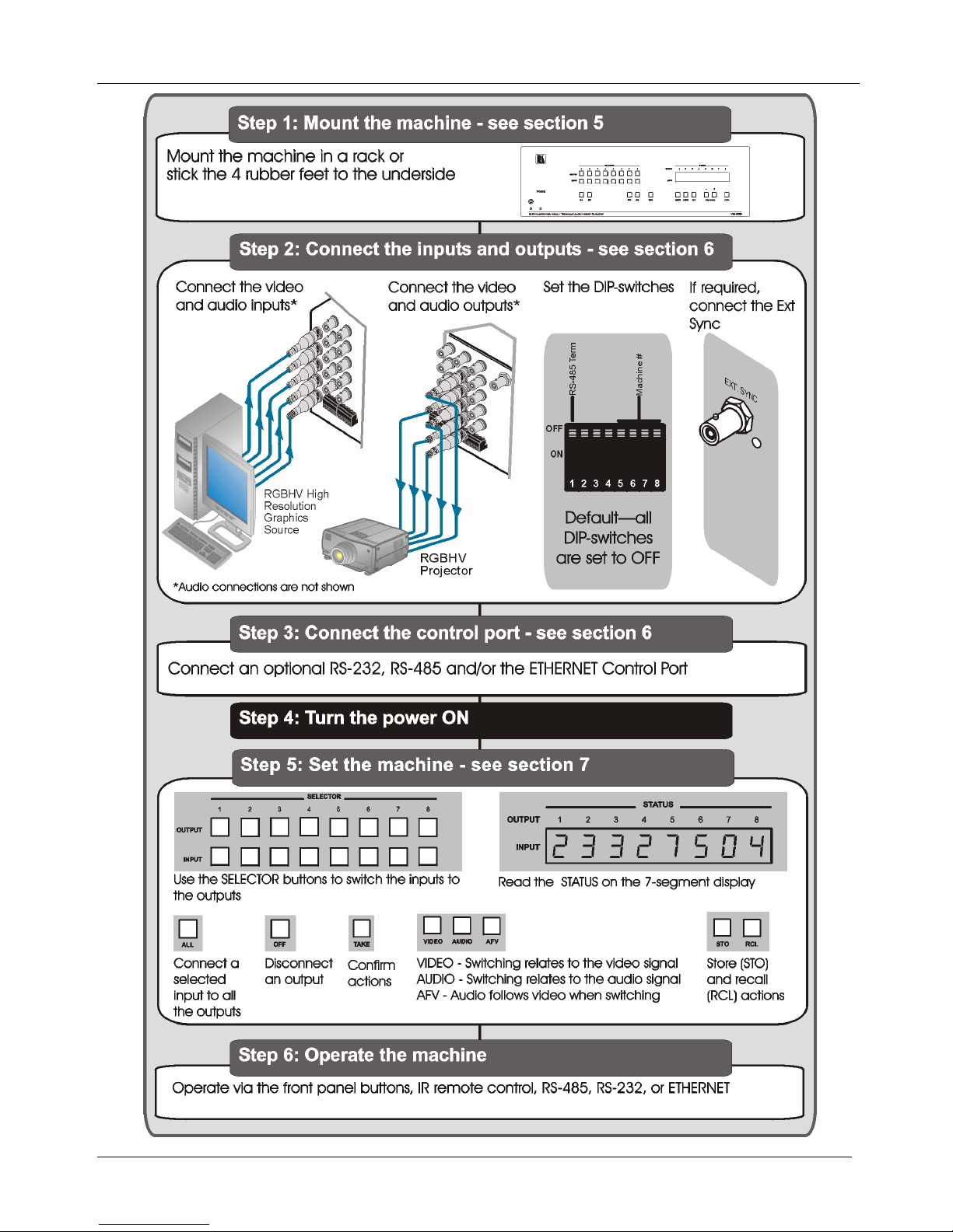
2.1 Quick Start
The following quick start chart summarizes the basic steps when connecting a VP-885.
1 GROUP 1: Distribution Amplifiers; GROUP 2: Switchers and Matrix Switchers; GROUP 3: Control Systems; GROUP 4:
Format/Standards Converters; GROUP 5: Range Extenders and Repeaters; GROUP 6: Specialty AV Products; GROUP 7: Scan
Converters and Scalers; GROUP 8: Cables and Connectors; GROUP 9: Room Connectivity; GROUP 10: Accessories and Rack
Adapters; GROUP 11: Sierra Products
2 Download from our Web site at
http://www.kramerelectronics.com
3 We recommend that you use only the power cord that is supplied with this machine
4 Download up-to-date Kramer user manuals from our Web site at
http://www.kramerelectronics.com
5 The complete list of Kramer cables is on our Web site at
http://www.kramerelectronics.com
KRAMER: SIMPLE CREATIVE TECHNOLOGY
Getting Started
2

Overview
3
3 Overview
The high performance VP-885 is a multiformat matrix switcher for composite video,
s-Video, component video (Y, Cb/Pb, and Cr/Pr), balanced stereo audio, and S/PDIF
digital audio signals. It can route any or all inputs to any or all outputs
simultaneously. The VP-885 8x8 Multiformat Video/Balanced Audio Matrix
Switcher features:
• High Bandwidth (350MHz @-3dB) fully loaded
• HDTV compatibility
• A TAKE button to execute multiple switches all at once
• Memory locations that can be used to store multiple switches as presets to be
recalled and executed when needed
• Audio (analog) breakaway switching, for switching audio independently from
video
The VP-885 is housed in a 19” 3U rack mountable enclosure.
In addition, the VP-885 can be used for mixed video applications such as CV, Y/C
and YUV simultaneously.
Control the VP-885 using the front panel buttons, or remotely via:
• RS-485 or RS-232 serial commands (using Kramer 2000 and 3000 protocols)
transmitted by a touch screen system, PC, or other serial controller
• The Kramer infrared remote control transmitter RC-IR3 (included) or infrared
remote extension cable transmitter (optional)
• The Ethernet port
To achieve the best performance:
• Use only good quality connection cables
1
• Avoid interference from neighboring electrical appliances that may adversely
influence signal quality and position your Kramer VP-885 away from moisture,
excessive sunlight and dust
to avoid interference, deterioration in
signal quality due to poor matching, and elevated noise levels (often associated
with low quality cables).
1 Available from Kramer Electronics on our Web site at http://www.kramerelectronics.com
KRAMER: SIMPLE CREATIVE TECHNOLOGY
Overview
4
3.1 Terminology Used in this Manual
Table 1 defines some terms that are used in this Manual.
Table 1: Terminology Used in this User Manual
TERM
DEFINITION
802.3 The standard specification for ETHERNET that is maintained by the Institute of Electrical
and Electronics Engineers (IEEE).
Dynamic Host
Configuration Protocol
(DHCP)
Allows the network administrator to distribute IP addresses from a central point and
automatically send a new IP address when an Ethernet point is plugged into a different
network location.
Gateway A network position serving as an entry to another network. On the Internet, a node or
stopping point can be either a gateway node or a host (end-point) node.
IP Address A 32-binary digit number that identifies each sender or receiver (within a network via a
particular server or workstation) of data (HTML pages or e-mails) that is sent in packets
across the Internet. Every device connected to an IP network must have a unique IP
address. This address is used to reference the specific unit.
Local Area Network (LAN) Computers sharing a common communications line or wireless link, which often share a
server within a defined geographic area.
Media Access Control
(MAC) Address
A computer's unique hardware number (or address) in a LAN or other network. On an
Ethernet LAN, the (MAC) address is identical to the Ethernet address.
Transmission Control
Protocol/Internet Protocol
(TCP/IP)
The basic communication language or protocol of the Internet that breaks the message into
appropriately sized packets for the network, and can be used as a communications protocol
in an intranet or an extranet.
Defining the VP-885
5
4 Defining the VP-885
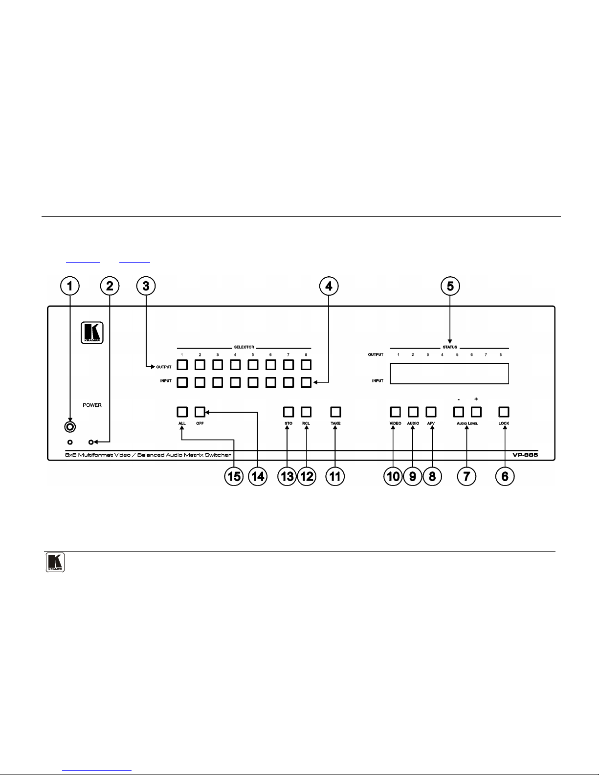
Figure 1 and Table 2 define the front panel of the VP-885.
Figure 1: VP-885 8x8 Multiformat Video/Balanced Audio Matrix Switcher Front Panel

KRAMER: SIMPLE CREATIVE TECHNOLOGY
Defining the VP-885
6
Table 2: VP-885 Front Panel Features
#
FEATURE
FUNCTION
1 IR Receiver LED lights yellow when receiving signals from the Kramer infrared
remote control transmitter
2 POWER LED LED lights green when the unit is ON
3 OUTPUT SELECTOR
Buttons
Select the output to which the input is switched
4 INPUT SELECTOR
Buttons
Select the input to switch to the output
5 INPUT STATUS Display Displays the selected input switched to the output (marked above each input)
6 LOCK Button Press to disable/enable all buttons on the front panel
7 AUDIO LEVEL Buttons Lights when pressed and actions relate to audio
8 AFV Button Lights when pressed and actions relate to the video and audio channels. The
audio channels follow the video channels
9 AUDIO Button Lights when pressed and actions relate to audio
10 VIDEO Button Lights when pressed and actions relate to video
11 TAKE Press to toggle between the Confirm mode1 and the At Once mode (see
Section 7.3
12 ) RCL Button Press the RCL button followed by an INPUT button
2
13
to recall a setup from the
non-volatile memory
STO Button Press the STO button followed by an INPUT button2 to store the current
settings
14 OFF Button An OFF-OUTPUT combination disconnects that output from the inputs; an
OFF-ALL combination disconnects all the outputs
15 ALL Button Press ALL followed by an INPUT button to connect that input to all the outputs
1 When in the Confirm mode, the TAKE button flashes
2 In this case the INPUT button corresponds to the setup address number
Defining the VP-885
7
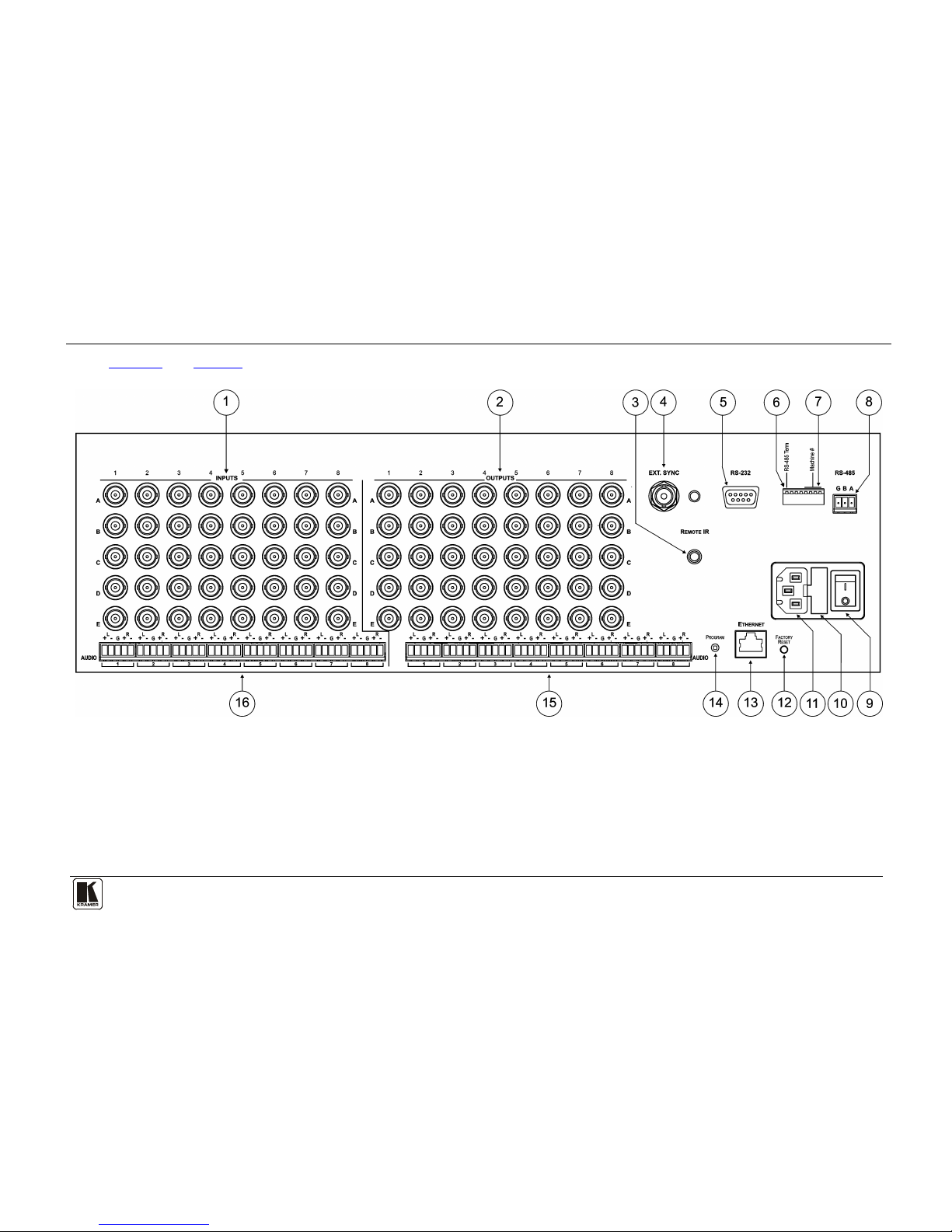
Figure 2 and Table 3 define the rear panel of the VP-885.
Figure 2: VP-885 8x8 Multiformat Video/Balanced Audio Matrix Switcher Rear Panel

KRAMER: SIMPLE CREATIVE TECHNOLOGY
Defining the VP-885
8
Table 3: VP-885 Rear Panel Features
#
FEATURE
FUNCTION
1 INPUTS BNC Connectors Connect to the composite video (Video/Y) and digital audio (S/PDIF/C)
sources, or to the s-Video (Video/Y and S/PDIF/C) sources, or to the
component video (Y, CB/PB, CR/PR) sources
2 OUTPUTS BNC
Connectors
Connect to the composite video (Video/Y) and digital audio (S/PDIF/C)
acceptors, or to the s-Video (Video/Y and S/PDIF/C) acceptors, or to the
component video (Y, CB/PB, CR/PR) acceptors
3 REMOTE IR 3.5mm Mini
Jack
Connect to an external IR receiver unit for controlling the machine via an IR
remote controller (instead of using the front panel IR receiver)
1
4 EXT. SYNC BNC
Connector
Connects to the external sync source
5 RS-232 9-pin D-sub Port Connects to the PC or the remote controller
6 RS-485 Term Switch Terminates the RS-485 if this is the only or last unit
7 Machine # DIP-switches DIP-switches for setup of the unit (1, 2 and 3 are for setting the machine
number; 4 is for RS-485 bus termination; 5 is for Reply; 8 is for RS-485 PC
communication)
8 RS-485 Port Pin G is for the Ground connection
2
9
; pins B (-) and A (+) are for RS-485
Mains Power Switch Illuminated switch for turning the unit ON and OFF
10 Mains Fuse Holder Contains the mains fuse
11 Mains Power Socket Socket for mains power cable
12 FACTORY RESET Button
Press and hold while powering up the unit to reset the audio, switching and
Ethernet settings to their factory default values:
IP address 192.168.1.39
Mask 255.255.255.0
Gateway 192.168.1.1
Audio gain for all inputs and outputs 0dB
All switching configuration Erased
Display 1, 2, 3, 4, 5, 6, 7, 8
Audio mode AFV
13 ETHERNET Connector Connects to the PC or other Serial Controller through computer networking
14 PROG Button Push in for “Program” to upgrade to the latest Kramer firmware via
RS-232, or release for “Normal” (the factory default)
15 AUDIO OUTPUTS
Terminal Block
Connectors
Connect to the balanced stereo audio acceptors
16 AUDIO INPUTS Terminal
Block Connectors
Connect to the balanced stereo audio sources
4.1 Using the IR Transmitter
You can use the RC-IR3 IR transmitter to control the machine via the built-in IR
receiver on the front panel or, instead, via an optional external IR receiver
3
1 Can be used instead of the front panel (built-in) IR receiver to remotely control the machine (see Section
. The
external IR receiver can be located up to 15 meters away from the machine. This
4.1)
2 The ground connection is sometimes connected to the shield of the RS-485 cable. In most applications, the ground is not
connected
3 Model: C-A35M/IRR-50
Installing the VP-885 in a Rack
9
distance can be extended to up to 60 meters when used with three extension cables11F1.
Connect the external IR receiver to the REMOTE IR 3.5mm connector.
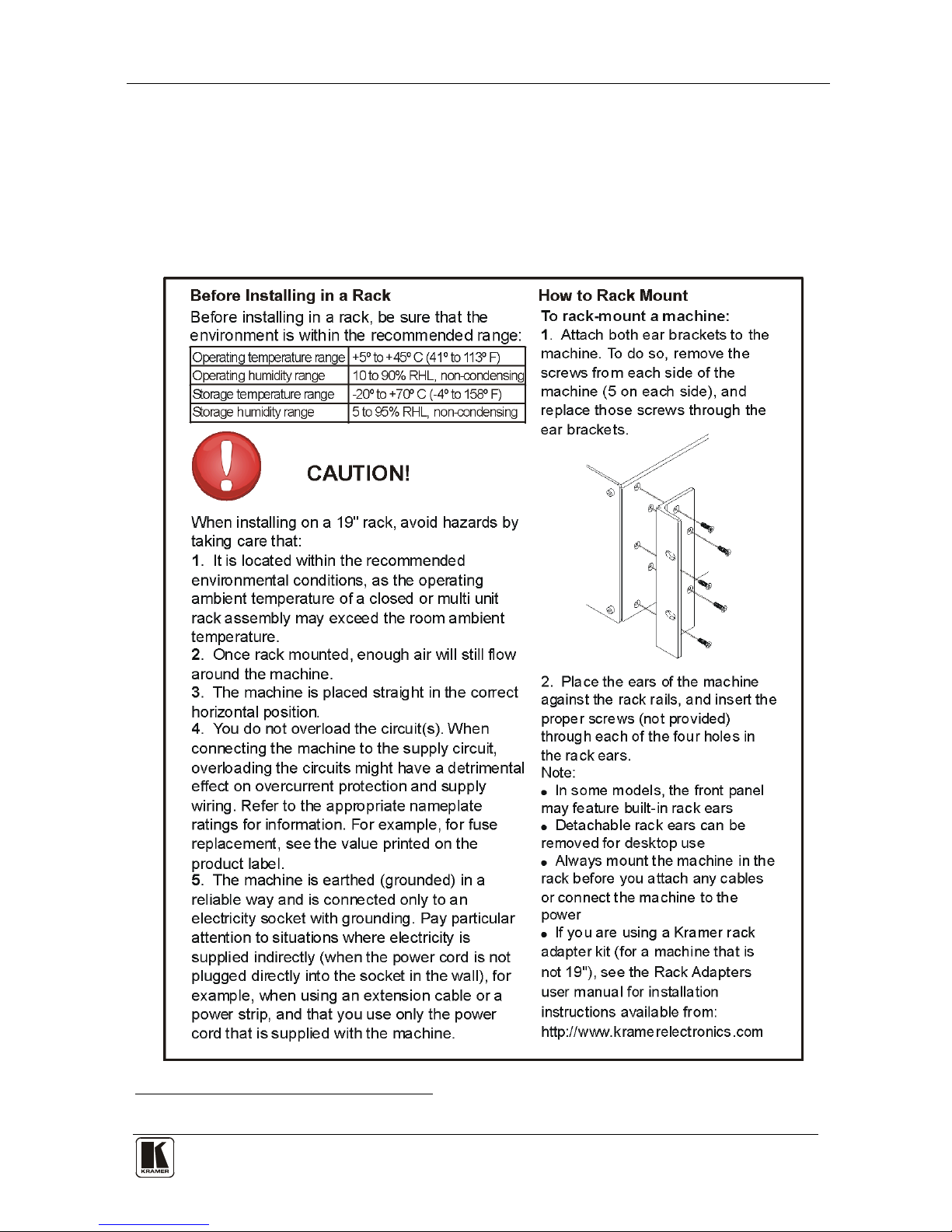
5 Installing the VP-885 in a Rack
This section describes what to do before installing in a rack and how to rack
mount the VP-885.
1 Model: C-A35M/A35F-50
KRAMER: SIMPLE CREATIVE TECHNOLOGY
Connecting the VP-885
10
6 Connecting the VP-885
This section describes how to:
• Connect audio inputs/outputs (see
Section 6.1
• Connect to the VP-885 via RS-232 (see
)
Section 6.2
• Connect to the VP-885 via RS-485 (see
)
Section 6.3
• Connect to the VP-885 via the Ethernet port and configure the Ethernet
port (see
)
Section 6.4
• Set the DIP-switches (see ) Section 6.5
To connect
)
1
the VP-885 to external devices as illustrated in the example2
in
Figure 3:
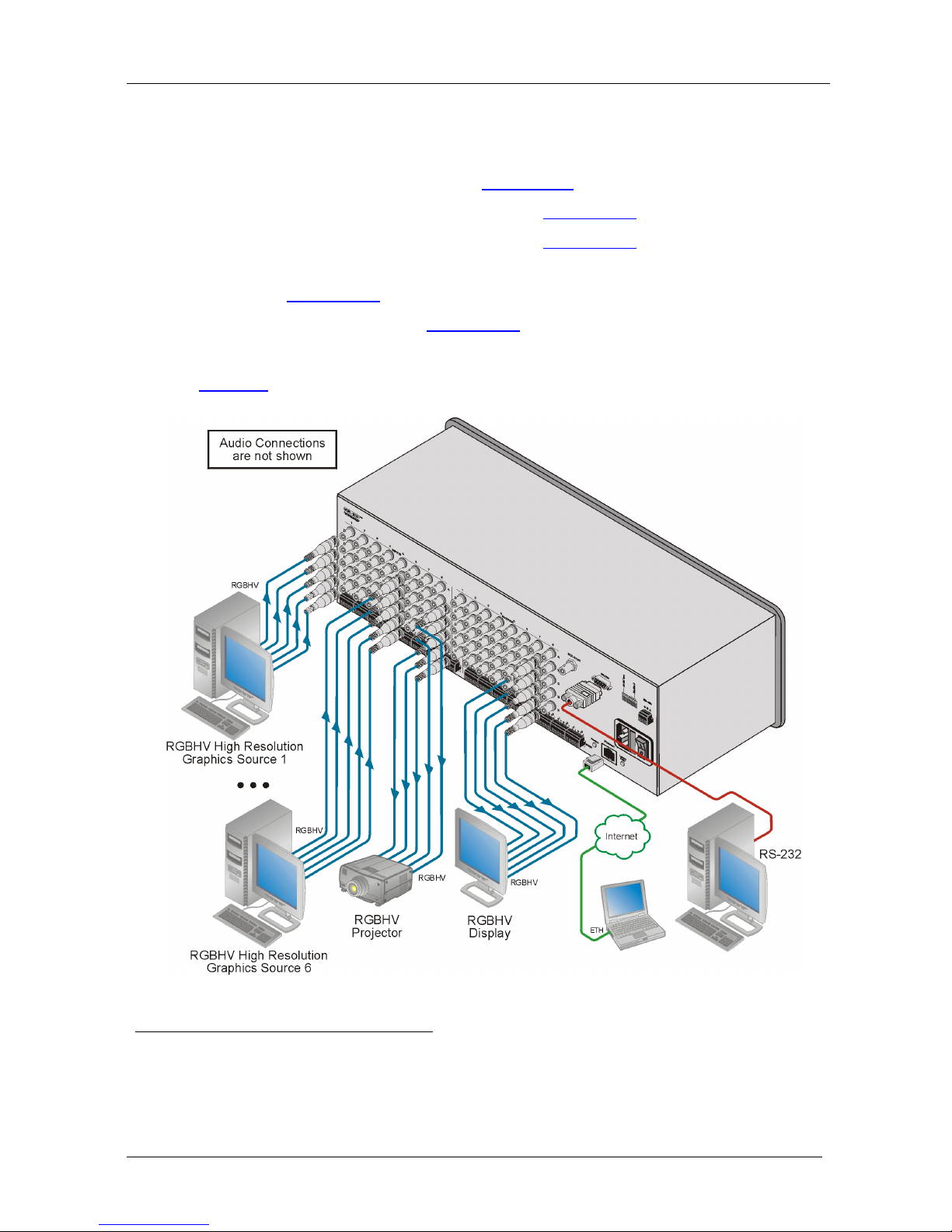
Figure 3: Connecting the VP-885
1 You do not need to connect all inputs and outputs
2 Switch OFF the power on each device before connecting it to your VP-885. After connecting your VP-885, switch on its
power and then switch on the power on each device. DO NOT push in the rear panel Flash Program “PROG” button , it is
only used for upgrading to the latest Kramer firmware
Connecting the VP-885
11
1. Connect up to 8 video sources1 to the BNC INPUT connectors
2
2. Connect up to 8 balanced stereo audio sources to the AUDIO INPUT
terminal blocks (see
.
Section 6.1
3. Connect up to 8 video acceptors to the BNC OUT connectors
).
2
.
4. Connect up to 8 balanced/unbalanced stereo audio acceptors to the
OUTPUT terminal blocks.
5. If required, connect a PC and/or controller to the:
RS-232 port (see
Section 8.1
RS-485 port (see ) Section 8.2
Ethernet port (see
)
Section 8.3
6. Connect the power cord
)
3
(not shown in Figure 3).
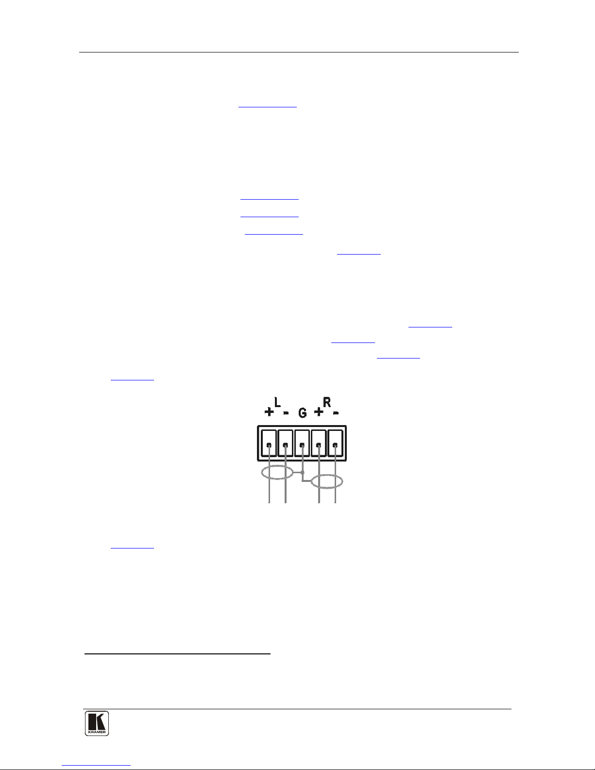
6.1 Connecting a Balanced/Unbalanced Stereo Audio Input/Output
This section describes how to wire:
• A balanced stereo audio input/output connection (see
Figure 4)
• An unbalanced stereo audio input (see
Figure 5)
• An unbalanced source to a balanced input (see
Figure 6)
Figure 4 illustrates how to wire a balanced input/output connection.
Figure 4: Wiring a Balanced Stereo Audio Input/Output
Figure 5 illustrates how to wire an unbalanced acceptor to the balanced output
of the unit.
1 All signal connections using more than one cable to interconnect between the devices should be of equal length
2 5 BNC connectors per source/acceptor
3 We recommend that you use only the power cord that is supplied with this machine
KRAMER: SIMPLE CREATIVE TECHNOLOGY
Connecting the VP-885
12
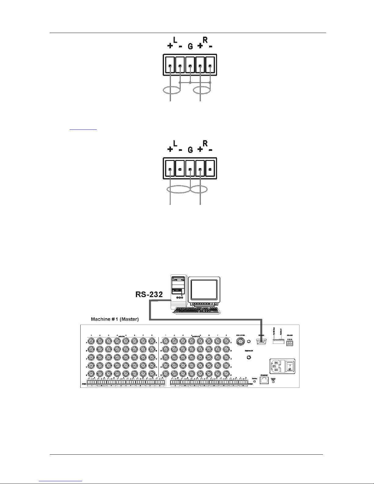
Figure 5: Wiring an Unbalanced Stereo Audio Output
Figure 6 illustrates how to wire an unbalanced source to the balanced input.
Figure 6: Wiring an Unbalanced Source to a Balanced Input
6.2 Connecting to the VP-885 via RS-232
You can connect to the VP-885 via an RS-232 connection using, for example,
a PC. Note that a null-modem adapter/connection is not required.
Figure 7: Connecting to the VP-885 via RS-232 using a PC
To connect to the VP-885 via RS-232 as illustrated in Figure 7:
• Connect the RS-232 9-pin D-sub rear panel port on the VP-885 unit via a
9-wire straight cable (pin 2 to pin 2, pin 3 to pin 3, pin 5 to pin 5) to the
RS-232 9-pin D-sub port on your PC

Connecting the VP-885
13
6.3 Connecting to the VP-885 via RS-485
You can operate the VP-885 via the RS-485 port from a distance of up to
1200m (3900ft) using any device equipped with an RS-485 port (for example,
a PC). For successful communication, you must set the RS-485 machine
number and bus termination.
To connect a device with an RS-485 port to theVP-885:
1. Connect the controller to the VP-885 as follows:
Connect the A (+) pin on the RS-485 port of the PC to the A (+) pin
on the RS-485 port on the rear panel of the VP-885
Connect the B (–) pin on the RS-485 port of the PC to the B (–) pin
on the RS-485 port on the rear panel of the VP-885
Connect the G pin on the RS-485 port of the PC to the G pin on the
RS-485 port on the rear panel of the VP-88K
2. Set the VP-885 unit to any Machine number between 2 and 16 (see
Section 6.5
3. Terminate the RS-485 line on both the VP-885 (see
).
Section 6.5
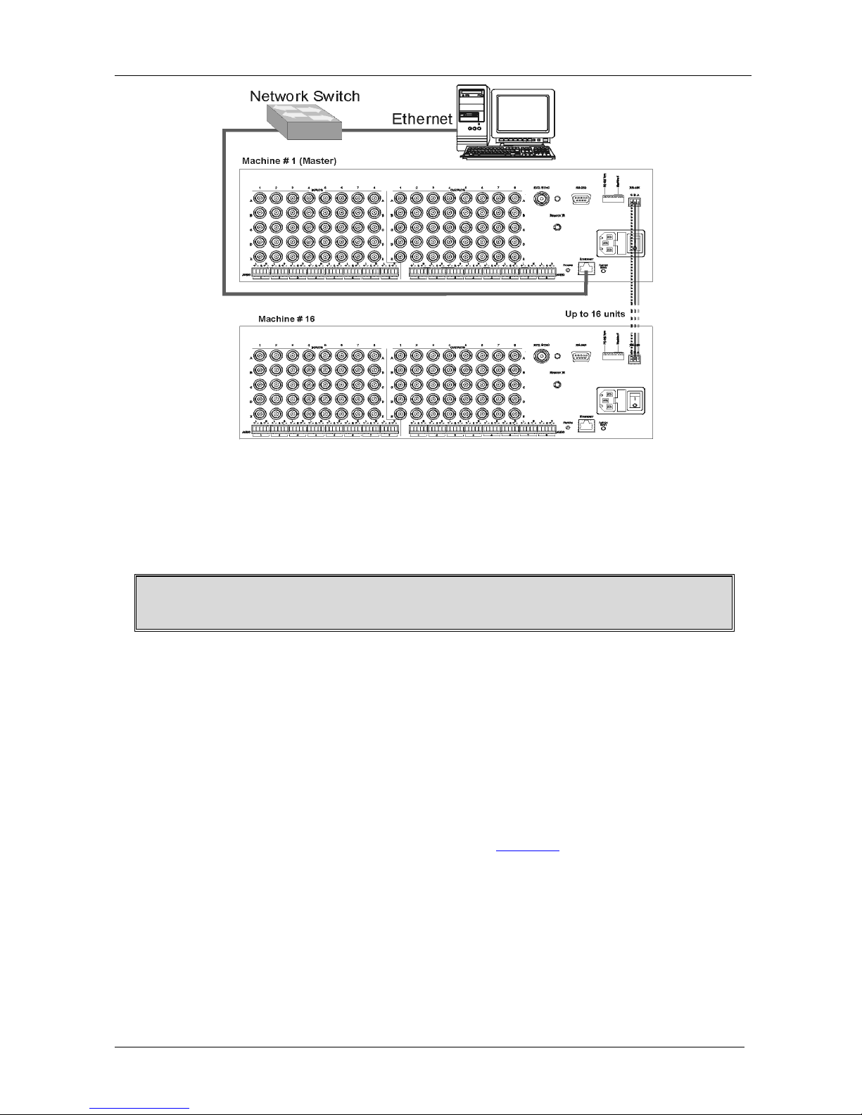
6.4 Connecting to the VP-885 via Ethernet
) and on
the controller.
You can connect to the VP-885 via Ethernet using either of the following
methods:
• Direct connection to the PC using a crossover cable (see
Section 6.4.1
• Connection via a network hub, switch, or router, using a straight-through
cable as shown in
)
Figure 8 (see Section 6.4.2
Note: The following instructions are valid only if your PC uses a fixed IP
address. If your PC receives an IP address from a DHCP server, consult with
your IT department regarding setting the IP address.
)
KRAMER: SIMPLE CREATIVE TECHNOLOGY
Connecting the VP-885
14
Figure 8: Connecting to the VP-885 via Ethernet
6.4.1 Connecting Directly via the Ethernet Port
You can connect the Ethernet port of the VP-885 to the Ethernet port on your
PC via a crossover cable with RJ-45 connectors.
This type of connection is recommended for identification of the factory
default IP Address of the VP-885 during the initial configuration
To connect the VP-885 directly to a PC using a crossover cable:
1. Using a crossover cable, connect the VP-885 to the PC via the Ethernet
port on both units.
2. On the PC, click Start > Control Panel.
3. Double-click Network Connections.
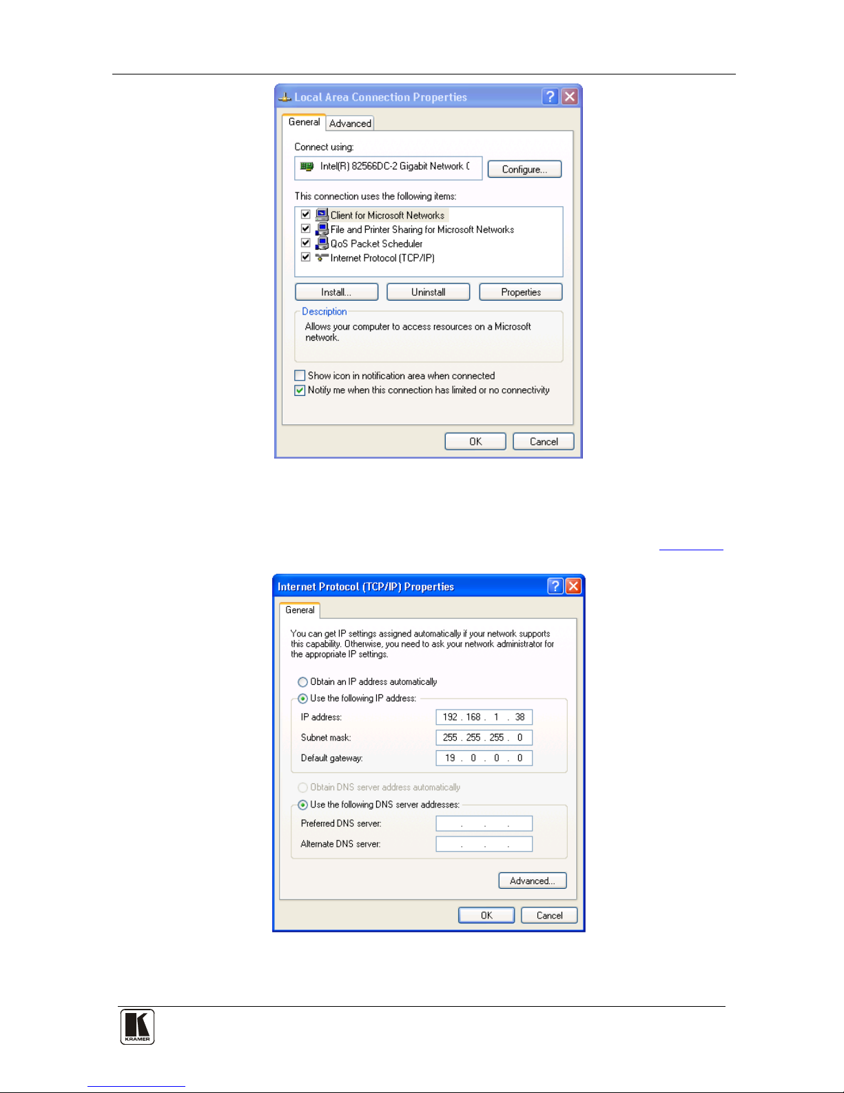
4. Right-click, and from the menu select Properties.
The Local Area Connection Properties window appears.
5. Select Internet Protocol (TCP/IP) (see
Figure 9).
Connecting the VP-885
15
Figure 9: Local Area Connection Properties Window
6. Click the Properties button.
7. Select Use the following IP address, and fill in the details as shown in
Figure 10.
Figure 10: Internet Protocol (TCP/IP) Properties Window
8. Click OK.
 Loading...