


KRAMER ELECTRONICS, LTD.
P/N: 2900-002004
KRAMER ELECTRONICS, Ltd.
USER MANUAL
MATRIX SWITCHERS
Models:
VP-88
VP-84
VP-82
VP-66
VP-64
IMPORTANT: Before proceeding, please read paragraph entitled
"Unpacking and Contents"

KRAMER ELECTRONICS, LTD.
P/N: 2900-002004
Table Of Contents
Section Name Page
1 INTRODUCTION 1
1.1 A Word on Video/Audio Switchers 1
1.2 Factors Affecting Quality of Results 1
2 SPECIFICATIONS 2
3 HOW DO I GET STARTED? 3
4 UNPACKING AND CONTENTS 3
4.1 Optional Accessories 3
5 GETTING TO KNOW YOUR MATRIX SWITCHER 3
5.1 Features of the VP-88/84/82/66/64 Matrix Switchers 3
6 INSTALLATION 6
6.1 Rack Mounting 6
7 CONNECTING TO VIDEO DEVICES 6
8 CONNECTING TO AUDIO DEVICES 6
9 USING THE SWITCHERS 7
9.1 Turning on the Machine 7
9.2 Setting Up the machine 7
9.3 Using the Front Panel Controls 7
9.3.1 Selecting an Output 7
9.3.2 Selecting an Input 7
9.3.3 Connecting Video/Audio Input/Outputs 8
9.3.4 Disconnecting Video/Audio Inputs 8
9.3.5 Connecting a Video/Audio Input to All Outputs 8
9.3.6 Selecting Video/Audio Contr ol (Breakaway) 8
9.3.7 Using the "Audio Follow Video" Mode 8
9.3.8 Storing a Configuration 8
9.3.9 Recalling a Configuration 8
9.3.10 Deleting a Setup 8
9.3.11 Using the "Take" Function 8
9.3.12 Resetting the Machine 8
9.4 Using the Back Panel Controls 8
9.4.1 Selecting the Sync Source 8
9.4.2 Setting the Configuration Switches 9
9.5 RS-232 and RS-485 Operation 9
9.6 The PC Control Software 10
9.6.1 Installation 10
9.6.2 Software Controls 11
10 TYPICAL APPLICATIONS 13
10.1 A Basic RGBHV-Audio Setup 13
11 TAKING CARE OF YOUR MATRIX SWITCHER 15
12 TROUBLESHOOTING 15
12.1 Power And Indicators 15
12.2 Video Signal 15
12.3 Audio Signal 16
12.4 Control 17
12.5 Switching Malfunctions 17
13 COMMUNICATION PROTOCOL 17
Limited Warranty 22

KRAMER ELECTRONICS, LTD.
List of Illustrations
Figure Page
1 VP-88 Front Panel Features 4
2 VP-88 Rear Panel Features 6
3 DIP switches- General View 9
4 RS-232 Control Connector Wiring 10
5 RS-232 and RS-485 Operation 10
6 Terminating the Line 10
7 Basic RGBHV-Audio Setup 14
List of Tables
Table Page
1 VP-88 Front Panel Features 4
2 VP-88 Rear Panel Features 6
3 DIP Switches Configuration 9
KRAMER ELECTRONICS, LTD.
1
1
INTRODUCTION
Congratulations on your purchase of a Kramer Electronics RGBHV/ Balanced Stereo Audio Matrix Switcher.
Since 1981 Kramer has been dedicated to the development and manufacture of high quality video/audio
equipment. The Kramer line has become an integral part of many of the best production and presentation
facilities around the world. In recent years, Kramer has redesigned and upgraded most of its line, making the
best even better. Kramer’s line of professional video/audio electronics is one of the most versatile and complete
available, and is a true leader in terms of quality, workmanship, price/performance ratio and innovation. In
addition to the Kramer line of high quality matrix switchers, such as the one you have just purchased, Kramer
also offers a full line of high quality distribution amplifiers, processors, interfaces, controllers and computerrelated products. This manual includes configuration, operation and option information of the following
RGBHV/ Balanced Stereo Audio Matrix Switchers. These VP series matrix switchers are similar in operation
and features:
VP-88: 8x8 RGBHV/ Balanced Stereo Audio Matrix
VP-84: 8x4 RGBHV/ Balanced Stereo Audio Matrix
VP-82: 8x2 RGBHV/ Balanced Stereo Audio Matrix
VP-66: 6x6 RGBHV/ Balanced Stereo Audio Matrix
VP-64: 6x4 RGBHV/ Balanced Stereo Audio Matrix
1.1 A Word on Video/Audio Switchers
A video/audio switcher switches between several sources (inputs) and one or more acceptors (outputs). A
switcher that allows several inputs to be connected to several outputs simultaneously is called a matrix switcher.
Switchers may be of the electronic or mechanical type. Most matrices are of the active electronic type, with
many crosspoints. Vertical Interval Switching, frequently used in video, ensures that the transition from one
video source to another (such as switching between two genlocked cameras) is smooth and without interference.
The switching and changeover is done during the blanked vertical interval period, when the transition is hidden
from the eyes. Vertical Interval Switching is needed when recording or transmitting a video program involving
several video sources, as in live broadcast, to ensure clean, undisturbed picture transitions. The switched sources
should be genlocked. Matrices and switchers are sometimes RS-232 or RS-485/422 controlled. Each of these
options is a way of remotely controlling a video/audio device (switcher, etc.) using a PC with a serial port, or
another device that uses a similar communication protocol. The simplest connection between the RS-232
controller and the controlled device uses two wires (TRANSMIT, RECEIVE) and a common ground wire.
Finally, the wide video bandwidth permits the matrix switchers to be used in the most demanding applications.
1.2 Factors Affecting Quality of Results
There are many factors affecting the quality of results when signals are transmitted from a source to an acceptor:
! Connection cables
- Low quality cables are susceptible to interference, they degrade signal quality due
to poor matching and cause elevated noise levels. They should therefore be of the best quality.
! Sockets and connectors of the sources and acceptors
- So often ignored, they should be of highest
quality, since "Zero Ohm" connection resistance is the target. Sockets and connectors also must match
the required impedance (75ohm in video). Cheap, low quality connectors tend to rust, thus causing
breaks in the signal path.
! Amplifying circuitry
- Must have quality performance when the desired end result is high linearity, low
distortion and low noise operation.
! Distance between sources and acceptors
- Plays a major role in the final result. For long distances
(over 15 meters) between sources and acceptors, special measures should be taken in order to avoid cable
losses. These include using higher quality cables or adding line amplifiers.
! Interference from neighboring electrical appliances
- These can have an adverse effect on signal
quality. Balanced audio lines are less prone to interference, but unbalanced audio should be installed far
from any mains power cables, electric motors, transmitters, etc. even when the cables are shielded.
KRAMER ELECTRONICS, LTD.
2
2
SPECIFICATIONS
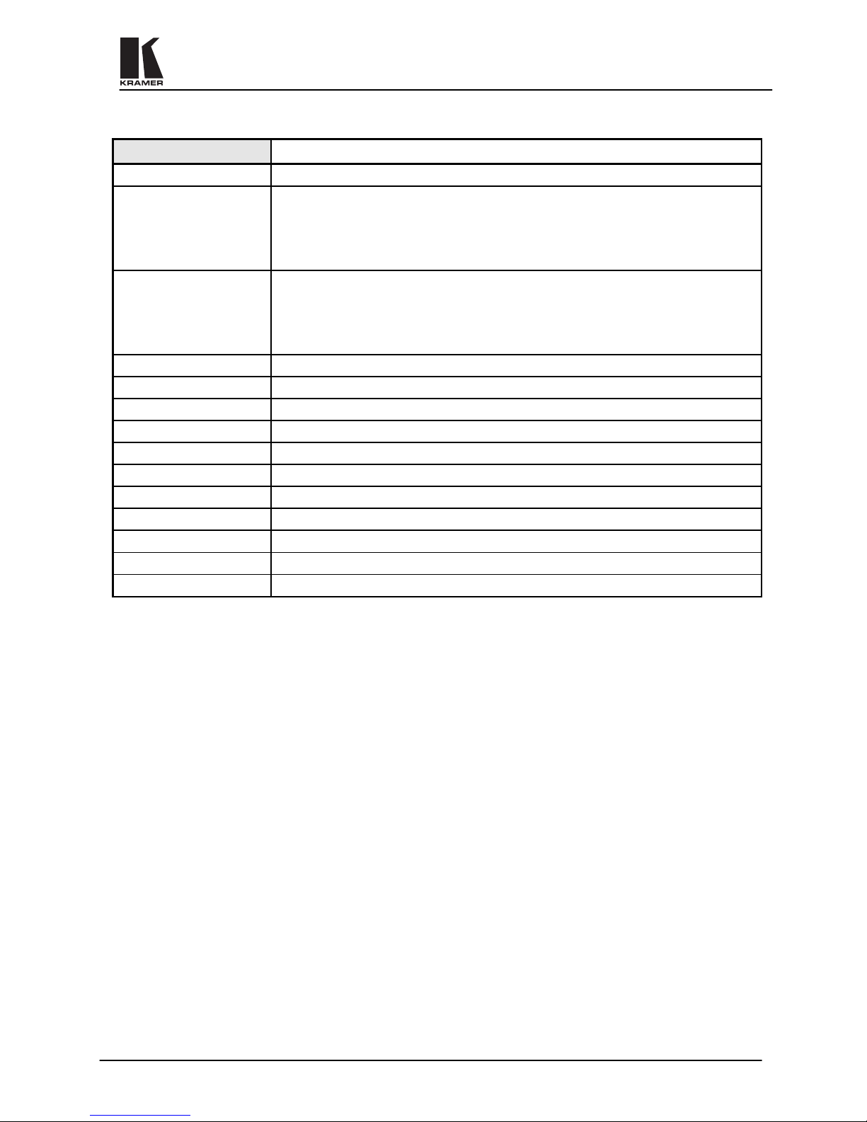
VP-88, VP-84, VP-82, VP-66, VP-64
Configuration
8x8, 8x4, 8x2, 6x6, 6x4
Inputs
8(6) x3 video (RGB): 0.7 Vpp/75ohm, on BNCs
1 Sync/Video Genlock with sync select switch 1Vpp/75ohm on a BNC.
8(6) x2 Hs & Vs, TTL level/510 ohm or Video 0.7 Vpp/75ohm, on BNCs
8(6) balanced stereo audio, +4dBm/33kohm, on detachable terminal blocks.
Outputs
8(6,4,2) x3 video (RGB): 0.7 Vpp/75ohm, on BNCs
8(6,4, 2) x2 Hs & Vs, TTL level/510 ohm or Video 0.7 Vpp/75ohm, on BNCs
8(6,4,2) balanced stereo audio, +4dBm/33kohm, on detachable terminal blocks.
Output Level
RGB: 0.7 Vpp/75ohm Audio: +4dBm/150ohm (24Vpp max.)
Video S/N Ratio
74dB
Audio S/N Ratio
84dB unweighted, (1Vpp)
Video Bandwidth
> 300MHz
Audio Bandwidth
> 100klHz.
Video Crosstalk
<-50dB @ 5MHz
Audio THD
0.025% (1V, 1kHz)
Control Type
Manual, RS-232 or RS-485
Weight
3.5 kg (7.8 lbs.) to 2.9 kg (6.4 lbs.) Approx.
Dimensions (W x D x H)
19" x 7" x 3U
Power Source
230VAC, 50/60 Hz, (115VAC, U.S.A.)

KRAMER ELECTRONICS, LTD.
3
3
HOW DO I GET STARTED?
The fastest way to get started is to take your time and do everything right the first time. Taking 15 minutes to
read the manual may save you a few hours later. You don’t even have to read the whole manual - if a certain
section doesn’t apply to you, you don’t have to spend your time reading it.
4
UNPACKING AND CONTENTS
The items contained in your Kramer accessory package are listed below. Please save the original box and
packaging materials for possible future transportation and shipment of the machine.
! Matrix Switcher
! Floppy diskettes or CD with PC control software
! AC Power cord
! This User Manual
! Kramer Concise Product Catalog/Catalog CD
! KRAMER Null Modem Adapter Connector
! 4 Rubber Feet
4.1 Optional Accessories
The following accessories, available from Kramer, can enhance implementation of your machine. For
information regarding cables and additional accessories, contact your Kramer dealer.
#
VM-1055 – a 1:5 distribution amplifier for component video (RGBHV) signals can be inserted serially
between one output of the VP Matrix and several (up to 5) RGBHV acceptors for signal distribution. The
VM-1055 has five separate channels, each of which is a high bandwidth 1:5 DA. In its typical application, it
is designed to accept a component video source such as RGBHV, RGBS or Y, R-Y, B-Y, etc., and provide
five buffered outputs to drive monitors, projectors, or other receiving devices. In addition to a typical RGBHV
application, the five channels can operate independently, allowing the unit to be used as five separate 1:5
DA’s for composite video or other formats. Bandwidth of over 300MHz ensures that the VM-1055 remains
transparent eve n in critical broad cast or high-resolutio n applications. It is housed in a rugged, professional,
rack mountable enclosure requiring only one vertical space in a standard 19” rack.
#
VP-102 (and the new VP-103) - a high performance VGA to B NC converter which is designed to allow a
single VGA/XGA source to drive a local monitor and a compatible large display device simultaneously. It can
be inserted between a VGA/XGA source (such as a PC) and the input of the matrix. Many projectors and
large monitors provide BNC connectors rather than multi-pin D connectors. The VP-102 solves this physical
incompatibility, and provides the local monitor loop-through, necessary buffering, isolation, and sync
processing for electronic compatibility. Note that the VP-102 does not
perform any scan rate conversion. The
VP-102 will accept all typical VGA modes such as VGA, SVGA, and XGA, and output RGsB, RGBS, or
RGBHV. Video bandwidth of 315MHz ensures transparent operation at multiple resolutions including XGA.
For applications not requiring a local monitor, a rear-panel termination switch is provided eliminating the
need for external termination plugs. The VP102 is rugged, depend able, and runs on stand ard 230/115VAC
via an ordinary detachable AC cord.
#
VIDEO TESTER - A new, unique, patented, indispensable tool for the video professional, the video Tester is
used to test a video path leading to/from a Matrix Switcher. By pressing only one touch switch it can trace
missing signals, distinguish between good and jittery (VCR sourced) signals, and identify the presence of
good signals. Whenever a video signal is missing, because of bad connections, cable breaks or faulty sources,
the video Tester is all you need.
#
SP-11 - (Video/Audio Processor) can be serially inserted between the Matrix Switcher and the acceptor for
video/audio processing. The SP-11 has 2 Composite video inputs and outputs, 2 Y/C (Super-Video) inputs
and outputs as well as 4 stereo-audio inputs and outputs. The SP-11 has DC coupled video inputs and outputs,
and allows full control over the video signal: Video gain down to full fade, log or linear Definition control,
log or linear Contrast control, Color saturation control, Black Level control, Red, Green and Blue controls and
a Screen Splitter control for “before-after” comparison. Input switch control is "Audio-follow-Video".
5
GETTING TO KNOW YOUR MATRIX SWITCHER
5.1 Features of the
VP-88
Matrix Switcher
Front/Rear panel features of the
VP-88
are shown in Figure 1, and Figure 2 and are described in Table 1 and
Table 2. The VP-88 is shown as a n example, but the same applies to all the matrices in this group.
KRAMER ELECTRONICS, LTD.
4
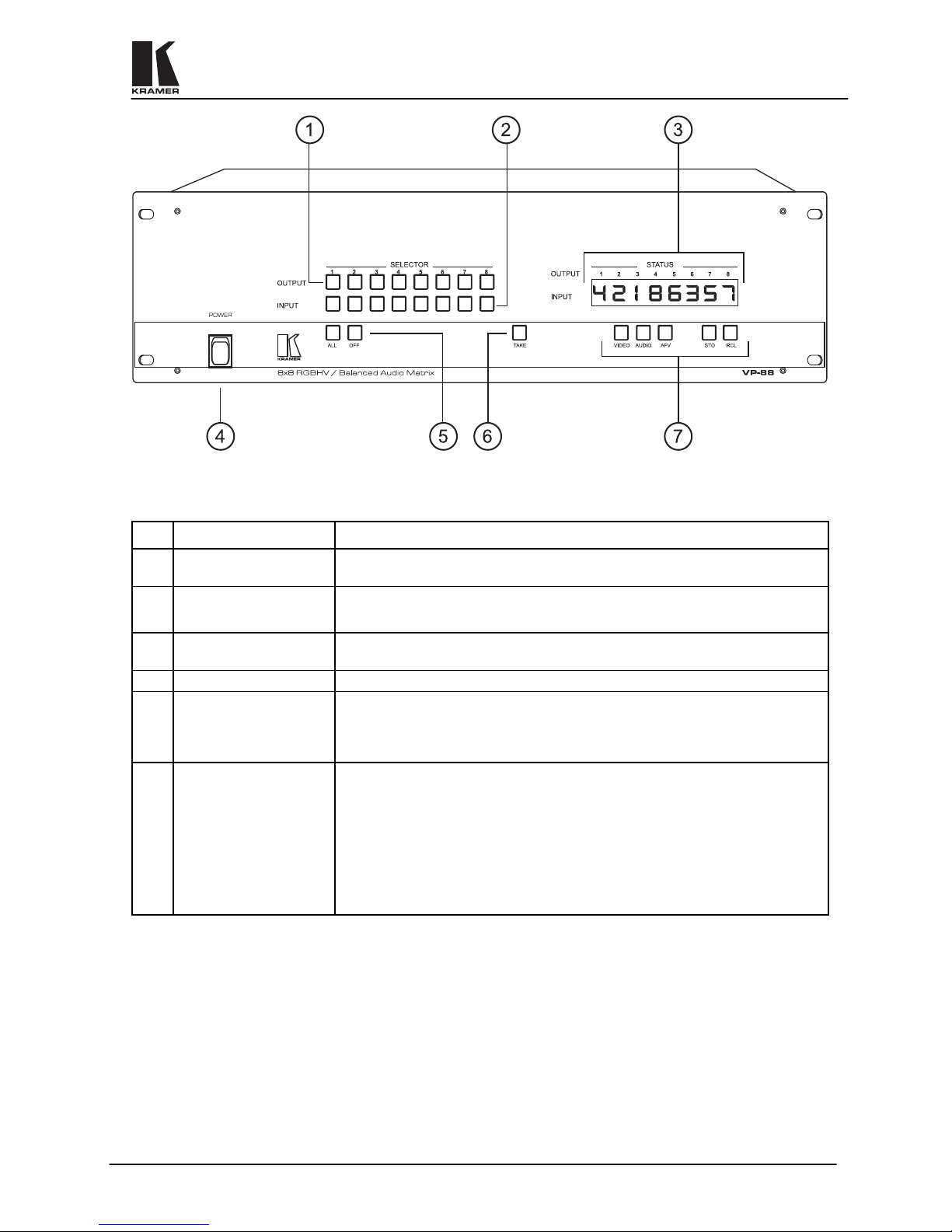
Figure 1: VP-88 Front Panel Features
Table 1: VP-88 Front Panel Features
No.
Feature
Function
1.
OUTPUT SELECTOR
buttons
Select the desired output that the input signal is switched to.
2.
INPUT SELECTOR
buttons
Select the desired input to be switched to the output.
3.
INPUT STATUS
display
Displays the selected input switched to the output (marked above each input).
4.
Power switch Illuminated switch supplies power to the unit.
5.
All and OFF controls Press ALL, then an input button, to connect that audio/video input to all
audio/video outputs. When OFF is pressed after pushing an output button, that
video/audio output is disconnected from the video/audio input. To disconnect all
the outputs, press ALL then OFF.
6.
TAKE
The machines can operate either in "Normal" (no user confirmation for each
action is needed) mode or in "Take" mode. In "Take Mode", any action causes
the TAKE button to blink before implementation, and TAKE must be pressed
again in order to implement the operation. Pressing the TAKE button toggles
the mode. The button illuminates when in "Take Mode".
NOTE
To cancel any operation in itiated by pressing a button, press th e same button
again.
KRAMER ELECTRONICS, LTD.
5
Table 1: VP-88 Front Panel Features (Cont.)
7.
Additional Control
Switches
VIDEO: When pressed, illuminates and selects the video mode (Breakaway) to
enable modification of the video crosspoints.
AUDIO: When pressed, illuminates and selects the audio mode (Breakaway) to
enable modification of the audio crosspoints.
AFV: When pressed, illuminates and selects the "Audio Follow Video"
function. If the audio configura tion differs from the video configuration, the
INPUT STATUS display flashes the audio outputs that are to be reconfigured
for AFV operation. In that case, the TAKE button must be pressed to confirm
the modification.
STO: Should be pressed, followed by an input or output pushbutton to store the
current status in the non-volatile memory. For example. Press STO followed by
INPUT 4 button to store Setup#4 in the non-volatile memory.
NOTE: To delete a setup from the memory, press the STO and RCL buttons
simultaneously, followed by the input button (Setup number) to be deleted.
RCL: Should be pressed, followed by input or output pushbutton to select a
predetermined setup (1-8 available setups). For example, press RCL followed by
INPUT 4 button to recall Setup#4 from the non-volatile memory.
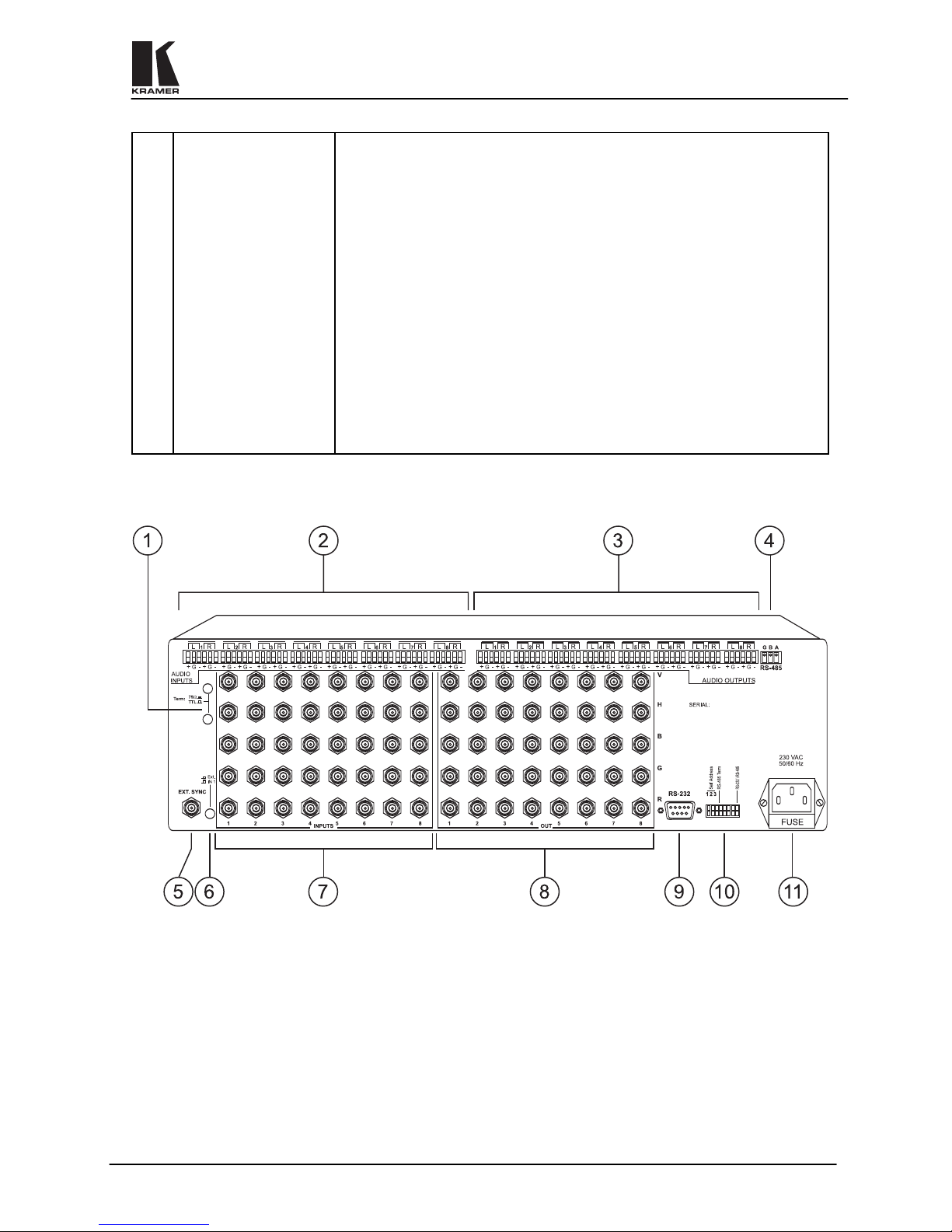
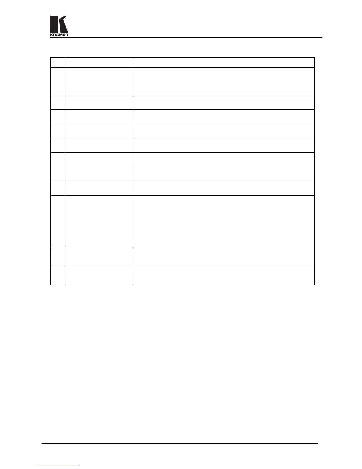
Figure 2: VP-88 Rear Panel Features
KRAMER ELECTRONICS, LTD.
6
Table 2: VP-88 Rear Panel Features
No.
Feature
Function
1.
H & V Channels
termination switches
These switches, when released, allow the upper input channels to be used for
TTL level H & V sync signals (RGBHV operation). When pressed - the input
channels become analog video channels, the same as the lower RGB channels,
and the machine can be used for 5 identical video channels.
2.
1-8 AUDIO INPUTS
terminal blocks
Audio inputs used to connect the balanced stereo audio input sources.
3.
1-8 AUDIO OUTPUTS
terminal blocks
Audio outputs used to connect the balanced stereo audio output acceptors.
4.
RS-485 terminal block Used for bi-directional communication with another Matrix Switcher or PC
through the RS-485 interface.
5.
EXT. SYNC BNC
connector
Used to connect an external video sync input. The external sync input is
selected by the SYNC Select switch.
6.
SYNC Select switch Selects either an external sync, from the external source, or internal sync,
which is normally inputted via the VIDEO INPUT #1 connector.
7.
VIDEO INPUTS BNC
connectors
Video inputs used to connect the video sources.
8.
VIDEO OUTPUTS BNC
connectors
Video outputs used to connect the video acceptors.
9.
DB-9 female RS-232
connector
Used to control the Matrix Switcher (see section 9.4 for more details
concerning RS-232 operation) from a PC, or remote control device, through an
RS-232 interface and a null-modem adapter (provided with the machine).
NOTE
Operation of the
machine
from a remote PC
may be done using the K-Switch control
Software (provided with the
machine)
.
10.
Setup DIP switches Allow proper configuration of the control signals received and transmitted
through the RS-232 (or RS-485) control port, master/slave modifications, line
termination and device ID numbers.
11.
Power Connector
A 3-prong AC connector allows power to be supplied to the unit. Directly
underneath this connector, a fuse holder houses the appropriate fuse.
6
INSTALLATION
6.1 Rack Mounting
The VP-88 may be rackmounted in a standard 19” (3U) EIA rack assembly and includes rack “ears” at the ends
of the front panel. This device does not require spacing above or below the unit for ventilation. To rack mount
the VP-88, simply place the unit’s rack ears against the rails of the rack, and insert standard scre ws through each
of the four corner holes in the rack ears.
7
CONNECTING TO VIDEO DEVICES
Video / RGBHV sources and output devices may be connected to the VP-88 through the BNC type connec tors
located on the back of the unit. W hen using the matrix for RGBHV signals, all signal connections that use more
than one cable interconnecting between devices should be of equal length. (Example: cables between a PC and
the machine should be equal in length).
8
CONNECTING TO AUDIO DEVICES
Audio sources and output d evices (such as a mplifiers or reco rders) are co nnected to the machines t hrough the
terminal block connectors located at the back of the machines.
 Loading...