

Kramer VP-81K User Manual

KRAMER ELECTRONICS LTD.
USER MANUAL
MODEL:
VP-81K
8x1
UXGA/Audio Switcher
P/N: 2900-000387 Rev 3

VP-81K – Contents i
Contents
1 Introduction 1
2 Getting Started 2
2.1 Achieving the Best Performance 2
3 Overview 3
3.1 DDC Support 4
3.2 Defining EDID 4
3.3 Defining the VP-81K 8x1 UXGA/Audio Switcher 4
3.4 Using the IR Transmitter 7
4 Installing in a Rack 8
5 Connecting the VP-81K 9
5.1 Connecting the Balanced/Unbalanced Stereo Audio Output 10
5.2 Controlling via RS-232 11
5.3 Connecting a PC or Controller to the RS-485 Port 12
5.4 Controlling the VP-81K via the Ethernet Port 12
5.5 DIP-Switch Settings 18
5.6 Cascading Machines 18
6 Operating Your VP-81K 8x1 UXGA/Audio Switcher 20
6.1 Using the Front Panel Input Selector Buttons 20
6.2 Using the Regular or Automatic Switching Mode 20
6.3 Using the Audio-Follow-Video/Breakaway Modes 21
6.4 Setting the Audio Gain 22
7 Technical Specifications 23
8 Communication Parameters 24
9 Table of ASCII Codes for Serial Communication (Protocol 3000) 25
10 Table of Hex Codes for Serial Communication (Protocol 2000) 26
11 Kramer Protocol 28
11.1 Switching Protocols 28
11.2 Kramer Protocol 3000 29
11.3 Kramer Protocol 2000 36
Figures
Figure 1: VP-81K 8x1 UXGA/Audio Switcher Front Panel 5
Figure 2: VP-81K 8x1 UXGA/Audio Switcher Rear Panel 6
Figure 3: Connecting the VP-81K 10
Figure 4: Connecting an Balanced Stereo Audio Output 10
Figure 5: Connecting an Unbalanced Output 10
Figure 6: Crossed Cable RS-232 Connection 11
Figure 7: Straight Cable RS-232 Connection with a Null Modem Adapter 11
Figure 8: Local Area Connection Properties Window 13
Figure 9: Internet Protocol (TCP/IP) Properties Window 13
Figure 10: Connect Screen 14
Figure 11: Device Properties Screen 15
Figure 12: HOME Embedded Web Page 16
Figure 13: CONFIGURATIONS Embedded Web Page 17
Figure 14: SETUP DIP-Switches 18
Figure 15: Control Configuration via RS-232 and RS-485 19

VP-81K - Introduction 1
1 Introduction
Welcome to Kramer Electronics! Since 1981, Kramer Electronics has been
providing a world of unique, creative, and affordable solutions to the vast range of
problems that confront the video, audio, presentation, and broadcasting
professional on a daily basis. In recent years, we have redesigned and upgraded
most of our line, making the best even better!
Our 1,000-plus different models now appear in 11 groups that are clearly defined
by function: GROUP 1: Distribution Amplifiers; GROUP 2: Switchers and Matrix
Switchers; GROUP 3: Control Systems; GROUP 4: Format/Standards Converters;
GROUP 5: Range Extenders and Repeaters; GROUP 6: Specialty AV Products;
GROUP 7: Scan Converters and Scalers; GROUP 8: Cables and Connectors;
GROUP 9: Room Connectivity; GROUP 10: Accessories and Rack Adapters and
GROUP 11: Sierra Products.
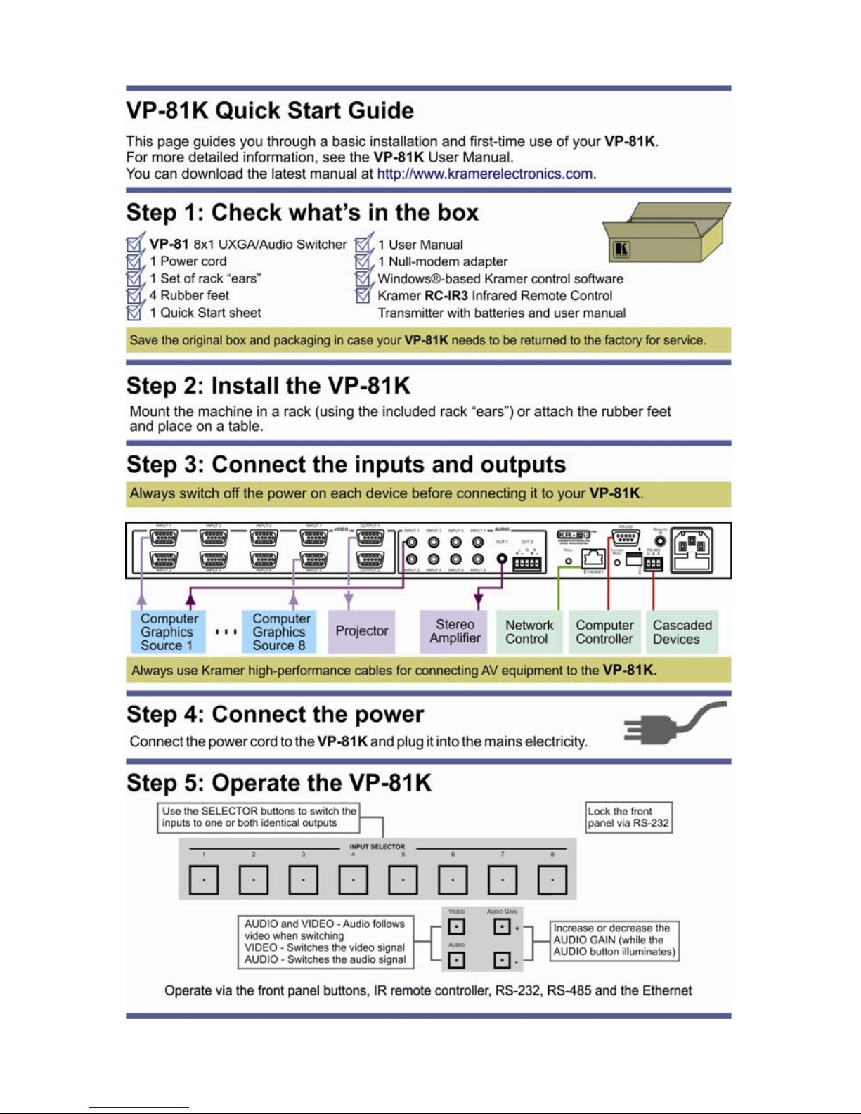
Congratulations on purchasing your Kramer VP-81K 8x1 UXGA/Audio Switcher,
which is ideal for the following typical applications:
Display systems requiring simple input selection
Remote monitoring of computer activity in schools and businesses
Rental/staging applications
Multimedia and presentation source selection

2 VP-81K - Getting Started
2 Getting Started
We recommend that you:
Unpack the equipment carefully and save the original box and packaging
materials for possible future shipment
Review the contents of this user manual
Use Kramer high performance high resolution cables
Use only the power cord that is supplied with this machine
Go to http://www.kramerelectronics.com to check for up-to-date
user manuals, application programs, and to check if firmware
upgrades are available (where appropriate).
2.1 Achieving the Best Performance
To achieve the best performance:
Use only good quality connection cables to avoid interference, deterioration
in signal quality due to poor matching, and elevated noise levels (often
associated with low quality cables)
Avoid interference from neighboring electrical appliances that may adversely
influence signal quality
Position your Kramer VP-81K away from moisture, excessive sunlight and
dust
i

VP-81K - Overview 3
3 Overview
The VP-81K is a high-performance switcher for computer graphics video signals,
with resolutions up to and exceeding UXGA, and unbalanced stereo audio signals.
The unit can switch any one of eight inputs to two identical video outputs, one
balanced and one unbalanced stereo audio outputs.
The VP-81K features:
Very high video bandwidth, ensuring transparent UXGA performance
Audio-follow-video (AFV) in which all operations relate to both the video and
the audio channels, or audio breakaway option, in which video and audio
channels switch independently
Volume control
DDC (Display Data Channel) communication between the selected input and
output 1 high-density 15-pin HD connectors on pins 12 and 15
KR-ISP™ technology, innovative integrated sync processing that lets you
achieve a sharp, stable image even when the sync level is too low, by
restoring the sync signal waveform
The cascade of up to eight units with control from a PC or serial controller
Automatic switching mode (as well as the regular switching mode),
automatically switching to the lowest number input when that input is
connected and active
For example, if INPUT 6 is currently selected and connected and then INPUT 4
receives an active signal, the VP-81K automatically switches to INPUT 4.
Control the VP-81K using the front panel buttons, or remotely via:
RS-485 or RS-232 serial commands transmitted by a touch screen system,
PC, or other serial controller
Ethernet
The Kramer RC-IR3 Infrared Remote Control Transmitter or infrared remote
extension cable transmitter (optional)

4 VP-81K - Overview
3.1 DDC Support
When establishing a VGA connection between a PC or laptop and a display device, a
set of parameters known as EDID is exchanged between them, which is carried over
the DDC channel. In some PC graphic cards and laptops, this information exchange is
essential for proper VGA OUT operation.
3.2 Defining EDID
The Extended Display Identification Data (EDID) is a data-structure provided by a
display, to describe its capabilities to a graphics card (that is connected to the
display’s source). The EDID enables the VP-81K to “know” what kind of monitor is
connected to the output. The EDID includes the manufacturer’s name, the product
type, the timing data supported by the display, the display size, luminance data
and (for digital displays only) the pixel mapping data.
EDID is defined by a standard published by the Video Electronics Standards
Association (VESA).
3.3 Defining the VP-81K 8x1 UXGA/Audio Switcher
This section defines the VP-81K.
VP-81K – Overview 5
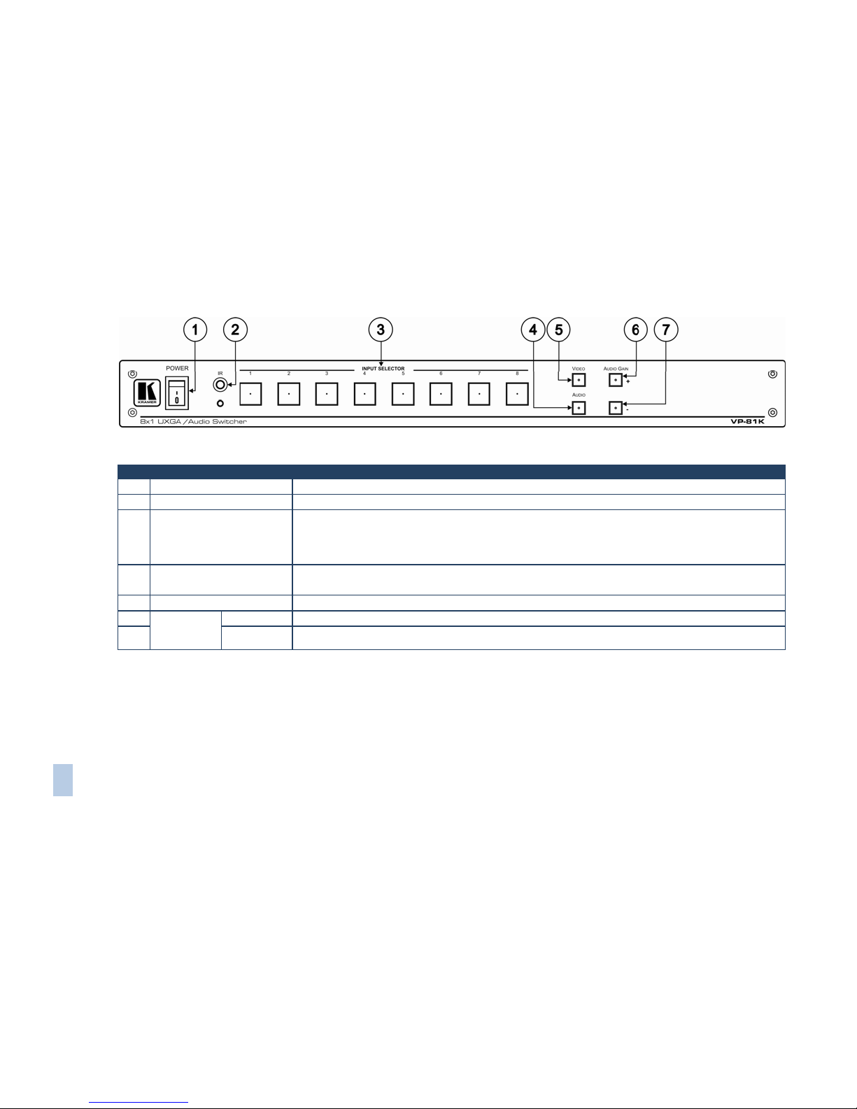
Figure 1: VP-81K 8x1 UXGA/Audio Switcher Front Panel
# Feature Function
1 POWER Switch Illuminated switch supplying power to the unit
2 IR Receiver The yellow LED is illuminated when receiving signals from the Kramer Infrared remote control transmitter
3 INPUT SELECTOR Buttons Select the input (from 1 to 8) to switch to the outputs
The button illuminates in red if it is selected and there is no input signal
The button illuminates in green if it is not selected but there is an input signal at that input
The button illuminates in violet if it is selected and there is an input signal connected
4 AUDIO Button When illuminated, actions relate to audio
If the AUDIO and VIDEO buttons both illuminate, the unit operates in the audio-follow-video mode
5 VIDEO Button When illuminated, actions relate to video
6
AUDIO
GAIN
Buttons
+ Press to increase the audio output level of the selected input (while the AUDIO button illuminates)
7 - Press to decrease the audio output level of the selected input
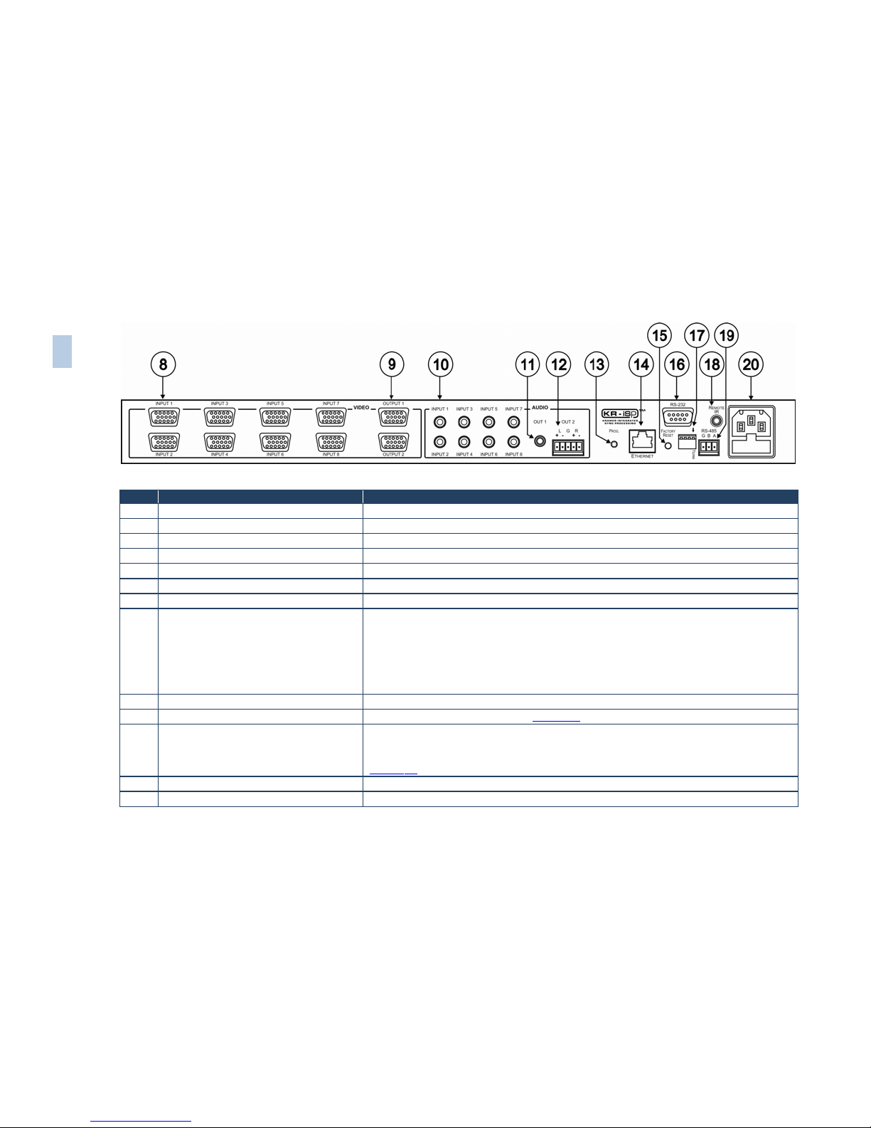
Figure 2: VP-81K 8x1 UXGA/Audio Switcher Rear Panel
# Feature Function
8 INPUT 15-pin HD Connectors Connect to the UXGA sources (from 1 to 8)
9 OUTPUT 15-pin HD Connectors Connect to the UXGA acceptors (from 1 to 2)
10 AUDIO INPUT Mini Plug Connectors Connect to the unbalanced stereo audio sources (from 1 to 8)
11 OUT 1 Mini Plug Connector Connect to the unbalanced stereo audio acceptor
12 OUT 2 Terminal Block Connector Connect to the balanced stereo audio acceptor
13 PROG. Button Not used (for technical staff use only)
14 Ethernet Connector Connects to the PC or other Serial Controller through computer networking
15 FACTORY RESET Button
Press to reset to factory default definitions:
IP number 192.168.1.39
Mask – 255.255.255.0
Gateway – 192.168.1.1
The audio gain of all the inputs is reset to 0dB
Turn the machine OFF, then turn the machine ON while pressing the FACTORY RESET button.
The unit powers up and loads its memory with the factory default definitions
16 RS-232 9-pin D-sub Port Connects to the RS-232 9-pin D-sub port of the next unit in the daisy-chain
17 SETUP DIP-switches DIP-switches for setup of the unit, see Section 5.5
18 REMOTE IR 3.5mm Mini Jack
Connect to an external IR receiver unit for controlling the machine via an IR remote controller
(instead of using the front panel IR receiver)
Can be used instead of the front panel (built-in) IR receiver to remotely control the machine, see
Section
3.4
19 RS-485 Detachable Terminal Block Port Pin # 1 is for ground connection, and Pins # 2 and # 3 are for RS-485
20 Power Connector with Fuse AC connector enabling power supply to the unit
6 VP-81K – Overview

VP-81K - Overview 7
3.4 Using the IR Transmitter
You can use the RC-IR3 IR transmitter to control the machine via the built-in IR
receiver on the front panel or, instead, via an optional external IR receiver (Model:
C-A35M/IRR-50). The external IR receiver can be located up to 15 meters away
from the machine. This distance can be extended to up to 60 meters when used
with three extension cables (Model: C-A35M/A35F-50).
Before using the external IR receiver, be sure to arrange for your Kramer dealer to
insert the internal IR connection cable (P/N: 505-70434010-S) with the 3.5mm
connector that fits into the REMOTE IR opening on the rear panel. Connect the
external IR receiver to the REMOTE IR 3.5mm connector.
8 VP-81K - Installing in a Rack
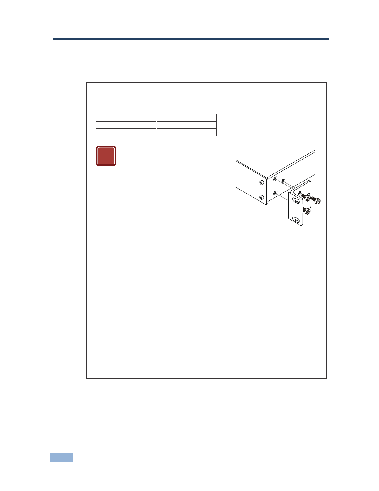
4 Installing in a Rack
This section provides instructions for rack mounting the unit.
Before Installing in a Rack How to Rack Mount
Before installing in a rack, be sure that the
environment is within the recommended range:
To rac k -mount a machine:
1
. Attach both ear brackets to the
machine. To do so, remove the
screws from each side of the
machine (3 on each side), and
replace those screws through the
ear brackets.
When installing on a 19" rack, avoid hazards by
taking care that:
. It is located within the recommended
environmental conditions, as the operating
ambient temperature of a closed or multi unit
rack assembly may exceed the room ambient
temperature.
. Once rack mounted, enough air will still flow
around the machine.
. The machine is placed straight in the correct
horizontal position.
. You do not overload the circuit(s). When
connecting the machine to the supply circuit,
overloading the circuits might have a detrimental
effect on overcurrent protection and supply
wiring. Refer to the appropriate nameplate
ratings for information. For example, for fuse
replacement, see the value printed on the
product label.
. The machine is earthed (grounded) in a
reliable way and is connected only to an
electricity socket with grounding. Pay particular
attention to situations where electricity is
supplied indirectly (when the power cord is not
plugged directly into the socket in the wall), for
example, when using an extension cable or a
power strip, and that you use only the power
cord that is supplied with the machine.
1
2
3
4
5
2. Place the ears of the machine
against the rack rails, and insert the
proper screws (not provided)
through each of the four holes in
the rack ears.
Note:
In some models, the front panel
may feature built-in rack ears
Detachable rack ears can be
removed for desktop use
Always mount the machine in the
rack before you attach any cables
or connect the machine to the
power
If you are using a Kramer rack
adapter kit (for a machine that is
not 19"), see the Rack Adapters
user manual for installation
instructions available from:
http://www.kramerelectronics.com)
CAUTION!
OPERATING TEMPERATURE:
STORAGE TEMPERATURE:
HUMIDITY:
0º to +55ºC (32º t o 131ºF)
-45º to +72ºC (-49º to 162ºF)
10% to 90%, RHL n on-condensing
!

VP-81K - Connecting the VP-81K 9
5 Connecting the VP-81K
Always switch off the power to each device before connecting it to your
VP-81K. After connecting your VP-81K, connect its power and then
switch on the power to each device.
To connect the VP-81K, as illustrated in the example in Figure 3
, do the following:
1. Connect up to eight UXGA computer graphics sources to the INPUT 15-pin
HD connectors (from 1 to 8).
You do not have to connect all the inputs.
2. Connect the unbalanced audio sources to up to eight INPUT mini plug
connectors.
Not shown in Figure 3.
3. Connect the 15-pin HD OUTPUT connectors (from 1 to 2) to up to two UXGA
acceptors (for example, a projector to OUTPUT 1 and a display to OUTPUT 2).
You do not have to connect both outputs.
4. Connect the OUT 1 unbalanced audio mini plug connector to an audio
acceptor.
5. Connect the OUT 2 balanced audio terminal block connector (see Section
5.1
) to an audio acceptor.
6. Set the DIP-switches (see Section
5.5).
7. As an option you can connect a PC and/or controller to the:
RS-232 port (see Section
5.2)
RS-485 port (see Section 5.3)
The Ethernet connector (see Section 5.4)
8. Connect the power cord.
We recommend that you use only the power cord that is supplied with this machine.
i

10 VP-81K - Connecting the VP-81K
Figure 3: Connecting the VP-81K
5.1 Connecting the Balanced/Unbalanced Stereo Audio
Output
This section illustrates how to wire a balanced output connection (see Figure 4)
and an unbalanced audio output (see Figure 5
).
Figure 4: Connecting an
Balanced Stereo Audio
Output
Figure 5: Connecting an
Unbalanced Output
VP-81K - Connecting the VP-81K 11
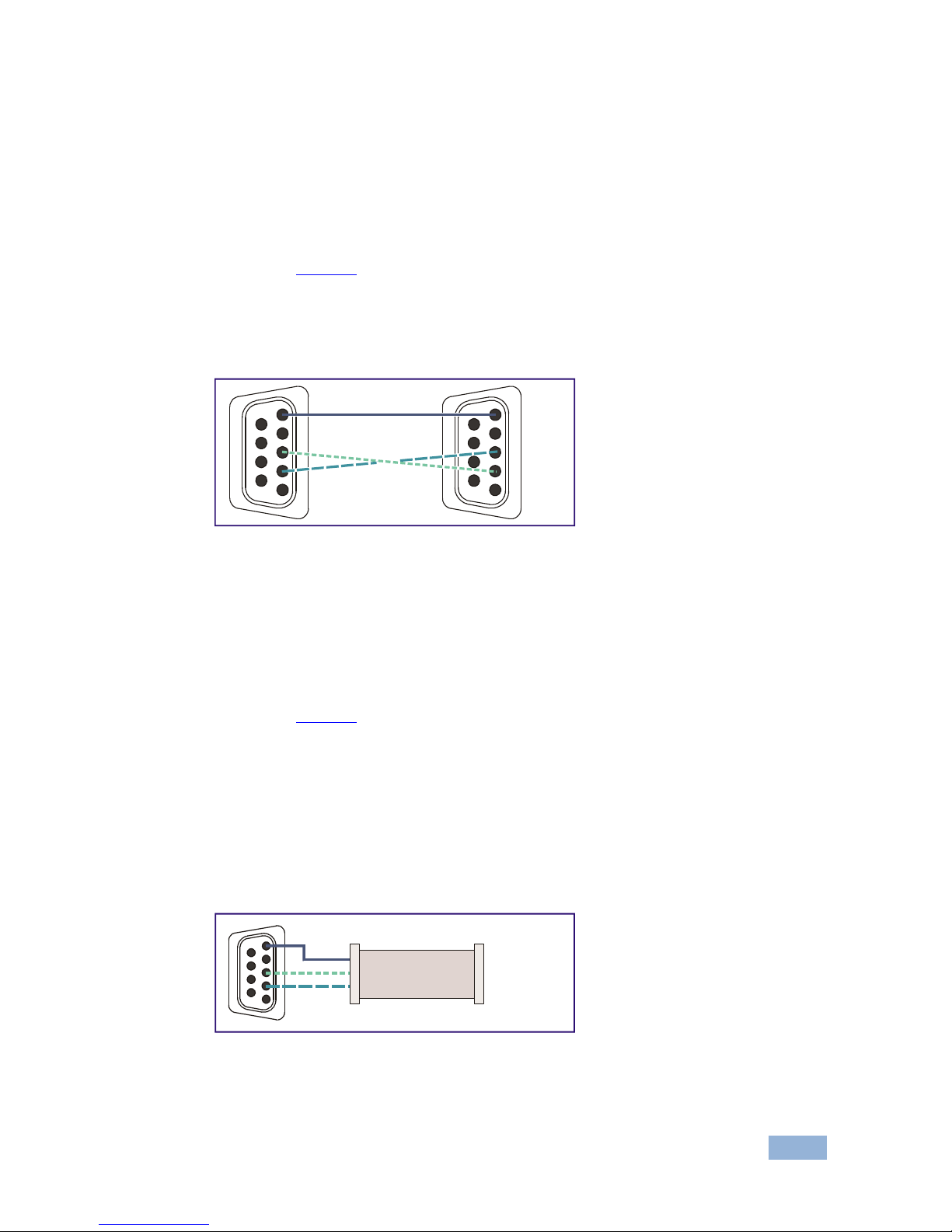
5.2 Controlling via RS-232
You can connect to the unit via a crossed RS-232 connection, using for example,
a PC. A crossed cable or null-modem is required as shown in method A and B
respectively. If a shielded cable is used, connect the shield to pin 5.
Method A (Figure 6
)—Connect the RS-232 9-pin D-sub port on the unit via a
crossed cable (only pin 2 to pin 3, pin 3 to pin 2, and pin 5 to pin 5 need be
connected) to the RS-232 9-pin D-sub port on the PC.
Note: There is no need to connect any other pins.
Figure 6: Crossed Cable RS-232 Connection
Hardware flow control is not required for this unit. In the rare case where a
controller requires hardware flow control, short pin 1 to 7 and 8, and pin 4 to 6 on
the controller side.
Method B (Figure 7
)—Connect the RS-232 9-pin D-sub port on the unit via a
straight (flat) cable to the null-modem adapter, and connect the null-modem
adapter to the RS-232 9-pin D-sub port on the PC. The straight cable usually
contains all nine wires for a full connection of the D-sub connector. Because the
null-modem adapter (which already includes the flow control jumpering described
in Method A above) only requires pins 2, 3 and 5 to be connected, you are free to
decide whether to connect only these 3 pins or all 9 pins.
Figure 7: Straight Cable RS-232 Connection with a Null Modem Adapter
1
2
6
3
7
4
8
5
9
1
2
6
3
7
4
8
5
9
PC
1
2
6
3
7
4
8
5
9
to PC
Null-Modem
Adapter
 Loading...