

Kramer VP-797, VP-796A, VP-796, VP-798, VP-797A Operating Instructions Manual
...
PDF provided by Conference Room AV
Kramer VP-796A 9x4 4K UHD HDBaseT, Presentation Switcher Scaler, Analog Audio
VP-796(A) / VP-797(A) / VP-798(A)
Operating Instructions

COPYRIGHT
This document and the software described within it are copyrighted with all rights reserved. Under
copyright laws, neither the documentation nor the software may be copied, photocopied, reproduced,
translated, or reduced to electronic medium or machine readable form, in whole or in part, without
prior written consent of Kramer UK Ltd ("Kramer"). Failure to comply with this condition may result in
prosecution.
Kramer does not warrant that this product package will function properly in every hardware/software
environment.
Although Kramer has tested the hardware, firmware, software and reviewed the documentation,
KRAMER MAKES NO WARRANTY OR REPRESENTATION, EITHER EXPRESS OR IMPLIED, WITH RESPECT TO
THIS HARDWARE, FIRMWARE, SOFTWARE OR DOCUMENTATION, THEIR QUALITY, PERFORMANCE,
MERCHANTABILITY, OR FITNESS FOR A PARTICULAR PURPOSE. THIS SOFTWARE AND DOCUMENTATION
ARE LICENSED 'AS IS', AND YOU, THE LICENSEE, BY MAKING USE THEREOF, ARE ASSUMING THE ENTIRE
RISK AS TO THEIR QUALITY AND PERFORMANCE.
IN NO EVENT WILL KRAMER BE LIABLE FOR DIRECT, INDIRECT, SPECIAL, INCIDENTAL, OR
CONSEQUENTIAL DAMAGES ARISING OUT OF THE USE OR INABILITY TO USE THE SOFTWARE OR
DOCUMENTATION, even if advised of the possibility of such damages. In particular, and without
prejudice to the generality of the foregoing, Kramer has no liability for any programs or data stored or
used with Kramer software, including costs of recovering such programs or data.
Copyright (c) 2016 All World-wide Rights Reserved
All trademarks acknowledged
Kramer operates a policy of continued product improvement, therefore specifications are subject to
change without notice as products are updated or revised.
E&OE.
© KRAMER ELECTRONICS LTD. Issue 1-13 July 28, 2016
2

Table of Contents
1. INTRODUCTION ............................................................................................................................ 6
1.1 SYSTEM OVERVIEW .......................................................................................................................... 6
1.2 PACKING LIST .................................................................................................................................. 7
2. BASIC SWITCHER SET-UP .............................................................................................................. 8
3. SYSTEM DESCRIPTION ................................................................................................................ 11
3.1 FRONT PANEL LAYOUT .................................................................................................................... 11
3.2 INPUT VIDEO CONNECTOR OVERVIEW ............................................................................................... 12
3.3 REAR PANEL LAYOUT ...................................................................................................................... 13
3.4 OUTPUT CONNECTOR OVERVIEW .................................................................................................... 13
3.5 PRODUCT SPECIFICATION ................................................................................................................ 14
3.5.1 Power Supply Requirement ................................................................................................ 14
3.5.2 Input Specifications ............................................................................................................ 14
3.5.3 Output Specifications ......................................................................................................... 15
3.5.4 Analog Audio ...................................................................................................................... 17
3.5.5 Supported formats ............................................................................................................. 18
4. UNIT CONTROL ........................................................................................................................... 19
5. FRONT PANEL CONTROL ............................................................................................................ 19
5.1 MAIN MENU ................................................................................................................................ 19
5.2 INPUT .......................................................................................................................................... 20
5.3 OUTPUT ....................................................................................................................................... 21
5.3.1 Display Type ....................................................................................................................... 21
5.3.2 Gamma/Colour .................................................................................................................. 22
5.3.3 Output Config ..................................................................................................................... 23
5.4 COLOUR (INPUT CHANNEL ADJUSTMENTS ) ........................................................................................ 24
5.4.1 Black-Level Offset ............................................................................................................... 24
5.4.2 Black-Level ......................................................................................................................... 24
5.4.3 Contrast ............................................................................................................................. 24
5.4.4 Saturation .......................................................................................................................... 24
5.4.5 Hue ..................................................................................................................................... 24
5.4.6 RGB values ......................................................................................................................... 24
5.4.7 Colour Temp ....................................................................................................................... 25
5.4.8 Input Gamma ..................................................................................................................... 25
5.5 GEOMETRY ................................................................................................................................... 26
5.5.1 Picture Format ................................................................................................................... 26
5.5.2 Overscan ............................................................................................................................ 27
5.5.3 Pan Tilt Zoom (PTZ) ............................................................................................................ 27
5.6 VIDEO WALL ................................................................................................................................. 29
5.6.1 Auto Zoom .......................................................................................................................... 29
5.6.2 Units Wide/Units High ....................................................................................................... 29
5.6.3 Horizontal Pos/Vertical Pos ............................................................................................... 29
5.7 ENHANCEMENT ............................................................................................................................. 30
5.7.1 Sharpness ........................................................................................................................... 30
5.7.2 Detail .................................................................................................................................. 30
5.8 SYSTEM ........................................................................................................................................ 31
© KRAMER ELECTRONICS LTD. Issue 1-13 July 28, 2016
3

5.8.1 User .................................................................................................................................... 31
5.8.2 Names/Profiles ................................................................................................................... 31
5.8.3 Input Config ........................................................................................................................ 31
5.8.4 Menu Settings .................................................................................................................... 34
5.8.5 Network Settings ................................................................................................................ 34
5.8.6 Security Settings ................................................................................................................. 35
5.8.7 Factory Defaults ................................................................................................................. 35
5.9 AUDIO ......................................................................................................................................... 36
5.9.1 Mic 1,2 Level, Mix, Mute ................................................................................................... 36
5.9.2 Balance, Treble, Bass ......................................................................................................... 36
5.9.3 Audio Setup ........................................................................................................................ 36
5.10 STATUS .................................................................................................................................... 38
6. WEB BROWSER CONTROL .......................................................................................................... 39
6.1 CONNECTING TO THE UNIT .............................................................................................................. 39
6.2 WEB PAGE MENU ORIENTATION ....................................................................................................... 40
6.3 SOFTWARE UPDATE ....................................................................................................................... 43
6.4 BACKUP AND RESTORE .................................................................................................................... 43
6.5 LOGO AND CUSTOM TEST PATTERN CAPTURE .................................................................................. 44
7. FIRMWARE UPDATE ................................................................................................................... 45
7.1 USB UPDATE ................................................................................................................................ 45
7.2 WEB BROWSER UPDATE ................................................................................................................. 45
8. ENVIRONMENTAL AND EMC ...................................................................................................... 46
8.1 RECOMMENDED OPERATING CONDITIONS ......................................................................................... 46
8.2 STORAGE ...................................................................................................................................... 46
8.3 CE AND FCC COMPLIANCE .............................................................................................................. 46
8.4 PAT TESTING ................................................................................................................................ 46
APPENDIX A ....................................................................................................................................... 47
FRONT PANEL MENU TREE ................................................................................................................ 47
APPENDIX B ....................................................................................................................................... 54
FRONT PANEL AUDIO MENU TREE ..................................................................................................... 54
APPENDIX C ....................................................................................................................................... 59
SINGLE LINK DVI-U PINOUT ............................................................................................................... 59
APPENDIX D ...................................................................................................................................... 60
RS-232 PINOUT .................................................................................................................................. 60
© KRAMER ELECTRONICS LTD. Issue 1-13 July 28, 2016
4

SAFETY WARNINGS
THERE ARE NO USER SERVICEABLE PARTS WITHIN THE UNIT. REMOVAL OF THE TOP
COVER WILL EXPOSE THE USER TO DANGEROUS VOLTAGES. DO NOT OPERATE THE UNIT
WITHOUT THE TOP COVER INSTALLED.
ENSURE THAT ALL ELECTRICAL CONNECTIONS (INCLUDING THE MAINS PLUG AND ANY
EXTENSION LEADS) COMPLY WITH ELECTRICAL SAFETY REGULATIONS.
CONNECT ONLY LOW VOLTAGE ISOLATED CIRCUITS TO THE INPUT AND OUTPUT
CONNECTORS. IF ANY QUESTIONS REGARDING THIS ISSUE, PLEASE CONSULT
QUALIFIED SERVICE PERSONNEL.
TO PREVENT SHOCK OR FIRE HAZARD DO NOT EXPOSE THIS EQUIPMENT TO RAIN OR
MOISTURE. IF SUCH EXPOSURE OCCURS, REMOVE THE POWER CABLE FROM THE
MAINS OUTLET AND HAVE THE EXPOSED UNIT CHECKED BY QUALIFIED SERVICE
PERSONNEL.
DO NOT OPERATE THE EQUIPMENT IF IT APPEARS THAT IS NOT OPERATING NORMALLY,
OR IF IT IS DAMAGED IN ANY WAY. REMOVE THE POWER CABLE FROM THE MAINS
OUTLET AND CONSULT QUALIFIED SERVICE PERSONNEL.
DO NOT REMOVE ANY FIXED COVERS UNLESS YOU ARE A QUALIFIED SERVICE
PERSONNEL. ALWAYS DISCONNECT THE POWER CABLE FROM THE MAINS OUTLET
BEFORE ANY COVER IS REMOVED.
THIS EQUIPMENT CONTAINS NO USER SERVICEABLE PARTS. REFER ALL SERVICING AND
MAINTENANCE TO QUALIFIED SERVICE PERSONNEL.
© KRAMER ELECTRONICS LTD. Issue 1-13 July 28, 2016
5

1. Introduction
This manual explains how to operate your VP-796(A) / VP-797(A) / VP-798(A) Scaler-Switcher.
If you have any questions relating to this or any other product supplied by Kramer please visit
our web site www.kramerelectronics.com.
1.1 System Overview
The VP-796(A) / VP-797(A) / VP-798(A) line of products feature excellent image processing algorithms
for the very best in scaling, motion-adaptive de-interlacing and automatic film 3:2 and 2:2 pull-down
correction. The new generation of Kramer products significantly outperforms the capabilities of
benchmark competitor products.
In addition to full 4K processing, new and unique technology allows for seamless switching between
different inputs as fast as ¼ of a second.
VP-796(A) / VP-797(A) / VP-798(A) feature with a flexible, high performance video input front end that
allows them to accept and process a wide variety of inputs. HDMI, DVI and Display Port video with
HDCP encryption is supported, as are computer graphics inputs in SVGA analogue and HDMI/DVI
digital formats. Analogue support also includes true component video in YPbPr and RGBS formats as
well as composite (CVBS) inputs.
A high performance video decoder is utilized with 4x oversampling and 3D Y/C separation for
outstanding video image clarity. The output frame rate can lock to the input frame rate dynamically
without frame rate conversion in order to reduce system latency; or it can be set to a fixed output
frame rate, e.g. for driving basic screens which are not 50Hz-compatible. The output format can also
lock to an externally provided synchronization signal on various models (see model matrix).
3GSDI/HDSDI/SDI digital formats are supported on VP-797 and VP-798 (see model matrix below).
Outputs are available in HDMI/DVI digital formats as well as 3GSDI and HDBaseT (see model matrix
below). All outputs are active simultaneously, except in the cases where the formats are not
compatible. For example, for the PC graphic formats that are not supported by the SDI standards, the
3GSDI output will be disabled. Also note that if an HDCP encrypted signal is connected to the DP,
HDMI or DVI input, the HDMI and DVI output signals will be similarly HDCP encrypted and the 3GSDI
output will be disabled. HDCP capability can be switched off per input, so that a source can transmit
non-protected content material.
The Pan, Tilt and Zoom (PTZ) feature allows users to select a ‘region of interest’, ROI, of the input image
to fill the screen and pan and tilt within it.
The Video Wall feature allows multiple units to work synchronously and be part of a large matrix
configuration, up-to 4x4. Each unit automatically crops a section of the input video image and displays
it on the corresponding projector or screen.
Models VP-798 and VP-798A support edge blending allowing brightness adjustments in certain regions
to match the brightness of overlapping areas.
All units can be operated via the front panel display and rotary knob, or through a built-in web page, or
via an API interface. The API manual is published separately and is available on our website.
© KRAMER ELECTRONICS LTD. Issue 1-13 July 28, 2016
6
Model
VP-
796 VP-797 VP-798
VP-796A
VP-797A
VP-798A
VP-796A/VP-797A/VP-798A models include 8 stereo audio inputs and two microphone inputs with
Phantom Power. An embedded audio mixer allows mixing of the mic inputs to any analog or digital
audio signal. Each unit includes a 30W stereo audio power amplifier allowing direct connection to
loudspeakers. Separate line level outputs are also provided for connecting to external amplifier
systems.
3G SDI & Genlock
HDBaseT
Pro-Blend
Audio Models
1.2 Packing List
1) 3 pin plug IEC mains cable
2) CD (w/ documentation)
3) Quick Start Guide (QSG)
7
© KRAMER ELECTRONICS LTD. Issue 1-13 July 28, 2016
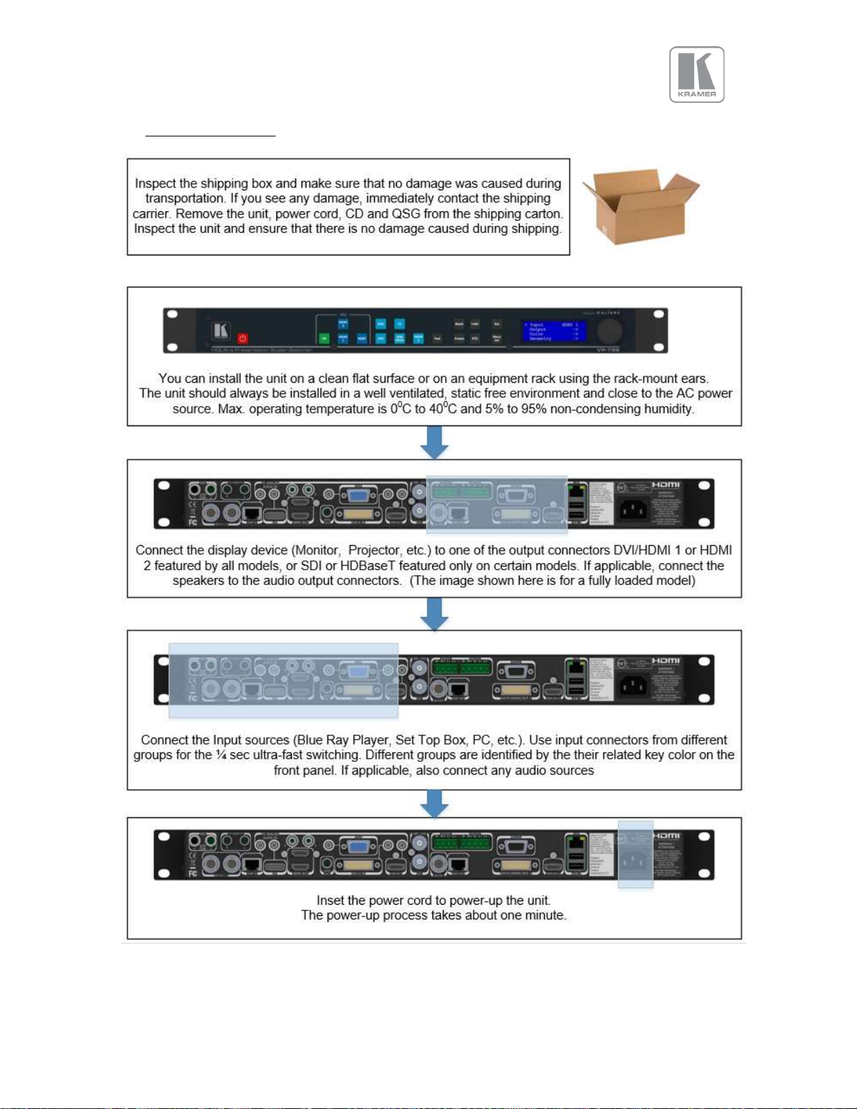
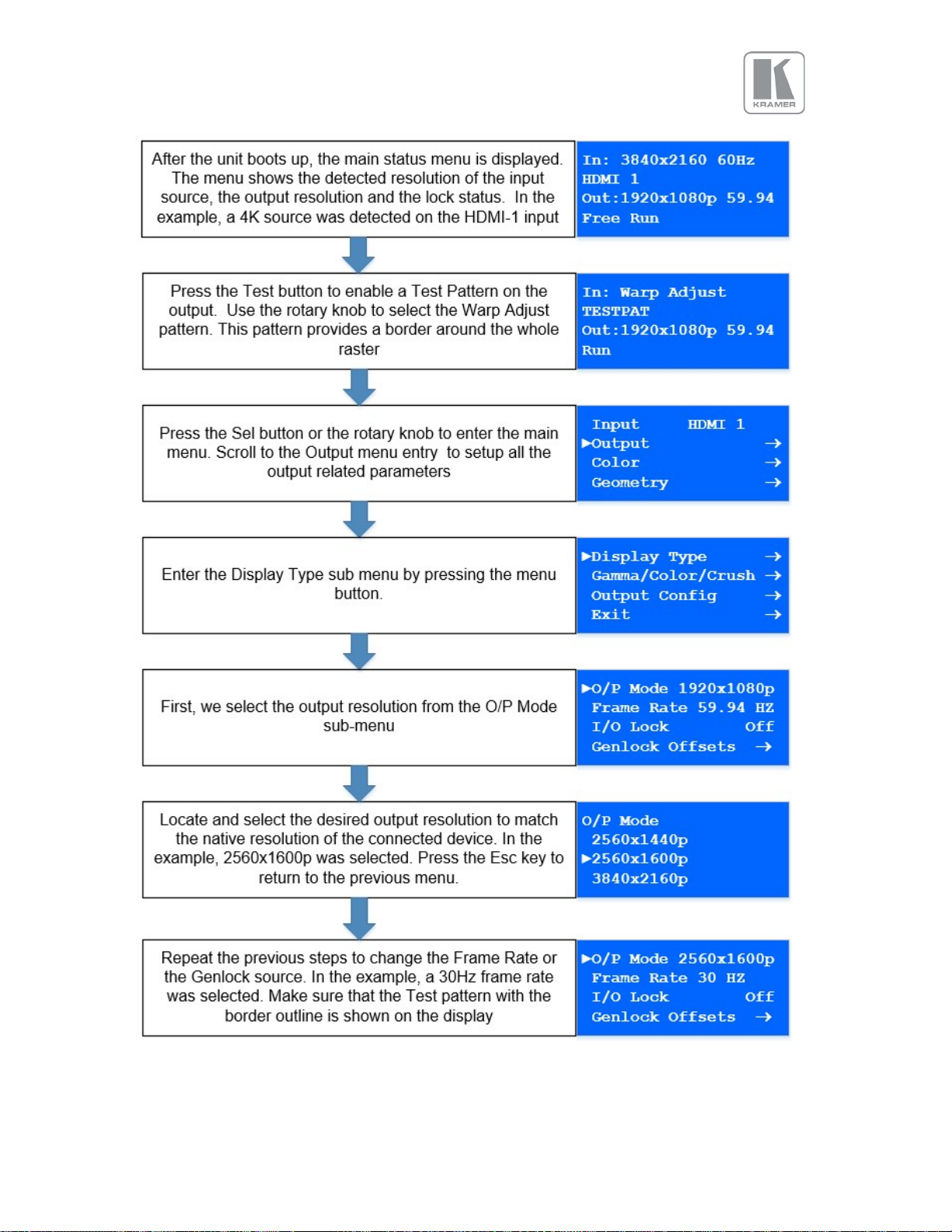
2. Basic Switcher Set-Up
© KRAMER ELECTRONICS LTD. Issue 1-13 July 28, 2016
8
© KRAMER ELECTRONICS LTD. Issue 1-13 July 28, 2016
9
© KRAMER ELECTRONICS LTD. Issue 1-13 July 28, 2016
10
Front Panel Shortcuts:
Standby + Esc
3. System Description
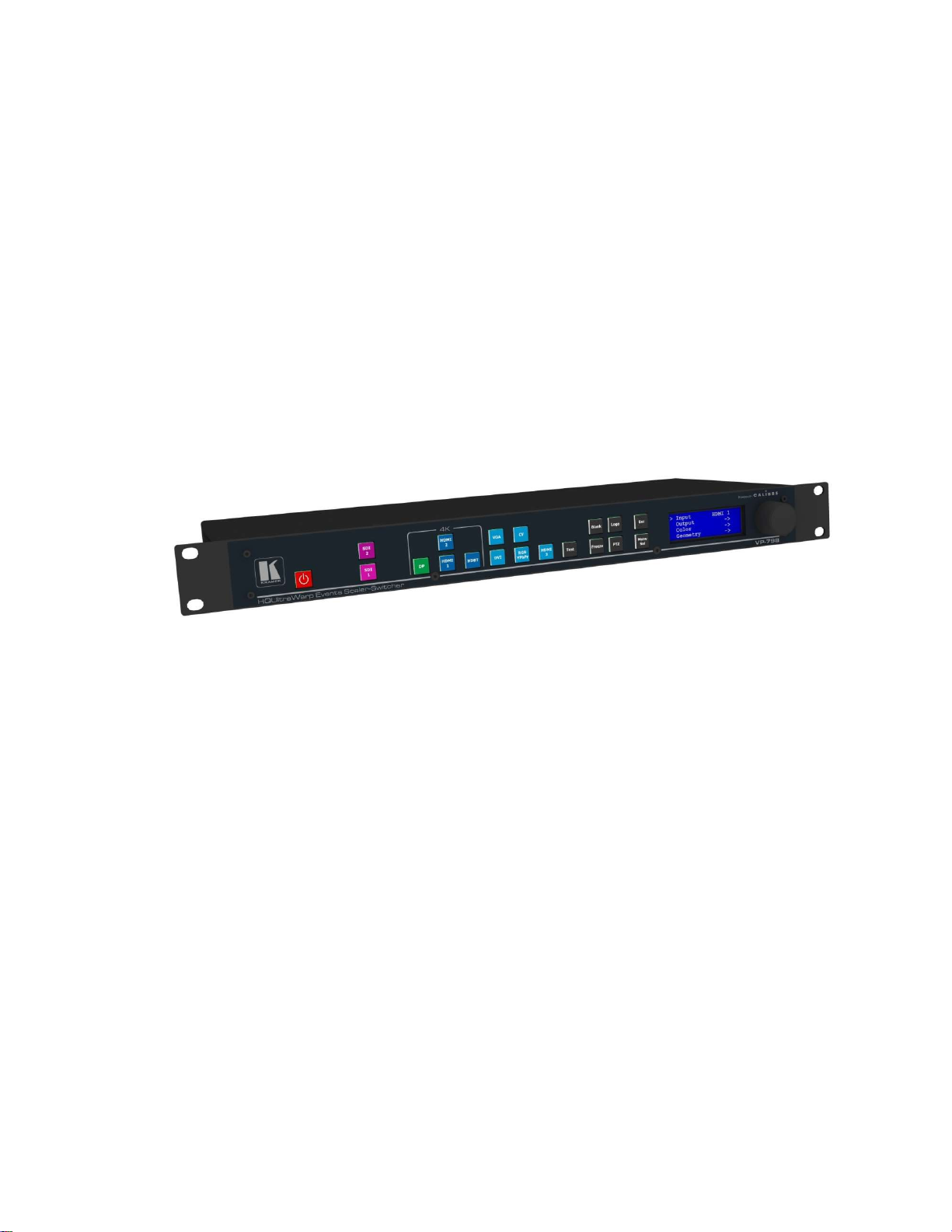
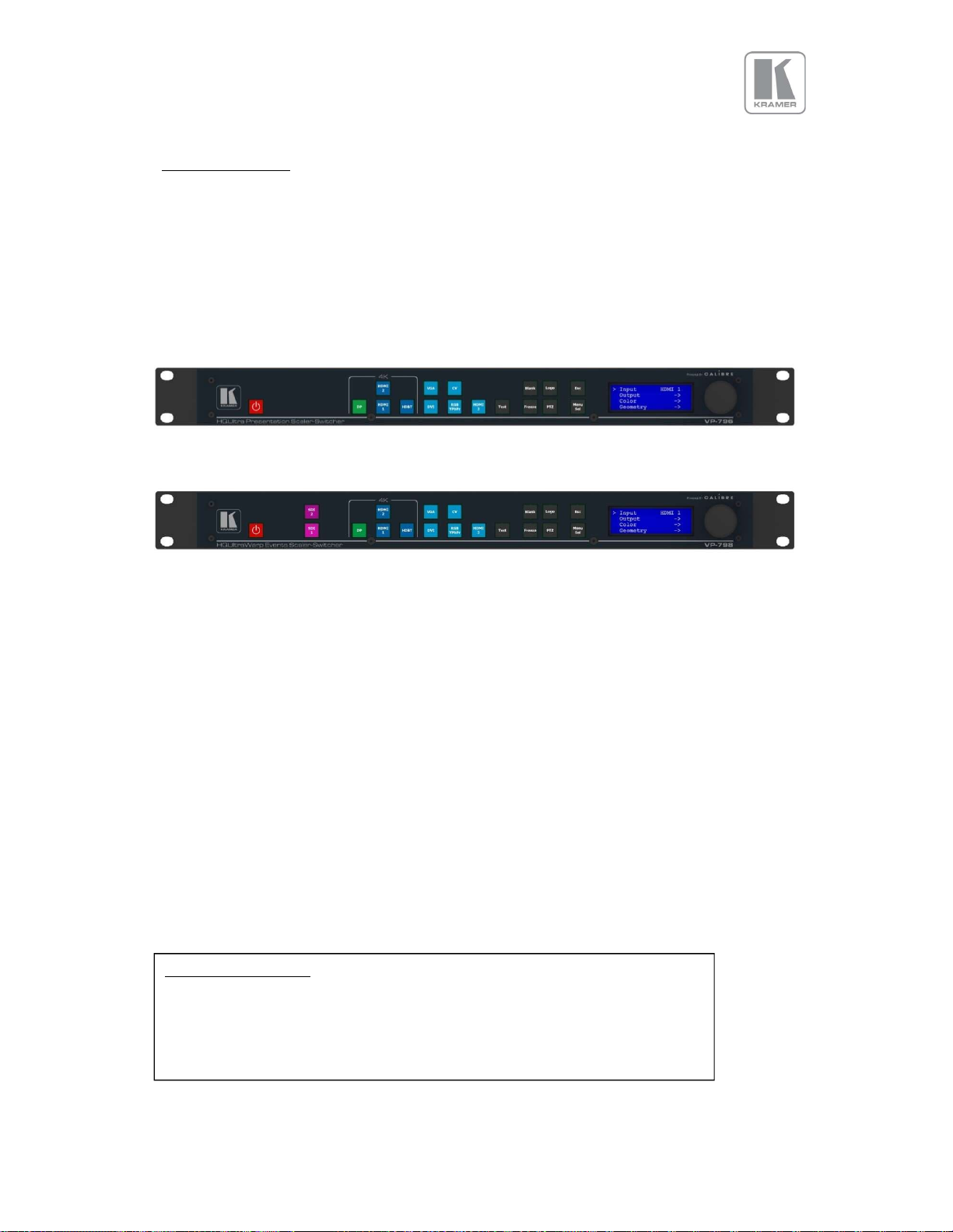
3.1 Front Panel Layout
The front panel includes several buttons allowing the user to select between the different inputs and
to perform other functions, a jog wheel and an LCD screen. From the front panel you can navigate the
menus, select the an input and direct access to key functions. The front panel layout is similar
between the different models except for the SDI, HDBT selection keys. Only models featuring these
inputs included these buttons.
VP-796 / VP-796A
VP-797 / VP-797A / VP-798 / VP-798A
1 2 3 4 5 6 7
1 – Standby key: By pressing the Standby key, the unit is put into standby mode. This is indicated by a
“STANDBY” message on the LCD with the back light turned off. When the unit starts up, the red
Standby key flashes. Once the unit is operational, the Standby key is solid red.
2 – Input channel selection keys: All input channels can be directly selected. The active channel key is
illuminated.
3 – Test Pattern key: Directly activates a Test Pattern. Use the jog wheel to scroll through the
available test patterns.
4 – Direct function keys: Four functions can be directly accessed by pressing their assigned key:
Freeze (stop/resume live video), PTZ (activate/deactivate Pan Tilt Zoom), Logo (show/skip a
predefined logo), Blank (blank the output screen/resume live video).
5 – Menu navigational keys: When the Menu/Sel key acts as an Enter or Select key for menu
changes. A jog wheel is used for menu navigation and changing values. To exit the menu or any
submenu press the Esc key or navigate to the Exit item and press the Menu/Sel key or press the jog
wheel.
6 – Front Panel LCD: Displays the Menus on a 4-line display
7 – Jog wheel: The wheel is used for navigating through the menu system and making value changes.
The jog wheel has a push function the creates the same effect as pushing the Menu/Sel key.
Keypad unlock: Esc + Menu/Sel
Mode reset: Esc + CV
Factory reset: Esc + YPbPr (in live operation or at power up)
Set output mode to 720p: Esc + VGA
Firmware version:
( press the menu button to exit )
© KRAMER ELECTRONICS LTD. Issue 1-13 July 28, 2016
11
Model
Dedicated Genlock
3.2 Input Video Connector Overview
VP-796
VP-796A
2x 3G-SDI/HD
via BNC
Display Port
via DP connector
2x HDMI (UHD,4K)
via HDMI connector
HDBaseT
via RJ45 connector
DVI & analogue (RGB/RGB/YPbPr)
via DVI-U
VGA analogue via 15HDD
Composite Video
via BNC
HDMI (HD)
Via HDMI connector
VP-797
VP-797A
VP-798
VP-798A
12
© KRAMER ELECTRONICS LTD. Issue 1-13 July 28, 2016
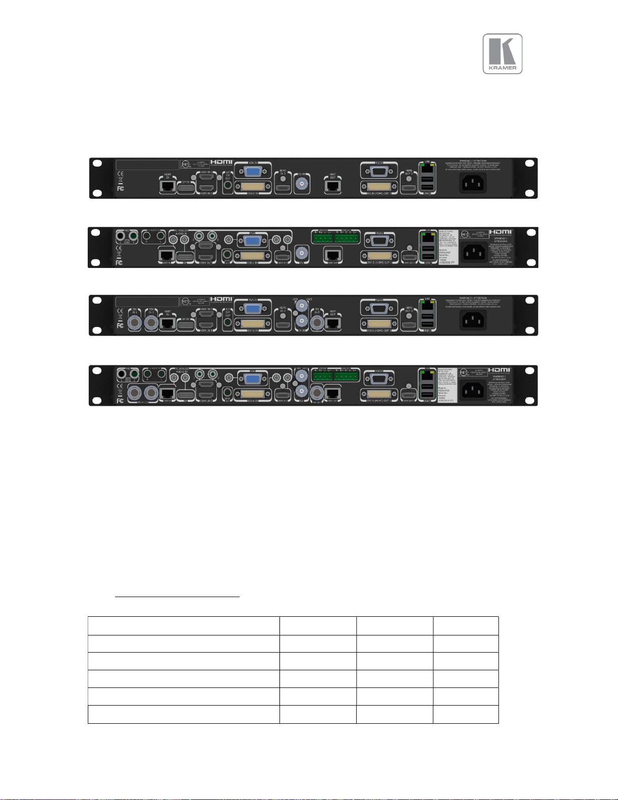
3.3 Rear Panel Layout
The rear panel features all input and output connectors, communication ports and the power supply
connector.
VP-796
VP-796A
VP-797 / VP-798
VP-797A / VP-798A
1 2 3 4 5 6/ 7 8 9/10 11 12 13/ 14 15 16 17
1 - 2x SD/HD-SDI/3G-SDI input 2 - HDBaseT (UHD/4k) input
3 - Display Port (UHD/4k) input 4 - 2x HDMI-1 & 2 (UHD/4k) input
5 - S/PDIF output 6 - VGA Input
7 - DVI-U (DVI-D and YPbPr through a cable adapter) 8 - 1x HDMI-3 (HD) input
9 - Composite Video 2 (BNC) 10 - Genlock input (BNC)
11 - 3G-SDI output 12 - HDBT (UHD/4k) output
13 - RS232 port 14 - DVI/HDMI1 (HD) output and
15 - HDMI2 (UHD/4k) output 16 - TCP/IP and 2x USB
17 - Power supply connector
3.4 Output Connector Overview
Model VP-796 VP-797 VP-798
1x 3G-SDI/HD via BNC
1x HDMI (UHD,4K) via HDMI connector
HDBaseT via RJ45 connector
DVI-D/HDMI via DVI-U
Audio Connectors
VP-796A
VP-797A
VP-798A
13
© KRAMER ELECTRONICS LTD. Issue 1-13 July 28, 2016

3.5 Product Specification
This section provides technical specification for all models. The following topics are discussed:
Power Supply Requirements
Input Specifications
Output Specifications
Supported Formats
Communication Specifications
3.5.1 Power Supply Requirement
100V-264VAC 50/60Hz connected via a standard IEC connector located on the rear panel.
3.5.2 Input Specifications
3.5.2.1 Video Inputs
Composite via BNC connector
Signal formats Composite (CVBS)
Standards NTSC, PAL, SECAM
Composite (CVBS) input level 1V p-p nominal incl. sync
Input Impedance 75 Ohms
3.5.2.2 Component Video Inputs
Via DVI-U connector and appropriate adapter cable
YPbPr (YUV), YPbPrS and RGsB component video, menu selectable.
Signal formats 484i (480i) and 576i (SD), 480p, 576p (ED), 720p, 1080i at 50, 59.94 and 60Hz
and 1080p at 23.98, 24, 25, 29.97 and 30Hz.
Please note this input does not support Computer SVGA signals which should be connected via
the Computer SVGA input, The SVGA input supports the separate H & V syncs.
3.5.2.3 3G-SDI Input
Format: SD-SDI, HD-SDI and 3G-SDI YCbCr 4:2:2 serial digital component video
Input impedance: 75 ohms.
SMPTE 292M, SMPTE 259M-C and SMPTE 424M compliant, accepts 484i, 576i, 720, 1080i and
1080p single link formats at 270Mb, 1.485Gb or 2.97Gb rates.
3.5.2.4 Computer (SVGA) Inputs VESA formats
Signal formats: DOS, VGA – WUXGA up to 165MHz pixel clock
RGB video level: 0.7V - 1.0V
RGB input impedance: 75 Ohms
Sync format : Separate H & V sync at TTL/5V levels.
3.5.2.5 HDMI & DVI Inputs
HDMI with or without HDCP, 36-bit video compatible.
DVI-D input with or without HDCP
Signal formats - video
SD: 625i (576i) and 525i (480i) in double-rate formats;
ED: 480p, 576p;
© KRAMER ELECTRONICS LTD. Issue 1-13 July 28, 2016
14

HD: 1280x720p, 1920x1080i, 1920x1080psf; 1920x1080p 23.97, 24, 25, 29.94, 30, 50, 59.94 &
60Hz; 2048x1080p 23.97, 24, 25, 29.94, 30, 50, 59.94 & 60Hz.
HDMI 1 and HDMI 2 support: 4K signals: 3840x2160p & 4096x2160p 23.97, 24, 25, 29.94, 30,
50, 59.94 & 60Hz (50, 59.94 & 60Hz supported in YUV 4:2:0 colour space format),
Signal formats – computer
Common VESA graphics formats from VGA to 4k up to 297 MHz (HDMI 1 and HDMI 2) and 225
MHz (HDMI 3) pixel clock
3.5.2.6 DP Input
Display Port without HDCP, 36-bit video compatible.
Signal formats as HDMI 1 and HDMI 2.
3.5.2.7 HDBT Input
Uncompressed HD video over RJ45 connector and max.100m CAT5e cable (or better)
CAT5e/CAT6 for 100m and signals with less than 225MHz Pixel Clock
CAT6a/CAT7 for 100m and signals up to 297MHz Pixel Clock
Signal formats as HDMI 1 and HDMI 2.
HDMI-1 and HDMI-2 and HDBT inputs support RGB and YUV 4:2:0 colour space formats.
Signals with YUV 4:4:4 and YUV 4:2:2 colour space formats need to be connected to the HDMI3 or
DVI input.
Graphics formats with odd numbered horizontal active pixels, e.g. 1365x768 are not supported.
3.5.3 Output Specifications
All output channels are active simultaneously, provided that the input signal is not HDCP encrypted. All
units include an HDMI, and a DVI-U connectors for DVI/HDMI connectivity. Some models feature a BNC
connector for 3G-SDI signals and an RJ-45 connector supporting HDBaseT capability. The DVI-D
connector supports HDMI with 36-bit video and audio formats when connected to a suitable HDMI
receiver. The colour depth of the HDMI signal is determined by a menu selection and the capabilities of
the monitor.
Interlaced outputs are only supported on models with 3G-SDI output.
3.5.3.1 3G-SDI Output
Format: SD-SDI, HD-SDI and 3G-SDI YCbCr 4:2:2 serial digital component video
Input impedance: 75 ohms.
SMPTE 292M, SMPTE 259M-C and SMPTE 424M compliant, accepts 484i, 576i, 720, 1080i and
1080p single link formats at 270Mb, 1.485Gb or 2.97Gb rates.
3.5.3.2 HDMI & DVI Outputs
HDMI with or without HDCP, 36-bit video compatible.
DVI-D input with or without HDCP
Signal formats - video
SD: 625i (576i) and 525i (480i) in double-rate formats;
ED: 480p, 576p;
15
© KRAMER ELECTRONICS LTD. Issue 1-13 July 28, 2016
Output Channel
Output Format
HDMI
PCM up to 8ch, up to 24Bit, up to 192kHz sampling rate
SDI PCM up to 8ch, up to 24Bit,
48kHz sampling rate
SPDIF
PCM up to 2ch, up to 24Bit, up to 96kHz sampling rate
HD: 1280x720p, 1920x1080i, 1920x1080psf; 1920x1080p 23.97, 24, 25, 29.94, 30, 50, 59.94 &
60Hz; 2048x1080p 23.97, 24, 25, 29.94, 30, 50, 59.94 & 60Hz.
HDMI 1 and HDMI 2 support: 4K signals: 3840x2160p & 4096x2160p 23.97, 24, 25, 29.94, 30,
50, 59.94 & 60Hz (50, 59.94 & 60Hz supported in YUV 4:2:0 colour space format),
Signal formats – computer
Common VESA graphics formats from VGA to 4k up to 297 MHz (HDMI 1 and HDMI 2) and 225
MHz (HDMI 3) pixel clock
3.5.3.3 HDBT Output
Uncompressed HD video over RJ45 connector and max.100m CAT5e cable (or better)
CAT5e/CAT6 for 100m and signals with less than 225MHz Pixel Clock
CAT6a/CAT7 for 100m and signals up to 297MHz Pixel Clock
Signal formats as HDMI 1 and HDMI 2.
3.5.3.4 HDCP Output encryption
When the input signal is HDCP encrypted, the DVI-D, HDMI and HDBaseT outputs will also be
encrypted and the 3G-SDI output will be disabled. If the display device does not support
HDCP, the output will be black and a message indicating that the presence of an HDCP signal
will be shown on the screen.
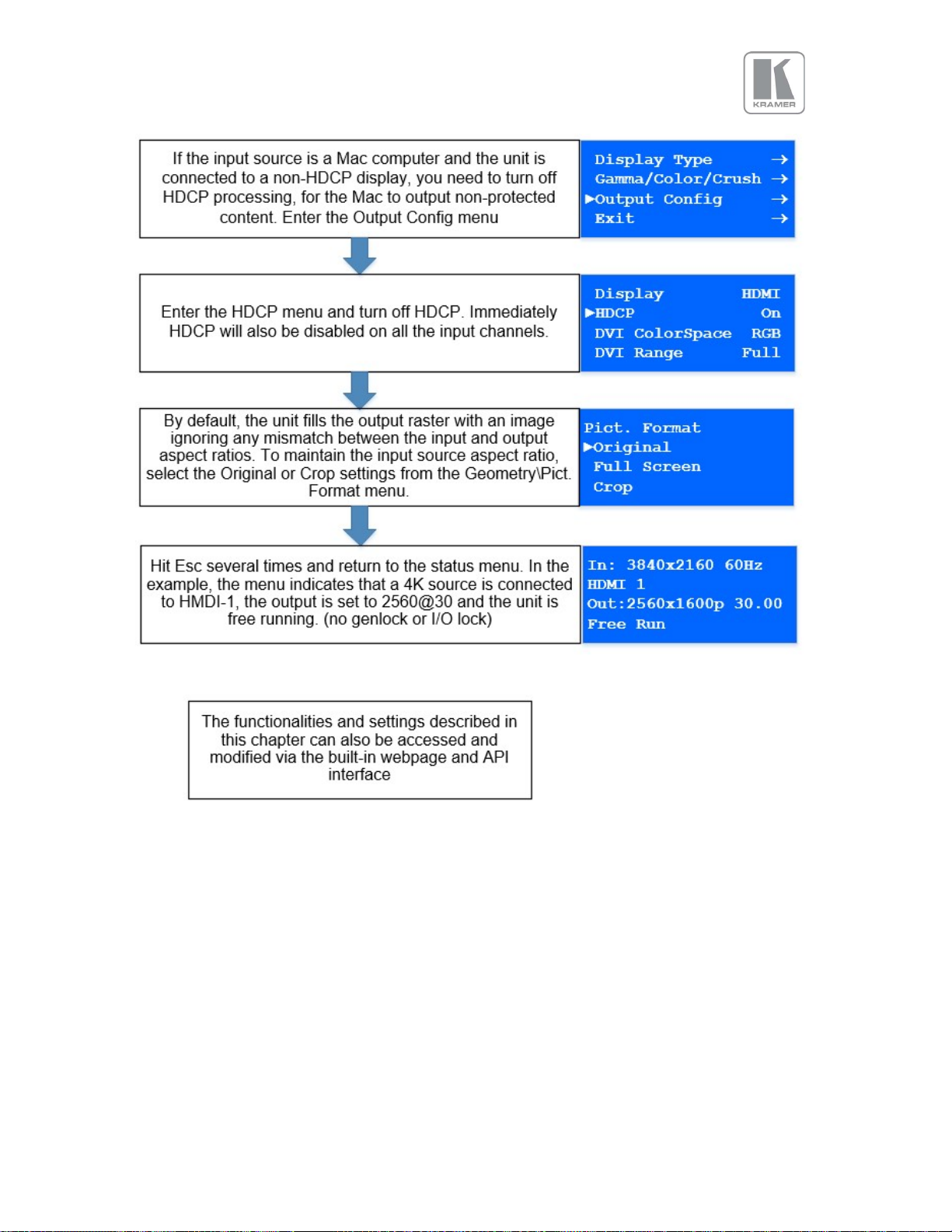
The user can turn off the unit’s HDCP compliance to allow non-encrypted content to pass
through the unit. This is an important feature specially when using a MAC computer as the
source. The MAC will encrypt its output signal if a compliant device is seen attached to its
output regardless of the copy protection requirements of the content. By turning off HDCP,
the MAC will see a non-compliant device and therefore will not encrypt its output. When
HDCP compliance is turned off, encrypted sources will not be displayed.
3.5.3.5 Audio Output
Audio embedded in HDMI and SDI video streams is passed through the system and re-embedded into
the HDMI and SDI output signals.
Also, the unit features a S/PDIF coaxial digital audio output connector for monitoring audio of the HDMI
and SDI channel.
When HDMI is selected as the input channel, the HDMI EDID is read by a video source such as a Blu- Ray
Player. The unit allows the source to provide the formats shown under output formats for HDMI in the
below table. All formats are re-embedded into the HDMI output data stream, those which are not
allowed on the SDI or SPDIF output are muted on the individual channels.
(incl. 32kHz,44.1kHz,48kHz,96kHz,192kHz)
(incl. 32kHz,44.1kHz,48kHz,96kHz)
© KRAMER ELECTRONICS LTD. Issue 1-13 July 28, 2016
16

3.5.4 Analog Audio
Units supporting audio include up-to 8 analog stereo Inputs, two microphone Inputs with phantom
power and an audio mixer.
Analog stereo signals are connected to the unit via 3.5 mm jack sockets, except for the CV input that is
associated with two RCA connectors. Using the audio menu, any video input can be link with any
audio input and mixed with the mic inputs.
Audio models also include stereo audio power amplifier supporting 15W RMS loudspeaker per output
and separate stereo balanced line level audio outputs for external amplifier systems. The analog
stereo outputs are available on two phoenix connectors.
© KRAMER ELECTRONICS LTD. Issue 1-13 July 28, 2016
17
CVT 1.30MA/VESA
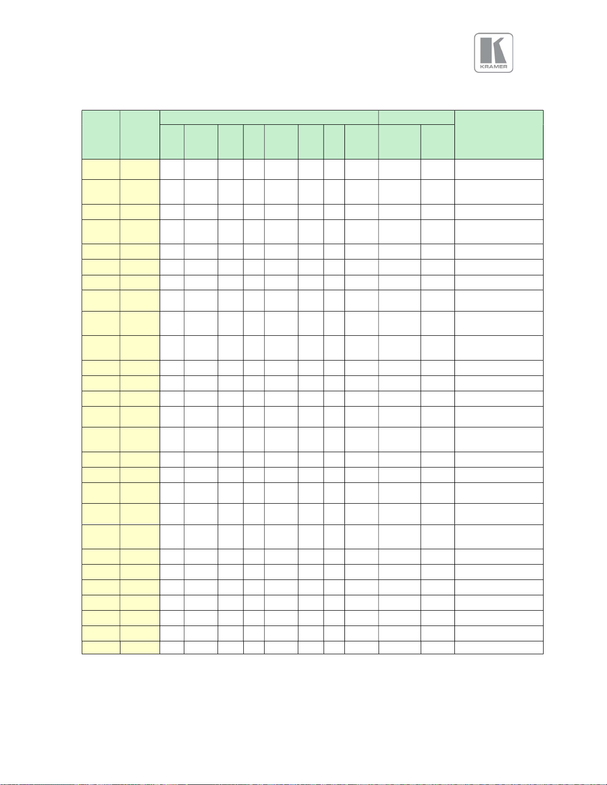
3.5.5 Supported formats
Horiz.
Active
Pixels
640 480
720 480i
720 480p
720 576i
720 576p
800 600
1024 768
1280 720
1280 768
1280 800
1280 1024
1360 768
1366 768
1440 900
1400 1050
1600 1200
1680 1050
1920 1080i
1920 1080p
1920 1200
2048 1080
2048 1200
2560 1080
2560 1440
2560 1600
3840 2160
4096 2160
Vert.
Active
Lines
60 59.94 50 30 29.97 25 24 23.98
Vertical Refresh Rate (Hz) Outputs
DVI
HDMI
HDBT
3GSDI
EIA/CEA-861-B Format
EIA/CEA-861-B Format
EIA/CEA-861-B Format
001M9/VESA DMT
001MA/VESA DMT
001M3/VESA DMT
VESA CVT 002MA
EIA/CEA-861-B Format
EIA/CEA-861-B Format
VESA CVT 002MA-
EIA/CEA-861-F VIC=86
VESA CVT 004M-R
VESA CVT 004M-R
EIA/CEA-861-F VIC=93
EIA/CEA-861-F VIC=98
Specification
VESA DMT
6 (NTSC)
17 (PAL)
VESA DMT
VESA DMT
4
VESA CVT
VESA CVT
VESA DMT
VESA DMT
proprietary
DMT
VESA CVT
VESA DMT
5
5
R/VESA DMT
proprietary
proprietary
18
© KRAMER ELECTRONICS LTD. Issue 1-13 July 28, 2016
 Loading...