

Page 1

© KRAMER ELECTRONICS LTD. Issue 1.10 16
th
of December 2015 1
VP-796
Operating Instructions
Page 2

© KRAMER ELECTRONICS LTD. Issue 1.10 16
th
of December 2015 2
This manual explains how to operate your VP-796 Presentation Scaler-Switcher.
If you have any queries relating to this or any other product supplied by Kramer please visit our
web site www.kramerelectronics.com.
All trademarks acknowledged
Kramer operates a policy of continued product improvement, therefore specifications are subject to
change without notice as products are updated or revised.
E&OE.
Page 3

© KRAMER ELECTRONICS LTD. Issue 1.10 16
th
of December 2015 3
Contents
SAFETY WARNING 5
INTRODUCTION 6
1.1. General Introduction 6
1.2. Packing List 7
QUICK SET-UP FLOW CHART 8
2.1. Basic Switcher Set-Up 8
VP SYSTEM DESCRIPTION 9
3.1. Product Overview 10
3.2. Product Specification 10
3.2.1. Power Supply Requirement 10
3.2.2. Video Inputs 10
3.2.3. Component Video Inputs 10
3.2.4. Computer (SVGA) Inputs VESA formats 11
3.2.5. HDMI & DVI Inputs 11
3.2.6. DP Input 11
3.2.7. HDBT Input 11
3.2.8. Audio Output 12
3.2.9. Display Output 13
UNIT CONTROL 16
4.1. LCD Panel Control 16
4.2. Web Browser Control 19
4.3. Introduction 24
4.4. Main Menu 26
4.5. Input 26
4.6. Output 26
4.6.1. Display Type 26
4.6.2. Gamm/Color/Crush 28
4.6.3. Output Config 29
4.7. Colour 29
4.7.1. Black-Level Offset 29
4.7.2. Black-Level 29
4.7.3. Contrast 30
4.7.4. Saturation 30
4.7.5. Hue 30
4.7.6. RGB values 30
4.7.7. Colour Temp 30
4.7.8. Input Gamma 30
4.8. Geometry 30
4.8.1. Picture Format 30
4.8.2. Overscan 31
4.8.3. Pan Tilt Zoom 31
4.9. Enhancement 32
4.9.1. Sharpness 32
4.9.2. Detail 32
4.10. System 33
4.10.1. User 33
4.10.2. Names/Profiles 33
4.10.3. Input Config 33
4.10.4. Menu Settings 35
4.10.5. Network Settings 35
4.10.6. Security Settings 36
4.10.7. Factory Defaults 36
4.11. Status 36
FIRMWARE UPDATE 37
5.1. Introduction 37
5.2. Updating Firmware 37
ENVIRONMENTAL AND EMC 38
6.1. Recommended Operating Conditions 38
Page 4

© KRAMER ELECTRONICS LTD. Issue 1.10 16
th
of December 2015 4
6.2. Storage 38
6.3. CE and FCC Compliance 38
6.4. PAT Testing 38
Page 5

© KRAMER ELECTRONICS LTD. Issue 1.10 16
th
of December 2015 5
SAFETY WARNING
1. THERE ARE NO USER SERVICEABLE PARTS WITHIN THE UNIT. REMOVAL OF THE TOP COVER
WILL EXPOSE DANGEROUS VOLTAGES. DO NOT OPERATE THE UNIT WITHOUT THE TOP COVER
INSTALLED.
2. ENSURE THAT ALL ELECTRICAL CONNECTIONS (INCLUDING THE MAINS PLUG AND ANY
EXTENSION LEADS) ARE PROPERLY MADE AND COMPLY WITH ELECTRICAL SAFETY
REGULATIONS.
3. ENSURE THAT THE INTEGRITY OF THE EQUIPMENT ISOLATION BARRIER IS MAINTAINED WHEN
CONNECTING TO OTHER EQUIPMENT. THIS MEANS THAT ONLY LOW VOLTAGE ISOLATED
CIRCUITS MAY BE CONNECTED TO THE SIGNAL INPUTS AND OUTPUTS. IF ANY DOUBT EXISTS
CONSULT QUALIFIED SERVICE PERSONNEL.
4. TO PREVENT SHOCK OR FIRE HAZARD DO NOT EXPOSE THIS EQUIPMENT TO RAIN OR
MOISTURE. IF SUCH EXPOSURE OCCURS, REMOVE THE PLUG FROM THE MAINS OUTLET AND
HAVE THE EXPOSED UNIT CHECKED BY QUALIFIED SERVICE PERSONNEL.
5. DO NOT CONTINUE TO OPERATE THE EQUIPMENT IF YOU HAVE ANY DOUBT ABOUT IT
WORKING NORMALLY, OR IF IT IS DAMAGED IN ANY WAY. WITHDRAW THE MAINS PLUG FROM
THE MAINS OUTLET AND CONSULT QUALIFIED SERVICE PERSONNEL.
6. DO NOT REMOVE ANY FIXED COVERS UNLESS YOU ARE QUALIFIED TO DO SO AND EVEN THEN
WITHDRAW THE MAINS PLUG FROM THE MAINS OUTLET BEFORE YOU START.
7. THIS EQUIPMENT CONTAINS NO USER SERVICEABLE PARTS. REFER ALL SERVICING AND
MAINTENANCE TO QUALIFIED SERVICE PERSONNEL.
8. TO AVOID EXPLOSION, DO NOT OPERATE THIS EQUIPMENT IN AN EXPLOSIVE ATMOSPHERE
Page 6

© KRAMER ELECTRONICS LTD. Issue 1.10 16
th
of December 2015 6
INTRODUCTION
1.1.
General Introduction
VP-796 features excellent image processing algorithms for the very best scaling, and market leading
HD & SD per-pixel multiple Iow-angle motion-adaptive de-interlacing and automatic film 3:2 and 2:2
pull-down correction, significantly outperforming the capabilities of benchmark competitor products.
The unit can be operated as a seamless switcher with extremely fast switching transitions.
VP-796 uses a very flexible high performance video input front end including true component video
support in analogue YPbPr and RGBS formats as well as composite (CVBS) inputs. A very high
performance video decoder is utilised with 4x oversampling and 3D Y/C separation for outstanding
video image clarity.
HDMI, DVI, HDBT and Display Port video with HDCP encryption is also supported, as are computer
graphics inputs in SVGA analogue and HDMI/DVI digital formats.
The output format can be set to I/O Lock mode where it locks the output frame rate to the input frame
rate dynamically without frame rate conversion so as to reduce system latency, or it can be set to a
fixed output frame rate, e.g. for driving basic screens which are not 50Hz-compatible. The output format
can also be set to lock to an externally provided synchronization signal on various models (see model
matrix).
Outputs are available in HDMI/DVI digital and HDBaseT formats on various models which are useable
simultaneously.
Please note that if an HDCP encrypted signal is connected to the DP, HDMI or DVI input, the HDMI and
DVI output signals will be similarly HDCP encrypted. HDCP capability can be switched off by the units,
so that a source may be forced to output non content protected material unencrypted.
VP-796 supports Pan, Tilt and Zoom to select a ‘region of interest’ portion of the input image, fill the
screen and pan/tilt within it.
System control is via a menu system through the inbuilt TCP/IP web server or via the built in LCD panel
and jog dial. Additionally a free API manual is published on our website of the LAN remote control port.
Page 7

© KRAMER ELECTRONICS LTD. Issue 1.10 16
th
of December 2015 7
1.2.
Packing List
VP-796 is supplied with the following:
1) 3 pin plug IEC mains cable
2) CD (w/ documentation)
Page 8
© KRAMER ELECTRONICS LTD. Issue 1.10 16
th
of December 2015 8
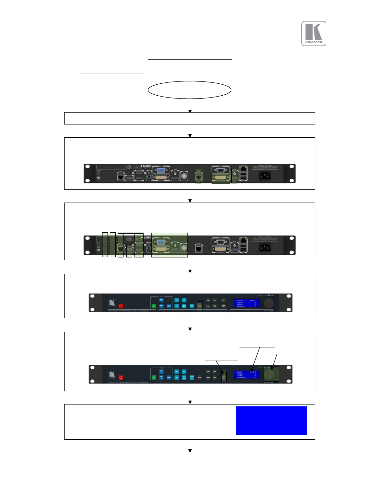
QUICK SET-UP FLOW CHART
2.1.
Basic Switcher Set-Up
Connect Power
Connect Sources (Blue Ray Player, Set Top Box, PC, etc.)
Use input connectors from different groups for ultra-fast switching, groups are identified by
input channel keys with identical color.
Press the Test button so the unit displays an image regardless of the state of the sources
connected.
Press the Menu/Select button to activate the menu system. Scroll through the menu system
with the jog wheel. Turn the wheel to the left to climb down the menu system, and to the
right to climb up the menu. The jog wheel has a push function. Pushing the jog wheel has
the same effect as pressing the Menu/Select button.
Scroll to the menu item Output with the jog wheel. Input TESTPAT
The menu will look like this with the Output menu item marked >Output >
by an arrow. Color >
Geometry >
Connect the display device (Monitor, LED Wall, Projector, etc.)
to one of the output connectors DVI/HDMI 1, HDMI 2 or HDBaseT.
Start
Page 9
© KRAMER ELECTRONICS LTD. Issue 1.10 16
th
of December 2015 9
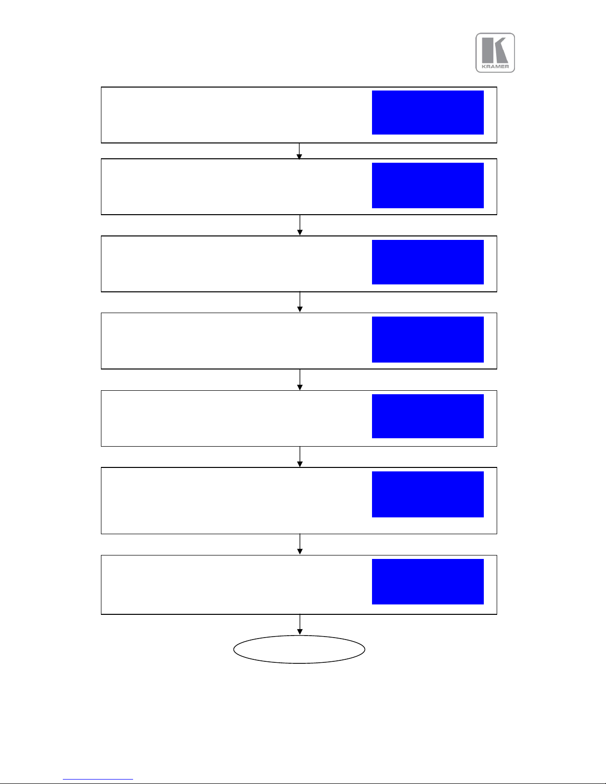
The Display Type sub menu allows changing the default >O/P Mode 1920x1080p
output mode of 1080p at 60Hz. Press the menu button and a Frame Rate 60 Hz
list of output modes is shown. I/O Lock Off
Frame Rates >
This is a list box. The currently selected mode and the nearest O/P Mode
neighbors are shown. Use the jog wheel to scroll to the desired 1920x1080i
output mode and press the menu button to select it. Let us >1920x1080p
assume the unit was set to UHD resolution. 2048x1080p
The Display Type menu will show up again and the newly >O/P Mode 3840x2160p
chosen mode is active. Frame Rate 60 Hz
I/O Lock Off
Frame Rates >
Press the Esc (Escape) button on the keyboard three times to In: SMPTE
successively get the menu tree up again. Finally the following TESTPAT
status screen will be displayed. Out:3840x2160p 60Hz
Now press an input channel key on the keyboard to switch to Free Run
a connected source, e.g. HDMI 1.
Let us assume the input is 1080p 59.94Hz from e.g. a BD In: 1920x1080p 59Hz
player. The status menu changes to the following screen. HDMI 1
An image should be seen on the display connected. Out:3840x2160p 60Hz
Free Run
Enter the Display Type sub menu by pressing the menu button. >Display Type >
(Note: Since the first item of a sub menu is selected when Gamma/Color/Crush >
first entered the jog wheel does not need to be used to select Output Config >
the Display Type menu item.) Exit >
Press the menu button to enter the Output menu. >Display Type >
The menu will now look like this. Gamma/Color/Crush >
Output Config >
Exit >
Finished
Page 10
© KRAMER ELECTRONICS LTD. Issue 1.10 16
th
of December 2015 10
VP SYSTEM DESCRIPTION
3.1.
Product Overview
The unit designed to accept the following input signals:
Model
VP-796
VP-797
VP-798
2x 3G-SDI/HD-SDI/SDI
(Serial Digital Interface) via BNC
Display Port
via DP connector
2x HDMI (4k)
via HDMI connector
HDBaseT
Via RJ45 connector
DVI via DVI-U
(supporting a digital and a YPbPr input)
VGA analogue via 15HDD
Composite Video
via BNC
HDMI (1080p deep color)
via HDMI connector
3.2.
Product Specification
This section provides technical details for all possible inputs.
3.2.1.
Power Supply Requirement
100V-264VAC 50/60Hz connected via a standard IEC connector located on the rear panel.
3.2.2.
Video Inputs
Composite via BNC connector
Signal formats Composite (CVBS)
Standards NTSC, PAL, SECAM
Composite (CVBS) input level 1V p-p nominal incl. sync
Input Impedance 75 Ohms
3.2.3.
Component Video Inputs
Via DVI-U connector and appropriate adapter cable
YPbPr (YUV), YPbPrS and RGsB component video, menu selectable.
Signal formats 484i (480i) and 576i (SD), 480p, 576p (ED), 720p, 1080i at 50, 59.94 and 60Hz and
1080p at 23.98, 24, 25, 29.97 and 30Hz.
Please note this input does not support Computer SVGA signals which should be connected via the
Computer SVGA input, The SVGA input supports the separate H & V syncs.
Page 11

© KRAMER ELECTRONICS LTD. Issue 1.10 16
th
of December 2015 11
3.2.4.
Computer (SVGA) Inputs VESA formats
Signal formats: DOS, VGA – WUXGA up to 165MHz pixel clock
RGB video level 0.7V - 1.0V
RGB input impedance 75 Ohms
Sync format Separate H & V sync at TTL/5V levels.
3.2.5.
HDMI & DVI Inputs
HDMI with or without HDCP, 36-bit video compatible.
DVI-D input with or without HDCP
Signal formats - video
SD: 625i (576i) and 525i (480i) in double-rate formats; ED: 480p, 576p; HD: 1280x720p, 1920x1080i,
1920x1080psf; 1920x1080p 23.97, 24, 25, 29.94, 30, 50, 59.94 & 60Hz; 2048x1080p 23.97, 24, 25,
29.94, 30, 50, 59.94 & 60Hz.
The 4k capable HDMI 1 and HDMI 2 inputs also support: 3840x2160p & 4096x2160p 23.97, 24, 25,
29.94, 30, 50, 59.94 & 60Hz (50, 59.94 & 60Hz supported in YUV 4:2:0 colour space format),
Signal formats – computer
Common VESA graphics formats from VGA to 4k up to 297 MHz (HDMI 1 and HDMI 2) and 225 MHz
(HDMI 3) pixel clock
Note: As of now HDMI1/2 and HDBT inputs support RGB and YUV 4:2:0 colour space formats. Signals
with YUV 4:4:4 and YUV 4:2:2 colour space formats need to be connected to the HDMI3 or DVI input.
Note: Graphics formats with odd numbered horizontal active pixels, e.g. 1365x768 are currently not
supported.
3.2.6.
DP Input
Display Port without HDCP, 36-bit video compatible.
Signal formats as HDMI 1 and HDMI 2.
3.2.7.
HDBT Input
Uncompressed HD video over RJ45 connector and max.100m CAT5e cable (or better)
CAT5e/CAT6 for 100m and signals with less than 225MHz Pixel Clock
CAT6a/CAT7 for 100m and signals up to 297MHz Pixel Clock
Signal formats as HDMI 1 and HDMI 2.
Page 12

© KRAMER ELECTRONICS LTD. Issue 1.10 16
th
of December 2015 12
3.2.8.
Audio Output
Audio is embedded in HDMI video streams and brought into the unit through the respective input
channels. The audio is passed through the system and re-embedded into the HDMI output signals.
Also, the unit features a S/PDIF coaxial digital audio output connector for monitoring audio of the HDMI
channel.
When HDMI is selected as the input channel the HDMI EDID is read by a video source such as a Blue
Ray Player. The unit allows the source to provide the formats shown under output formats for HDMI in
the below table.
All formats are re-embedded into the HDMI output data stream, those which are not allowed on SPDIF
output are muted on the individual channels.
Output Channel
Output Format
HDMI
PCM up to 8ch, up to 24Bit, up to 192kHz sampling rate
(incl. 32kHz,44.1kHz,48kHz,96kHz,192kHz)
Dolby Digital (AC3) up to 5.1 channels, up to 640kBit/sec bit stream rate
MPEG2 up to 8ch, up to 112kBit/sec bit stream rate
DTS up to 6.1 channels, up to 1536kBit/sec bit stream rate
SPDIF
PCM up to 2ch, up to 24Bit, up to 96kHz sampling rate
(incl. 32kHz,44.1kHz,48kHz,96kHz)
Dolby Digital (AC3) up to 5.1 channels
DTS up to 6.1 channels
Page 13

© KRAMER ELECTRONICS LTD. Issue 1.10 16
th
of December 2015 13
3.2.9.
Display Output
Three output channels are provided which are useable simultaneously. That is an HDMI, a DVI-I output
connector for DVI/HDMI connectivity and an RJ45 connector for HDBaseT connectivity.
When the input signal has HDCP encryption, the DVI-D, HDMI and HDBaseT output connectors will
carry a similarly HDCP encrypted signal.
When an HDCP encrypted signal is input, but the display device does not support HDCP, the
output image will turn black and a message indicating HDCP Signal will come up to the LCD
menu screen to indicate this.
There is a DVI-D and HDMI output. Both conform to normal VESA standards for connectors and pin
outs for these signal types.
The DVI-D connector will support HDMI with 36-bit video and audio formats when connected to a
suitable HDMI receiver. The colour depth of the HDMI signal is determined by the set-up of the unit and
the capabilities of the monitor.
4096x2160 currently is supported at 23.97/24Hz/29.97/30/50. 4096x2160 at 59.94/60 is not supported.
Note: The processor’s HDCP compliance can be turned off. This is of importance particularly
when using a MAC computer as the source. A MAC will encrypt its output signal if a compliant
device is seen attached to its output regardless of copy protection requirements to the content.
By turning off the unit processor’s compliance the MAC will see a non-compliant device and
therefore will not encrypt its output. When HDCP compliance is turned off encrypted sources
will not be displayed.
Note: The DVI/HDMI1 output of HDBaseT enabled products works fine with most displays at 4k.
However, this cannot be guaranteed. There may be occasional short video drop outs which
immediately recover. The frequentness depends on the display input electrical circuitry, the
input format measurement of the display and the quality of the cable being used.
Page 14

© KRAMER ELECTRONICS LTD. Issue 1.10 16
th
of December 2015 14
The following output modes can be set up:
(HFP/VFP: horizontal/vertical front porch, HBP/VBP: horizontal/vertical front porch, HS/VS:
horizontal/vertical sync, HTot/VTot: horizontal/vertical total pixels)
Hor Pix
Ver Pix
HTot
HFP
HS
HBP
VTot
VFP
VS
VBP
Hor Freq
Ver Freq
Pix Clock
Specification
640
480
800
16
96
48
525
10 2 33
31.47
59.94
25.175
VESA DMT
640
480
800
16
96
48
629
62 2 85
31.46
50.02
25.170
proprietary
640
480
800
16
96
48
629
62 2 85
30.19
48.00
24.154
proprietary
800
600
1056
40
128
88
628 1 4
23
37.88
60.31
40.000
VESA DMT
800
600
1056
40
128
88
628 1 4
23
31.40
50.00
33.158
VESA 60 - CLK wind down
800
600
1056
40
128
88
628 1 4
23
30.14
48.00
31.832
proprietary
1024
768
1344
24
136
160
806 3 6
29
48.36
60.00
65.000
VESA DMT
1024
768
1312
40
104
144
793 3 4
18
39.63
49.98
52.000
VESA CVT 001M3
1024
768
1312
40
104
144
793 3 4
18
38.11
48.06
50.000
proprietary
1280
768
1664
64
128
192
798 3 7
20
47.78
59.87
79.500
VESA CVT 001M9/VESA DMT
1280
768
1648
56
128
184
793 3 7
15
39.59
49.93
65.250
VESA CVT001M9
1280
768
1648
56
128
184
793 3 7
15
38.06
48.00
62.730
proprietary
1280
800
1680
72
128
200
831 3 6
22
49.70
59.81
83.500
VESA CVT 001MA/VESA DMT
1280
800
1680
72
128
200
831 3 6
22
41.55
50.00
69.804
propietary
1280
800
1680
72
128
200
831 3 6
22
39.89
48.00
67.012
propietary
1280
1024
1688
48
112
248
1066 1 3
38
63.98
60.02
108.000
VESA DMT
1280
1024
1688
48
112
248
1066 1 3
38
53.32
50.02
90.000
VESA 60 - CLK wind down
1280
1024
1688
48
112
248
1066 1 3
38
51.17
48.00
86.370
proprietary
1360
768
1792
64
112
256
795 3 6
18
47.71
60.02
85.500
VESA AddDMT
1360
768
1744
56
136
192
793 3 5
17
39.56
49.89
69.000
VESA CVT 001M9
1360
768
1688
48
112
248
1066 1 3
38
51.17
48.00
86.370
proprietary
1366
768
1792
26
100
300
795 4 3
20
47.70
60.00
85.478
proprietary
1366
768
1792
26
100
300
795 4 3
20
39.75
50.00
71.232
proprietary
1400
1050
1864
88
144
232
1089 3 4
32
65.31
59.98
121.750
VESA CVT 001M3/VESA DMT
1400
1050
1864
88
144
232
1089 3 4
32
54.43
49.98
101.458
VESA 60 - CLK wind down
1400
1050
1864
88
144
232
1089 3 4
32
52.27
48.00
97.435
proprietary
1440
900
1904
80
152
232
934 3 6
25
55.93
59.89
106.500
CVT 1.30MA/VESA DMT
1440
900
1872
72
144
216
929 3 6
20
46.34
49.88
86.750
VESA CVT 001MA
1600
1200
2160
64
192
304
1250 1 3
46
75.00
60.00
162.000
VESA DMT
1600
1200
2128
96
168
264
1238 3 4
31
61.80
49.92
131.500
VESA CVT 002M3
1600
1200
2128
96
168
264
1238 3 4
31
59.42
48.00
126.450
proprietary
1680
1050
2240
104
176
280
1089 3 6
30
65.29
59.95
146.250
VESA CVT 002MA
1680
1050
2208
88
176
264
1083 3 6
24
54.12
49.97
119.500
VESA CVT 002MA
1680
1050
2208
88
176
264
1083 3 6
24
51.98
48.00
114.780
proprietary
1920
1200
2080
48
32
80
1235 3 6
26
74.04
59.95
154.000
VESA CVT 002MA-R/VESA DMT
1920
1200
2080
48
32
80
1129 3 6
20
61.42
49.97
127.750
VESA CVT calculated
1920
1200
2080
48
32
80
1235 3 6
26
29.64
24.00
61.650
proprietary
1920
1200
2080
48
32
80
1129 3 6
20
59.28
48.00
123.300
proprietary
720
480
858
19
62
57
525
27 3 15
31.47
59.94
13.500
EIA/CEA-861-B Format 6
720
576
864
12
63
69
625
27 3 19
31.25
50.00
13.500
EIA/CEA-861-B Format 24
720
576
864
12
63
69
625
28 3 18
30.00
48.00
12.960
proprietary
720
480
858
16
62
60
525 9 6
30
31.47
59.94
27.000
EIA/CEA-861-B Format 2
720
576
864
12
64
68
625 5 5
39
31.25
50.00
27.000
EIA/CEA-861-B Format 17
720
576
864
12
64
68
625 5 5
39
30.00
48.00
25.920
proprietary
1280
720
1650
110
40
220
750 5 5
20
44.95
59.94
74.176
EIA/CEA-861-B Format 4
1280
720
1980
440
40
220
750 5 5
20
37.50
50.00
74.250
EIA/CEA-861-B Format 19
1280
720
4125
2585
40
220
750 5 5
20
17.98
23.98
74.176
SMPTE 296M-1997 Format 8
1280
720
2063
483
40
260
750 5 5
20
35.97
47.96
74.176
proprietary
1920
1080
2200
88
44
148
1125
25 5 15
67.43
59.94
74.176
EIA/CEA-861-B Format 5
1920
1080
2640
528
44
148
1125
25 5 15
56.25
50.00
74.250
EIA/CEA-861-B Format 20
1920
1080
2750
638
44
148
1125
25 5 15
53.95
47.95
74.176
SMPTE 274-1998 Format 11
1920
1080
2750
638
44
148
1125
25 5 15
53.95
47.95
74.176
SMPTE 274-1998 Format 10
1920
1080
2200
88
44
148
1125 4 5
36
67.43
59.94
148.352
EIA/CEA-861-B Format 16
1920
1080
2640
528
44
148
1125 4 5
36
56.25
50.00
148.500
EIA/CEA-861-B Format 31
1920
1080
2750
638
44
148
1125 4 5
36
26.97
23.98
74.176
EIA/CEA-861-B Format 32
1920
1080
2640
440
88
192
1125 3 5
37
53.95
47.95
142.418
proprietary
Page 15

© KRAMER ELECTRONICS LTD. Issue 1.10 16
th
of December 2015 15
Hor Pix
Ver Pix
HTot
HFP
HS
HBP
VTot
VFP
VS
VBP
Hor Freq
Ver Freq
Pix Clock
Specification
2048
1080
2750
510
148
44
1125 4 36 5 27.000
24.00
74.250
proprietary
2048
1080
2200
24
84
44
1125 4 36 5 33.716
29.97
74.176
proprietary
2048
1080
2750
510
148
44
1125 4 36 5 54.000
48.00
148.500
proprietary
2048
1080
2640
464
84
44
1125 4 36 5 56.250
50.00
148.500
proprietary
2048
1080
2200
24
84
44
1125 4 36 5 67.432
59.94
148.351
proprietary
2048
1080
2200
24
84
44
1125 4 36 5 67.500
60.00
148.500
proprietary
2560
1080
3750
998
44
148
1100 4 5
11
26.400
24.00
99.000
EIA/CEA-861-F VIC=86
2560
1080
3200
448
44
148
1125 4 5
36
28.125
25.00
90.000
EIA/CEA-861-F VIC=87
2560
1080
3520
768
44
148
1125 4 5
36
33.750
30.00
118.800
EIA/CEA-861-F VIC=88
2560
1080
3300
548
44
148
1125 4 5
36
56.250
50.00
185.625
EIA/CEA-861-F VIC=89
2560
1080
3000
248
44
148
1100 4 5
11
66.000
60.00
198.000
EIA/CEA-861-F VIC=90
2560
1440
2640 8 32
40
1474
20 8 6
73.626
49.950
194.374
VESA CVT 004M-R
2560
1440
2640 8 32
40
1481
27 8 6
88.771
59.940
234.356
VESA CVT 004M-R
2560
1600
2640 8 32
40
1638
24 8 6
81.818
49.950
216.000
VESA CVT 004M-R
2560
1600
2640 8 32
40
1646
32 8 6
98.661
59.940
260.466
VESA CVT 004M-R
3840
2160
5500
1276
88
296
2250 8 10
72
54.000
24.00
297.000
EIA/CEA-861-F VIC=93
3840
2160
5280
1056
88
296
2250 8 10
72
56.250
25.00
297.000
EIA/CEA-861-F VIC=94
3840
2160
4400
176
88
296
2250 8 10
72
67.500
30.00
297.000
EIA/CEA-861-F VIC=95
4096
2160
5500
1020
88
296
2250 8 10
72
54.000
24.00
297.000
EIA/CEA-861-F VIC=98
4096
2160
5280
968
88
128
2250 8 10
72
56.250
25.00
297.000
EIA/CEA-861-F VIC=99
4096
2160
4400
88
88
128
2250 8 10
72
67.500
30.00
297.000
EIA/CEA-861-F VIC=100
4096
2160
5280
968
88
128
2250 8 10
72
112.500
50.00
297.000
EIA/CEA-861-F (VIC=101) 4:2:0
4096
2160
4400
88
88
128
2250 8 10
72
135.000
60.00
297.000
EIA/CEA-861-F (VIC=102) 4:2:0
Page 16

© KRAMER ELECTRONICS LTD. Issue 1.10 16
th
of December 2015 16
UNIT CONTROL
4.1.
LCD Panel Control
VP-796 has a front panel LCD to control the unit. The menu structure is also available through a web
browser allowing control from a PC. When pressing the Menu/Sel key the start screen will be replaced
by the main menu. Navigation through the menu system is by means of the jog wheel and the Menu/Sel
button. To exit a submenu press the Esc key.
1
st
Level
>Input HDMI 1
Output >
Color >
Geometry >
Enhancement >
System >
Status >
Exit >
2nd Level
3rd Level
4th Level
5th Level
>Display Type >
Gamma/Color/Crush >
Output Config >
Exit >
>O/P Mode 720p
Frame Rate 60 Hz
I/O Lock Off
Frame Rates >
Genlock Offsets >
Exit >
>50 Hz Yes
48 Hz No
30/29.97 Hz Yes
24/23.98 Hz Yes
Exit >
>Native Color 6500K
Output Gamma 2.2
Black Crush 0
Exit >
>Display DVI
HDCP On
DVI Colspace RGB
DVI Range Default
Exit >
>BL-Offset 7.5 IRE
Black-Level 0
Contrast 0
Saturation 0
Hue 0
RGB Values >
Color Temp 6500K
Input Gamma 2.2
Exit >
>Red Bias 0
Red Gain 0
Green Bias 0
Green Gain 0
Blue Bias 0
Blue Gain 0
Exit >
>Pict.Format Std.
Overscan 1
PTZ >
Exit >
>PTZ Enable On
PTZ Settin Use Glob
Pan 0.0
Tilt 0.0
Zoom H 100.0
Aspect Lock Off
Zoom V 100.0
PTZ Reset
Exit >
>Sharpness 0
Detail 1
Exit >
Page 17

© KRAMER ELECTRONICS LTD. Issue 1.10 16
th
of December 2015 17
>User USER 1
Names/Profiles >
Input Config >
Menu Settings >
Network Settings >
Security Settings >
Factory Defaults >
Exit >
>Unit name
Input Name >
User name >
Exit >
>Display Port
HDMI 1
HDMI 2
HDBaseT
DVI
VGA
RGB/YPbPr
CVBS
HDMI 3
Exit >
>User 1 USER 1
User 2 USER 2
User 2 USER 2
User 2 USER 2
Exit >
>Analog Inputs >
Digital Inputs >
Test Pattern Setup>
Input Enable >
Switching Freeze
Exit >
>VGA Setup >
RGB/YPbPr Setup >
CVBS Setup >
Exit >
>Auto setup
Clock 1764
Phase 15
H-Position 0
V-Position 0
Color Space RGB
Range Full
Reset Mode
EDID 1920x1080p59.9
Exit >
>Phase 0
H-Position 0
V-Position 0
Color Space RGB
Reset Mode
Exit >
>CCS On
Exit >
>DP Config >
HDMI1 Config >
HDMI2 Config >
HDBT Config >
DVI Config >
HDMI3 Config >
HDMI Audio Full
Exit >
>DP Colspace Auto
DP Range Auto
Deep Color Yes
EDID In 1920x1080p
Exit >
>HDMI Colspace Auto
HDMI Range Auto
Deep Color Off
EDID 1920x1080p59.9
HDCP On
Exit >
Page 18

© KRAMER ELECTRONICS LTD. Issue 1.10 16
th
of December 2015 18
>DVI Colspace Auto
DVI Range Auto
Deep Color Off
EDID 1920x1080p59.9
HDCP On
Exit >
>HDMI Colspace Auto
HDMI Range Auto
Deep Color Off
EDID 1920x1080p59.9
HDCP On
Exit >
>Audio Map Stereo12
Exit >
>Test Pat. Moving
Test Tone Off
Exit >
>Language English
Keypad Lock Off
MenuTime 15 sec
LCD Backlight 10
Jog Push Enable On
Web Colors Dark
Exit >
>Address Type DHCP
[IP N/A ]
[Net N/A ]
[Gateway N/A ]
DHCP Addr.obtained
IP 192.168.251.005
NM 255.255.255.000
GW 000.000.000.000
M 9C-5E-73-00-39-AA
Exit >
>FTP Password
WWW Password
Page 19

© KRAMER ELECTRONICS LTD. Issue 1.10 16
th
of December 2015 19
4.2.
Web Browser Control
The unit can be remotely controlled from a PC (or tablet, or smartphone, …). No extra software needs
to be installed on the PC. The PC web browser is used as the graphical user interface for all control
items. To connect to the unit the TCP/IP address of the unit has to be entered into the address list box
of the web browser in the following format http://xxx.xxx.xxx.xxx. The TCP/IP address assigned to the
unit can be found in the System/Network Settings menu.
The Network Settings menu of the unit allows to configure the unit’s TCP/IP address. Under Address
Type a static or DHCP leased address can be chosen. The factory default of the unit is DHCP. The
static address and Netmask needs to be entered manually.
The Network Settings menu has a section with information on the DHCP Status and IP address
assigned to the board, as well as the fixed MAC Address programmed into the board. The DHCP status
is Off when static assignment is used or it displays an address when DHCP has leased an address
accordingly or it is None assigned if the lease was not successful.
Note: When changing from DHCP to Static mode or vice versa it is strongly recommended that the unit
is powered down after such a change, then powered back up, so that it is properly recognised by other
devices on the network.
Kramer provides a DiscoveryTool.exe Windows application to identify Kramer boxes in the network.
http://www.calibreuk.com/downloads/LEDView/DiscoveryTool_V1.0.exe
Clicking on the link of the recognized box will open a browser and make a connection to the
corresponding box. The box identifier is made up of “PV7” in followed by the MAC address. The MAC
address of the box can be found in the System/Network Settings menu.
Note: This is for use on a network not on a single wire connection.
Once the address has been entered into the web browser starts to load pages from the unit mirroring
the menu system. All menu items are shown as their respective buttons, sliders and list boxes and can
be accessed and altered with the PC mouse or corresponding navigational key presses.
To control the unit through a network start a Web Browser and enter the TCP/IP address of the unit in
the address field of the browser. The web server will ask for a user name and password which are:
User Name: user
Password: user
A “Loading… Please Wait.” message will appear in the browser window and the web server of the unit
will mirror the menu into the browser.
Page 20

© KRAMER ELECTRONICS LTD. Issue 1.10 16
th
of December 2015 20
The main page will be displayed. The Unit ID above the menu is composed of the board identifier PV7
followed by the MAC address. Also the firmware version number and information on the input mode is
shown.
Under the information pane the available input channels are shown and can be activated directly.
Below the input channel buttons the menu system is shown.
Page 21
© KRAMER ELECTRONICS LTD. Issue 1.10 16
th
of December 2015 21
The menu system can be navigated with the PC mouse. Move the mouse pointer over the menu item
and click the left mouse button to open a submenu. Submenus have three dots followed by the menu
name. Move the mouse pointer over the Back item and click the left mouse button to go back to the
prior menu.
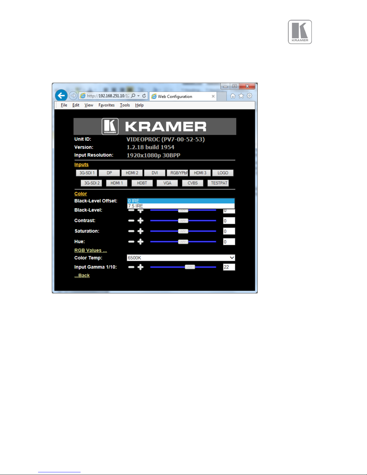
Menu items can be lists, sliders or alpha numeric fields.
A list item can be activated by moving the mouse pointer over the list item and clicking the left mouse
button. The list comes up and an item can be selected by moving the mouse pointer to the desired
value (here: 0 IRE) and clicking the left mouse button again.
A slider value can be changed by moving the mouse pointer over the slider, click and hold the left
mouse button and move the mouse to the right or left to decrease or increase the value. Also, the slider
can be controlled in single steps with the mouse wheel. Or by moving the mouse pointer over the – or +
fields and clicking the left mouse button..
Values can be entered directly in the field beneath the slider. Click into the field, enter the new value
through the PC keyboard and click with the left mouse button to any location outside the field to update
to the new value.
Page 22

© KRAMER ELECTRONICS LTD. Issue 1.10 16
th
of December 2015 22
Renaming the input channel is used as an example to explain the alpha numeric field changes. Move
the mouse pointer into the alpha numeric field and click on the left mouse button. The cursor can be
controlled with the right/left and back space keys of the PC keyboard. The new name for the input
channel can be entered.
The new name is stored when clicking with the left mouse button to any location outside the field.
Page 23

© KRAMER ELECTRONICS LTD. Issue 1.10 16
th
of December 2015 23
A page for file uploads is provided. Browse a firmware file (extension .bin) and select it. The path and
name will be shown in the field left to the Browse button. Now click the update button.
The unit set-ups can be backed up to a PC and restored later through web browser uploads. When
pressing the Backup button a typical file download dialog is started. The default name of a backup is
nvram.bin. It can be changed and stored on the PC in any location.
To restore a setting browse for the file. A selected file will be shown in the field left to the Browse
button. Now press the restore button.
Page 24

© KRAMER ELECTRONICS LTD. Issue 1.10 16
th
of December 2015 24
4.3.
Introduction
The front panel has keys and a jog wheel for OSD and local LCD menu navigation and direct keys for
input channel selection. The amount of input channels supported vary throughout the product line. All
other front panel controls are identical.
When applying power to the unit it starts up. This is indicated by the red Standby key flashing. Once the
unit is operational, the key is illuminated permanently.
1 – Standby key: By pressing the Standby key, the unit is put into standby mode. This is indicated by a
“STANDBY” message in the LCD with back light turned off.
2 – Input channel selection keys: All input channels can be directly selected. The active channel key is
illuminated.
3 – Test Pattern key: Directly activates a Test Pattern. Use the jog wheel to toggle trough the available
test patterns.
4 – Direct function keys: Four functions can be directly called by pressing the assigned key: Freeze
(stop/resume live video), PTZ (activate/deactivate Pan Tilt Zoom), Logo (show/skip a predefined logo),
Blank (blank the output screen/resume live video).
5 – Menu navigational keys: With the Menu/Sel key the menu is activated, this key also acts as an
Enter or Select key for menu changes. A jog wheel is used for menu navigation and changing values.
To exit the menu or any submenu press the Esc key or navigate to the Exit item and press the
Menu/Sel key or press the jog wheel.
6 – Front Panel LCD: The Menu is also shown on the LCD front panel.
6 – Jog wheel: The wheel is used for navigating through the menu system and making value changes.
The jog wheel has a push function. Pushing the knob has the same effect as pushing the Menu/Sel key.
With the following multiple key presses further functions can be applied:
Keypad unlock: Esc + Menu/Sel
Mode reset: Esc + CV
Factory reset: Esc + YPbPr (in live operation or at power up)
Set output mode to 720p: Esc + VGA
1
2 3 4 7 5
6
Page 25

© KRAMER ELECTRONICS LTD. Issue 1.10 16
th
of December 2015 25
The back panel features all input and output connectors, communication ports and the power supply
connector.
1 – HDBaseT 2 – Display Port input
3 – 2x HDMI (UHD/4k) input 4 – S/PDIF output
5 – DVI-U (DVI-D and YPbPr through a cable adapter) and VGA input 6 – 1x HDMI (HD) input
7 – Composite Video (BNC) 8 – HDBT output
9 – DVI/HDMI1 output and RS232 port
10 – HDMI2 output 11 – TCP/IP and 2x USB
12 – Power supply connector
1
2 3 4 5 6 7 8
9
10
11
12
Page 26

© KRAMER ELECTRONICS LTD. Issue 1.10 16
th
of December 2015 26
4.4.
Main Menu
The main menu lists the input channel select item, and 6 sub menus. The 6 sub menus are Output,
Colour, Geometry, Enhancement, Status and System.
On each menu page an Exit menu item is available to leave the menu or submenu.
Some adjustments are not applicable to all signal types or operating modes, in which case those non-
applicable functions will be greyed out and are not accessible.
Navigating the menu system or changing values is done with the jog wheel.
To set up your unit it is recommended that you follow this procedure:
Choose the correct output mode and parameters to suit your screen or projector.
For a LED screen set window size to match the LED module to be driven.
Select the correct input signal.
Set the input levels and features appropriately to optimize the appearance of your image.
Set any other parameters to suit your application.
Note: The processor is designed to have separate memories for all the settings in each section. All
Input parameters are specific to your chosen input channel and input signal type, they are not global to
the unit. If you change the settings in for example the composite video channel you will not affect the
settings you may have made in for example the DVI channel.
All Output parameters only affect the output, they do not affect any of the inputs but please note that the
appearance on the screen because it is the output these adjustments will appear to be global.
4.5.
Input
The list of available inputs can be scrolled through using the jog wheel. The new input is not selected
until the Menu key is pressed. The list of inputs include: Display Port, HDMI1, HDMI2, HDBaseT, DVI,
VGA, YPbPr/RGB, Composite Video and Test Pattern. Depending on the specific model some of these
inputs are not implemented and thus not present.
Test patterns can be generated by the nuit without needing an input connected.
When Test Pattern is selected as the input and menu is off, the required test pattern can be chosen by
the jog wheel.
4.6.
Output
This menu contains adjustments associated with setting up outputs from the unit. The items are
organized in four sub menus, Display Type, Gamma/Colour/Crush, Output Config and Output Window
Size. Use the jog wheel to scroll to the required item and press the Menu key. Output Window size is
not supported on models without the LED wall per edge-sizing feature.
4.6.1. Display Type
Output Mode
Settings: 640x480, 800x600, 1024x768, 1280x768, 1280x800, 1280x1024, 1400x1050, 1600x1200,
1920x1200, 480i, 576i, 480p, 576p, 1080i, 720p, 1080p, 2024x1080, 2560x1080, 2560x1440,
2560x1600, 3860x2160, 4096x2160
Set up the desired output resolution with output mode. The output mode setting should match the native
resolution of the imaging device to avoid double scaling.
Note: If selecting for an LED display choose a setting that is equal or greater than the display and then
use the window size adjustment to accurately scale to the LED wall.
The default output resolution as set by the factory or after a user issued factory reset is 720p.
Page 27

© KRAMER ELECTRONICS LTD. Issue 1.10 16
th
of December 2015 27
Frame Rate
Available settings: 60 Hz, 59.94, 50 Hz, 48 Hz, 25Hz, 24 Hz, 23.97, Auto
Not all settings may be available. Through the Frame Rates submenu frame rates can be banned from
the list, e.g. to cope with a display connected known to only support a subset of the rates above.
In auto mode the output frame rate follows the input frame rate with the limitation set under the Frame
Rates menu..
Signals with 23.97, 24Hz, 25Hz, 48Hz, 50Hz, 59.94Hz input modes get special treatment. Modes with
other refresh rates are displayed at 60Hz.
As a general rule first a mode with the exact same refresh rate is picked up. If that is not available the
mode with a refresh rate with a factor of 1.001 or 1/1.001 is taken. If that is not available a mode with
twice the rate is chosen. Next a mode with twice the rate with a factor of 1.001 or 1/1.001 is taken. If
that is also not available 60Hz (or 59.94Hz) is used.
E.g. 23.97Hz input modes will be output at 23.97Hz if the output resolution is set to a resolution that
supports 23.97Hz timings (check the output timing list). If no 23.97Hz exists but a 24Hz mode this
refresh rate will be used. If neither 23.97Hz or 24Hz exists but a mode at twice the rate, that one will be
used. If that does not exist either the 60Hz (or 59.94Hz) mode will be used.
A 25Hz input mode is output at twice the frame rate 50Hz.
50Hz input modes are displayed at 50Hz output rate.
The output frame rate can also manually be set to 23.97, 24Hz, 25Hz, 48Hz, 50Hz, 59.94Hz or 60Hz if
possible, i.e. such output modes are available.
I/O Lock
Available settings: Off, On, Genlock
If I/O Lock is switched off the output is run with a fixed refresh rate determined by the frame rate setting.
This setting will result in the output vertical refresh rate deviating from the input refresh rate, even if
both are nominally at the same rate. This causes occasional frame dropping or repeat.
If I/O Lock is set to On the output refresh rate is following the input video refresh rate if possible. If not,
the output is operated with a fixed refresh rate determined by the frame rate setting.
If I/O Lock is set to Genlock the output refresh rate is following the vertical sync of an externally
provided signal (GENLOCK BNC) if locking is possible. This is the case if the Genlock vertical sync rate
matches the vertical sync rate set in the output menu. Valid combinations are 50Hz/50Hz,
59.94Hz/59.94H and 60Hz/60Hz. If not the output is operated with a fixed refresh rate determined by
the frame rate setting.
Locking is achieved by locking the output clock to the input clock and deriving the VSync and HSync by
calculation.
The LCD menu main page indicates if the output signal is locked to the input signal (I/O Locked or
Genlocked) or in free run mode (Free Run).
If the unit is to be used as a clean switcher the settings for Frame Rate and I/O lock need to be chosen
carefully. Obviously, clean switching cannot be achieved if output frame rate locking to input video is
selected. Even if the to be switched input channels have signals attached with nominally the same
frame rate they always differ slightly and a new lock has to be established causing disturbances.
The following combinations of Frame Rate and I/O Lock settings determine the switching behaviour:
I/O Lock = On
(Lock to i/p video)
I/O Lock =
Genlock
I/O Lock = Off
(Free Run)
Auto Frame Rate
Never Clean
Always Clean
Depends on Inputs
Fixed Frame Rate (any)
Never Clean
Always Clean
Always Clean
Page 28

© KRAMER ELECTRONICS LTD. Issue 1.10 16
th
of December 2015 28
Note 1: The Auto Frame Rate vs Fixed Frame Rate function determines Genlock behaviour as well as
I/O Lock and Free Run behaviour. In Auto Frame Rate mode Genlock signals of 50Hz or 59.94/60Hz
are accepted, but in Fixed Frame Rate mode only a Genlock signal which matches the chosen Frame
Rate is accepted. So for example if the unit is fixed at 60Hz frame rate output it will not lock to a 50Hz
genlock reference, but will only lock to a 60Hz genlock reference.
Note 2: In Auto Frame Rate mode with Free Run Mode selected input switching may or may-not be
clean, this depends on how close the frame rates of the current and next input channel are.
Frame Rates
Settings: 60 Yes/No, 50 Hz Yes/No, 30/29.97Hz Yes/No, 24/23.98 Yes/No
Limits the possible output frame rates that can be selected. It is primarily to be able to limit the choices
available for the Auto refresh rate configuration.
Certain frame rates can be deactivated, so that output modes are not displayed with said rates. That is
to prevent the unit to send modes to a display which is not capable of displaying these frame rates.
4.6.2. Gamm/Color/Crush
Native Color Temp
Settings: 5500, 6500, 7500, 9300, 10000
Native Colour Temp allows the user to select from pre-configured colour temperatures to match the
display. If both Native Colour Temp set here in the Output menu and Colour Temp set in the Colour
menu are set to the same value, no conversion is performed.
Output Gamma
Settings: 1.0 to 3.0 in steps of 0.1
Output gamma allows to re-gamma video signals with pre-configured gamma values to match the
display. Input gamma and output gamma both default to 2.2. If they are both set to the same value,
there is no effect on the image.
Note: If e.g. an adjustment to reduce the level of red in the image is required, select a higher number for
the (input) Colour Temp in the Colour menu, or a lower number for the Native Colour Temp in the
Output menu.
Page 29

© KRAMER ELECTRONICS LTD. Issue 1.10 16
th
of December 2015 29
4.6.3. Output Config
This Menu provides items to configure the output port.
Display
Settings: DVI forced, DVI/HDMI
Internally, the display interface processes data at a full ten bits per colour. The colour depth on the
HDMI outputs is determined by the supported standard of the attached monitor or device when set to
DVI/HDMI.
For DVI 1.0 and HDMI 1.1/1.2 devices it is 24 bit, for HDMI 1.3 or later compliant devices it is up to 36
bit.
DVI forced will output with 24 bit colour depth irrespective of the supported standard of the attached
monitor.
HDCP
Settings: On, Off
HDCP encryption support on the output can be switched off. This means the unit pretends to be non
HDCP compliant on the DVI/HDMI output port and consequently does not encrypt data. At the same
time the unit pretends that the input ports are not HDCP compliant and either encrypted data is no
longer sent to the unit because it is not necessary or the unit will not show such content on the display.
DVI Colour Space and DVI Range
The colour space of the HDMI output ports can be set to RGB or YPbPr.
The range can be set to Default, Limited, and Full. When set to Default CEA output modes have limited
range, and VESA modes have full range. Therefore, an incoming limited range mode is either passed
through when the output is set to a CEA output mode or expanded when the output is set to a VESA
mode. An incoming full range mode is either compressed when the output is set to a CEA output mode
or passed through when the output is set to a VESA mode.
If the HDMI/DVI output does not behave as expected, e.g. because the HDMI display is not evaluating
AVInfoFrames properly, the range can be changed manually.
A limited video range is only using the following greyscale for video information - 8 Bit System: 0x10 ..
0xEF, 10 Bit System: 0x040 .. 0x03BF, 12 Bit System: 0x100 .. 0xEFF.
4.7.
Colour
This is an input channel menu containing adjustments associated with setting up inputs to the unit.
4.7.1. Black-Level Offset
Settings: 0 IRE, 7.5 IRE
Used to select 7.5 IRE black level set-up adjustment. Should always be set to 7.5 IRE for HDMI video
and NTSC video inputs and should usually be off for PAL analog video inputs.
4.7.2. Black-Level
Settings: -50 to 50 in steps of 1
Black level controls the offset applied to the video signal. (same as the brightness control on a TV)
Page 30

© KRAMER ELECTRONICS LTD. Issue 1.10 16
th
of December 2015 30
4.7.3. Contrast
Settings: -50 to 50 in steps of 1
Contrast controls the gain applied to the video signal.
4.7.4. Saturation
Settings: -50 to 50 in steps of 1
Control of video colour saturation, (applies individually to all video inputs but not computer input signals
or formats).
4.7.5. Hue
Settings: -50 to 50 in steps of 1
Control of the hue of the colour of a video signal, Normally only needed when playing NTSC signals or
video transferred poorly from an NTSC origination. (applies to all video inputs but not computer input
signals or formats).
4.7.6. RGB values
This is a user-defined colour temperature setting whereby individual R,G,B gain (white balance) and
offset/bias (black balance) can be set so as to accurately calibrate a particular input to the display
device.
4.7.7. Colour Temp
Settings: 5500, 6500, 7500, 9300
A preset range of Colour Temperature which allows the user to select from pre-configured colour
temperatures to match the colour temperature of the incoming signal. If both Colour Temp set here in
the Colour menu and Native Colour Temp set in the Output menu are set to the same value, no
conversion is performed.
4.7.8. Input Gamma
Available settings: Gamma 1.0, Gamma 1.5, Gamma 2.2, Gamma 2.8
Set this value to match the native gamma of the input signal.
Input gamma and output gamma both default to 2.2. If they are both set to the same value, there is no
effect on the image.
4.8.
Geometry
This menu contains adjustments associated with setting up position, aspect ratio and scale of the input
signal..
4.8.1. Picture Format
Settings: Original, Full Screen, Crop, Anamorphic
Picture Format allows a user to select the displayed aspect ratio where the signal input is different to
the display panel’s natural aspect ratio.
Note that some aspect ratios may not be applicable to all signal types, in which case selecting a non-
applicable aspect ratio conversion will have no effect on the displayed image. E.g. when a 16:9 image
is displayed on a 16:9 panel all settings give an identical full screen image.
Page 31

© KRAMER ELECTRONICS LTD. Issue 1.10 16
th
of December 2015 31
Original preserves the aspect ratio of the incoming image and scales the image to fit into the size of
the panel. Dependant on the aspect ratio of the panel the image is either bordered by the right/left side
or bottom/top of the panel. Non-used areas of the panel are displayed black (letterboxed).
Full Screen scales the image to the size of the panel without preservation of the aspect ratio.
Crop preserves the aspect ratio and scales the image to fit the screen. Dependant on the aspect ratio
of the panel either the top/bottom or right/left areas of the image are cropped.
Anamorphic scales the input image such that it is displayed with a 16:9 aspect ratio when displayed on
the screen. The image is further scaled to fit into the size of the panel. Dependant on the aspect ratio of
the panel the image is then either bordered by the right/left side or bottom/top of the panel. Non-used
areas of the panel are displayed black (letterboxed).
4.8.2. Overscan
Settings: 0 to 10 in steps of 1
Overscan is used to slightly zoom into the image. Thus, the border area of an image is no longer
displayed on the screen. This cuts off unwanted features at the top or bottom from e.g. head switching
in legacy video images.
4.8.3. Pan Tilt Zoom
This menu provided settings to zoom and shrink the image, as well as panning within the image.
Pan Tilt Zoom (PTZ) can be switched on or off.
PTZ settings can be saved per mode or globally, i.e. if applied globally the same PTZ settings are
applied when switching input channels or changing the input mode.
The Zoom slider allows to zoom into the image or shrink it.
When Aspect Lock is set to On the separate slider for zooming vertically is greyed out and the
horizontal zoom or shrink factor is used as vertical factor as well. The aspect ratio is preserved.
When Aspect Lock is Off horizontal and vertical scaling factors can be chosen separately.
With the Pan and Tilt sliders panning within the image in horizontal and vertical direction is possible. Off
raster panning is allowed, i,e, the image can be shifted outside the active area of the display.
For convenience the PTZ settings can be reset with one button.
Page 32

© KRAMER ELECTRONICS LTD. Issue 1.10 16
th
of December 2015 32
4.9.
Enhancement
The enhancement menu provides image enhancement functions. Note that the enhancement settings
apply to individual video input signal channels only but not to computer graphics signals.
4.9.1. Sharpness
Settings: -4 to 4 in steps of 1
Control of the sharpening enhancement filters' levels. These are peaking filters to improve high-
frequency response. Note that setting this control too high on a signal which already has good high
frequency response will cause ringing or ghosting.
4.9.2. Detail
Settings: 0, 1, 2, 3
This filter provides powerful 2D image enhancement which can be used to greatly improve detail
definition and clarity without causing image ringing or ghosting. It improves both horizontal and vertical
detail. Correct setting of the detail enhance filter can make SD signals look virtually indistinguishable
from true HD. At setting 0 the filter is switched off, with setting 3 providing the highest effect.
Page 33

© KRAMER ELECTRONICS LTD. Issue 1.10 16
th
of December 2015 33
4.10.
System
This selection contains functions which are more applicable to system operation than to picture
adjustment.
4.10.1. User
Settings: USER 1, 2, 3, 4
A predefined setting stored under a user name can be selected. Several settings of the unit can be
stored under a user name. Thus, different users can store their preferred settings and recall these
profiles by picking up their user name from this menu.
Note: Using the Web interface, (any number of) settings can also be stored/restored to/from a PC disc
drive.
4.10.2. Names/Profiles
The Names/Profiles menu provides input masks to rename the generic input channels and user names.
User names and input channel names can be changed to any word with a maximum of 12 alpha
numeric characters with a value range of 0-9, A-Z and blank.
The unit itself can be given a name. The default name is VIDEOPROC. This name followed by the MAC
address is used by the web server and being displayed in the unit line of the weg page.
4.10.3. Input Config
Inputs can be configured through the following sub-menus:
Analog Inputs
VGA Setup:
A button for resetting the adjustments for a given mode to factory defaults is provided. Press this button
if phase, clock and positional settings have been set beyond a point of return.
Frequency (Clock) and phase can also be altered manually. Also the vertical and horizontal position
can be fine adjusted.
The Color Space and (greyscale) Range can be chosen. The color space can be set to RGB or YCbCr,
The greyscale range can be reduced by switching from full to limited (see range values discussed in the
output config section).
The preferred video mode can be selected in the EDID Input Format menu. This setting can force the
source to output a certain video mode provided the driver of the graphic card takes notice of the
preferred timing in the EDID. The PC most likely has to be rebooted for the driver to take notice.
RGB/YPbPr Setup:
Same as VGA Setup, except there is no concept of EDID with component video and thus no EDID Input
Format menu.
RGB/YPbPr Setup:
CCS is a filter to reduce luminance to chrominance cross talk of composite video signals (only) which
appears as a coarse rainbow pattern or random colours in regions of fine details.
Page 34

© KRAMER ELECTRONICS LTD. Issue 1.10 16
th
of December 2015 34
Digital Inputs
DP Config:
The automatic HDMI Color Space and Range settings can be overwritten in this menu. The Range
attribute can be overwritten to limited or full range in case the AVInfoFrames are wrong. The color
space can be set to RGB or YCbCr if the Auto setting does not give the desired result.
The EDID can be configured to pretend certain deep color capability. The unit can process color depth
of 24/30bit per channel. Deep Color can be off (source outputs 24bit) or on (source decides to output
30bit). The source output of 24bit or 30bit color depth can be monitored by means of the web server.
The preferred video mode can be selected in the EDID Input Format menu. This setting can force the
source to output a certain video mode provided the driver of the graphic card takes notice of the
preferred timing in the EDID. The PC most likely has to be rebooted for the driver to take notice.
HDMI 1, HDMI 2, HDBT Config:
The automatic Color Space and Range settings can be overwritten in this menu. The Range attribute
can be overwritten to limited or full range in case the AVInfoFrames are wrong. The color space can be
set to RGB or YCbCr if the Auto setting does not give the desired result.
The EDID can be configured to pretend certain deep color capability. The unit can process color depth
of 24/30/36bit per channel. Deep Color can be off (source outputs 24bit) or on (source decides to output
either 30bit or 36bit). The source output of 24bit, 30bit or 36bit color depth can be monitored by means
of the web server.
The preferred video mode can be selected. This setting may force the source to output a certain video
mode provided the driver of the graphic card takes notice of the preferred timing in the EDID. The PC
most likely has to be rebooted for the driver to take notice.
The DDC can be taken off line. When setting HDCP Input to off the unit pretends to be non HDCP
compliant forcing the source to not encrypt data which is not copy protected. When the HDMI HDCP
capability is set to off through the output config menu, i.e. it outputs unencrypted by all means this
menu item is greyed out. In fact HDCP is set to off on the input internally.
DVI and HDMI 3 Config:
The automatic Colour Space and Range settings can be overwritten in this menu. The Range attribute
can be overwritten to limited or full range in case the AVInfoFrames are wrong. The colour space can
be set to RGB or YCbCr if the Auto setting does not give the desired result.
Deep Color can be off (source outputs 24bit) or on (source decides to output either 30bit or 36bit). The
source output of 24bit, 30bit or 36bit color depth can be monitored by means of the web server.
The DDC can be taken off line. When setting HDCP Input to off the unit pretends to be non HDCP
compliant forcing the source to not encrypt data which is not copy protected. When the DVI HDCP
capability is set to off through the output config menu, i.e. it outputs unencrypted by all means this
menu item is greyed out. In fact HDCP is set to off on the input internally.
The preferred video mode for DVI input can be selected. This setting may force the source to output a
certain video mode provided the driver of the graphic card takes notice of the preferred timing in the
EDID. The PC most likely has to be rebooted for the driver to take notice.
HDMI Audio Support:
The audio capabilities of the HDMI port can be configured by means of overwriting the EDID. The unit
described in this manual is part of an audio/video processing chain and devices behind the unit may not
be able to cope with advanced audio. The unit can signal the source to match with the audio
capabilities of the display (setting Match Display 1/2), or to be S/PDIF friendly. If the unit is set to Full
the capabilities of the unit are communicated by means of the EDID to an audio source.
Page 35

© KRAMER ELECTRONICS LTD. Issue 1.10 16
th
of December 2015 35
Test Pattern Setup:
When the menu is off the test pattern can be toggled through by turning the jog wheel. For unit control
through a web browser or to set up a certain default test pattern please use the input configuration
menu.
Custom test patterns loaded into the file system of the unit through the web interface, can be accessed
through the same means.
A test tone to accompany the test pattern can be switched on and off.
Switching Transition:
When switching input channels by default the last frame of the prior displayed image is frozen and
displayed until a stable image of the new input channel can be shown.
The switchover process is supposed to be as seamless as possible. The source and monitor add
switching noise due to unforeseeable activity of the firmware in said devices. By default the unit in auto
frame rate switching and I/O lock mode. In order to get a best smooth switching result with the source
and monitor I/O lock and auto frame rate switching have to be switched off in the Output/Display Type
menu.
The switching transition of the unit can be set to Freeze and Blank..
Freeze halts the prior channel image until the new channel image is stable.
Blank switches the output to show a black screen instead of the last channel image.
4.10.4. Menu Settings
This menu provides an item to change the menu display time, i.e. the time after which the LCD menu is
switched back to the main status screen again with no user interaction.
The menu language can be altered and the keypad can be locked. To unlock the keypad a combination
of keys has to be pressed at the same time. The locking of the keyboard is accompanied by the
message that the keypad is locked and which keys need pressing to unlock the unit. When successfully
unlocking the keypad the message shows up: Keypad unlocked.
The backlight level of the LCD can be set in this menu.
The colour of the web pages can be changed from dark to light to adjust viewing experience to match
the ambient conditions.
4.10.5. Network Settings
The Network Settings menu allows to configure the unit´s TCP/IP address. Under Address Type a static
or DHCP leased address can be chosen. The static address, gateway address and netmask needs to
be entered manually.
The Network Settings menu has a section with information on the DHCP Status and IP address
assigned to the board, as well as the fixed MAC Address programmed into the unit. The DHCP status is
Off when static assignment is used or it displays an address when DHCP has leased an address
accordingly or it is None assigned if the lease was not successful.
Push the Apply button for setting changes to become effective.
Note: When changing from DHCP to Static mode or vice versa it is strongly recommended that the unit
is powered down after such a change, then powered back up, so that it is properly recognised by other
devices on the network.
Page 36

© KRAMER ELECTRONICS LTD. Issue 1.10 16
th
of December 2015 36
4.10.6. Security Settings
The password for ftp and web access to the unit can be changed in this menu.
4.10.7. Factory Defaults
This button let you restore all settings to the default values of the unit, thus, provide a means to get
back to a known (good) system state. A requestor will come up and ask to confirm prior to actual
restore.
4.11.
Status
This menu provides status information of the connections to the HDMI2, DVI/HDMI1 and HDBT outputs.
The unit reads the EDID of the attached monitor and makes decision based on its capabilities and the
configuration of the unit (Deep Colour and HDCP support). The type of attached monitor (DVI or HDMI),
video bit depth (8, 10 or 12 bit per colour channel) and HDCP encryption (on/off) is displayed.
Page 37

© KRAMER ELECTRONICS LTD. Issue 1.10 16
th
of December 2015 37
FIRMWARE UPDATE
5.1.
Introduction
The latest firmware version for your processor is published on our website at the bottom of this page:-
http://www.calibreuk.com/HQViewDownloads.htm
Save the correct file for your specific unit (model number) to your computer.
There are two methods of updating. First, through a TCP/IP connection by means of the web server
and second, through the USB port by means of a USB pen drive.
5.2.
Updating Firmware
Update by means of the web server: See section on web browser control.
Update by means of a USB pen drive: Copy the firmware file with extension .bin on your USB pen drive.
The firmware files typically come with a file name pv7update-XXXX.bin with XXXX being the build
number of the firmware release. Rename the file to pv7update.bin. This step is important. The unit will
only recognize firmware update files with this specific name.
Power off the unit and plug the USB pen drive into one of the USB ports of the unit to be updated.
Power on the unit. The following messages will come up on the LCD. Remove the USB pen drive once
this is requested.
UPDATING…
TRANSFERING -> REMOVE USB DRIVE -> VERIFYING CHECKSUM -> EXTRACTING
STARTING…
Note: Not all USB pen drives in the market are compatible with PV7. All 16GB and 32GB pen drives
being tested so far have been identified as not compatible. The following USB pen drives have been
proven to work:
Transcent 8GB USB3
Kingston 8GB USB2.
Intenso 8GB 24-1008
Page 38

© KRAMER ELECTRONICS LTD. Issue 1.10 16
th
of December 2015 38
ENVIRONMENTAL AND EMC
6.1. Recommended Operating Conditions
Temperature 0oC to 40oC
Humidity (non condensing) 5% to 95%
6.2. Storage
Temperature -25oC to +85oC
Humidity 0% to 95%
6.3. CE and FCC Compliance
CE: This product complies with the requirements of 2004/108/EC Electromagnetic
Compatibility Directive, and 2006/95/EC Low Voltage Directive. Compliance is to
EN55022 Class A.
FCC: WARNING: This equipment has been tested and found to comply with the limits for a
Class A digital device pursuant to Part 15 of the FCC Rules. These limits are designed
to provide reasonable protection against harmful interference when the equipment is
operated in a commercial environment. This equipment generates uses and can
radiate radio frequency energy and, if not installed and used in accordance with the
instruction manual, may cause interference to radio communications. Operation of
this equipment in a residential area is likely to cause interference in which case the user
will be required to correct the interference at their own expense.
The user is cautioned that changes and modifications made to the equipment without
approval of the manufacturer could void the user’s authority to operate this equipment.
It is suggested that the user use only shielded and grounded signal cables to ensure
compliance with FCC rules.
6.4. PAT Testing
Earth continuity testing under PAT regulations shall be done to the product with 8A or 10A only. A test
with 25A may damage the product.
In fact, VP is IT equipment and the IEE Code of Practise to check earth continuity suggests an
alternative 20-200mA test. If the PAT tester does not provide this method and a high current test is to
be used instead a 8A or 10A test will be acceptable under the same IEE Code of Practise (a minimum
of 1.5 times of the VP internal 5A fuse).
You have to be careful where you connect the earth bond test lead when using 8A or 10A. It is to the
metal chassis that you must connect the test lead (mains earth). DO NOT CONNECT to the connectors
of the rear panel (signal earth). The VP may never work again.
 Loading...