

Page 1

Kramer Electronics, Ltd.
USER MANUAL
Model:
VP-747T
Presentation Switcher Control P anel
Page 2

Contents
i
Contents
1 Introduction 1
1.1 About the VP-747T Presentation Switcher Control Panel 1
2 Getting Starte d 2
2.1 Quick Start 2
3 Overview 3
4 Your VP-747T Presentation Switcher Co n tro l Pa n el 4
5 Installing in a Desktop 8
6 Installing on a Rack 10
7 Connecting the VP-747T 11
7.1 Setting the Machine # 12
7.2 Connecting to the VP-747 by Wired Connection 13
8 Operating the VP-747 using the VP-747T 14
8.1 Using the VP-747T WIPE DIRECTION Buttons 14
8.2 Making the Transition 15
8.2.1 Making a Transition Manually 15
8.2.2 Making a Transition Automatically 15
9 Technical Specifications 15
Figures
Figure 1: VP-747T Present a ti o n S witcher Control Pa ne l 5
Figure 2: VP-747T Present a ti o n S witcher Control Pa ne l (Si de Panel)
7
Figure 3: Cut Out Dimensions 8
Figure 4: Inserting the VP-747T into the Prepared Cut Out Opening
8
Figure 5: Inserting the Mounting Brackets through the Bracket Slits
9
Figure 6: Securing the VP-747T into the Prepared Cut Out Opening
9
Figure 7: Connecting the VP-747T 12
Figure 8: Connecting the VP-747T RS-485 Ports
13
Tables
Table 1: VP-747T Presentation Switcher Control Panel Features 6
Table 2: VP-747T Presentatio n S witcher Control Pa ne l (Side Panel) Features
7
Table 3: Defining the WIPE DIRECTIONS Buttons
14
Table 4: Technical Specifications of the VP-747T 15
Page 3

Introduction
1 1
1 Introduction
Welcome to Kramer Electronics! Since 1981, Kramer Electronics has been
providing a world of uni que, creat iv e, an d aff ordabl e s oluti ons to t h e vast range
of problems that confr ont th e video, audio, presentation, and broadcasting
professional on a daily basis. In recent years, we have redesigned and upgraded
most of our line, making th e best ev en be tter! Our 1, 000-plus different models
now appear in 11 grou ps
1
Congratulations on purchasing your Kramer VP-747T Presentation Switcher
Control Panel, which is ideal for staging events, as well as:
that are clearly defined by function.
• Presentation applications that require a preview option
• Projection systems in confe rence rooms, board rooms, auditor iums, hotels,
and churches
1.1 About the VP-747T Presentation Switcher Control Panel
The Kramer VP-747T Presentation Switcher Cont r ol Panel is used to control
the VP-747 Universal Presentat ion Matrix Switcher / Scaler
2
Note that the VP-747 needs firmware package Mast er FW 1.03 (V er. 1.03 or
higher) to work with the VP-747T.
. The Kramer
VP-747T lets you remotely control switcher functions such as input selection,
transition effects (that include cut, fade, and wipes) and transition speed.
The package includes: the VP-747T, gooseneck lamp, null-modem adapter,
power supply, rack ears kit
3
, table-top brackets, 2 mini-XLR connectors and this
user manual
4
.
1 GROUP 1: Distribution Amplifiers; GROUP 2: Switchers and Matrix Switchers; GROUP 3: Control Systems;
GROUP 4: Format/Standards Converters; GROUP 5: Range Extenders and Repeaters; GR OUP 6: Specialty AV Products;
GROUP 7: Scan Converters and Scalers; GROUP 8: Cables and Connectors; GROUP 9: Room Connectivity;
GROUP 10: Accessories and Rack Adapters; GROUP 11: Sierra Products
2 A true multi-standard video to graphics scaler and seamless switcher with 2 DVI/HDMI inputs as well as 8 universal inputs
comprised of 5 BNC connectors each of which can accommodate a composite video, s-Video (Y/C), component video
(RGB/YUV), RGBS, or RGBHV signal. It has dual scalers, one for the preview and the other for the program output. Dual
scalers are required to do "live" seamless transitions from one source to another
3 A pair of rack ears, two spacers and ten screws
4 Download up-to-date Kramer user manuals from the Internet at this URL: http://www.kramerelectronics.com
Page 4
KRAMER: SIMPLE CREATIVE TECHNOLOGY
Getting Started
2
2 Getting Started
We recommend that you:
• Unpack the equipment carefully and save the original box and packaging
materials for possible future shipment
• Review the contents of this user manual
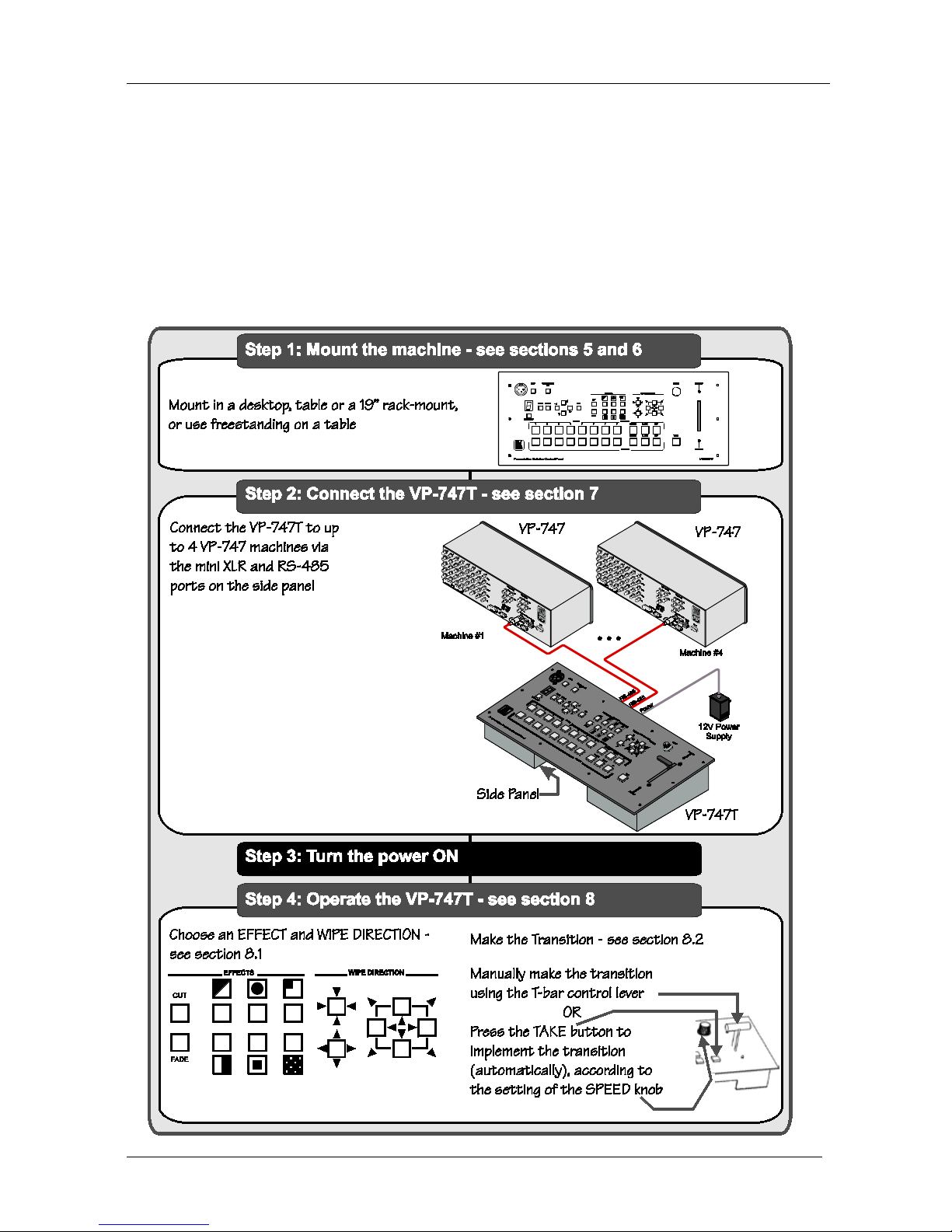
2.1 Quick Start
This Quick start chart summarizes the basic steps when connecting a VP-747T:
Page 5

Overview
3 3
3 Overview
The VP-747T is a unique presentation switcher control panel dedica t ed
specifically to control the VP-747
1
• Enables special effect transitions between two sources via a robust T-bar
(used for manual control of transition speeds). Alternatively, the effect can
be implemented via a TAKE button, with a potentiometer to set the
transition speed
. It is ergonomically and aesthetically
designed in a rugge d, prof ess i onal 19" 4U rac k-mountable me ta l e nclosure with
the button layout in the style of the VP-747. In particular, the VP-747T:
• Features single button access to all inputs
2
• Features dedicated single button actions for special effect selection,
immediate freezing and bl an king, PIP dis pl ay, and th e ch oic e of wi pe
direction
—both for the Preview an d f or
the Program output—and the buttons have removable transparent caps to
allow labeling
• Has the user menu—conveniently located on the VP-747T panel—for
complete control of the VP-747
via its Preview OSD
• Consol can be simultaneously connected to up to four VP-747 machines,
using two mini XLR conn ectors an d tw o t erminal bl ock c onnectors . The
communication is via RS-485, thus allowing the panel to be locat ed more
than 1km from each VP-747
• Has an RS-232 port for field upgrading of its fi rmw ar e
• With its angled faceplate, may be used freestanding on a table, or mounted
in a desktop or in a 19” rack (when your switcher is rack-mounted near to
the source devices, you can conveniently place the VP-747T
on a table or
desk away from the equipment rack)
• Has a gooseneck lam p (in clu ded) that can be plugged into the cons ol for
use in low lighting environments
• Is power ed by a 12V DC s ource
1 The VP-747 is also backward compatible to the VP-727T
2 Has two sets of input buttons: one that routes the input to the "PROGRAM" output and the other that routes to the
"PREVIEW" output
Page 6
KRAMER: SIMPLE CREATIVE TECHNOLOGY
Your VP-747T Presentation Switcher Control Panel
4
To achieve the best performance:
• Conn ect only good qu ali ty c onnec tion cabl es
• Avoid interference from neighboring electrical appliances, make sure not to
block the ventilation holes and position your VP-747T
away from
moisture, excessive sun light and dus t . Be sure t o posi ti on it s t raight in the
correct horizontal position on the table, desk or rack
4 Your VP-747T Presentation Switcher Control Panel
Figure 1 and Table 1 define the front panel of the VP-747T:
Page 7

Your VP-747T Presentation Switcher Control Panel
5
Figure 1: VP-747T Presentation Switcher Control Panel
Page 8

KRAMER: SIMPLE CREATIVE TECHNOLOGY
Your VP-747T Presentation Switcher Control Panel
6
Table 1: VP-747T Presentation Switcher Control P ane l F e atur e s
# Feature Function
1 LAMP Button Toggles the gooseneck lamp ON/OFF
2 MENU Button Displays the OSD Menu screen (or moves to the pre vious level in the O SD menu)
3 ENTER Button Moves to the next level in the OSD menu
4 CONTROLLER ON
Button
Toggles the VP-747T Presentation Switcher Control Panel ON/OFF
5
OSD
NAVIGATION
Buttons
Toggles within each level 2 command / decreases the range by one step
6
Moves up one step (in the same level) in the OSD menu
7
Toggles within ea ch leve l 2 co mmand / increa ses t he range by one step
8
Moves down one step (in the same level) in the OSD menu
9 OSD Button Activates/deacti vates access to the OSD Menu
1
10 FADE 2 Button Selects a dissolved transition from the PREVIEW to the PROGRAM output
11 CUT
2
Selects an instantaneous transition from the PREVIEW to the PROGRAM output Button
12
TRANSITION Buttons
3 5,
Selects a WIPE transition effect
13
Selects a DIAGONAL transition ef fect
14
Selects a CIRCLE transi tion e ff ec t
15
Selects a SQUARE transition effect
16
Selects a CORNER transit ion effec t
17
Selects a CHESSBOARD transi tion e ffe ct
18 WIPE DIRECTION
Buttons
Choose the dire ct ion of t he e ffec t4: inwards, ou tward s, “lef t t o r ight” , “ right to
left”, “up” or “down” (see
Section 8.1
19 ) SPEED Knob Adjusts the TAKE button transition spee d
20 TAKE Button
5
Pressing TAKE causes the trans ition to occur autom atic ally
21 PREVIEW LED Lights when the T-bar Controller is directed upwards
22 PREVIEW LED Lights when the T-bar Controller is directed downwards
23 T-bar Control Lever
6
Slide to manually implement the eff ect u sing t he T-bar handle
24
PROGRAM
Buttons
PIP Toggles the p ictur e-in-picture func tion on an d o ff
25 BLANK Toggles between a b lank screen and th e s elec ted input
26 FREEZE Freezes the output video image ( toggle)
27 INPUTS Selects one o f the sou rces: R /PR, G/Y/CV, B/PB/C, HS/CS, VS (from 1 to 8)
28
PREVIEW
Buttons
PIP Toggles the p ictur e-in-picture func tion on an d o ff
29 BLANK Toggles betwee n a b lank screen and th e s elec ted input
30 FREEZE Freezes the output video image ( toggle)
31 INPUTS Selects one o f the sou rces: R /PR, G/Y/CV, B/PB/C, HS/CS, VS (from 1 to 8)
32 MACHINE # Button Pressing selects which MA CH INE # is c ontrolled
33 7-segment LED Display Shows the MACHINE #
34 Lamp Connector Connec ts to t he goos en eck l a mp
1 The LCD is not affected by the OSD setting
2 Only for setting up the unit for the effect. The effect will only occur when the Take button is pressed, or the T-bar is moved
3 Select a specific effect for the transition from the PREVIEW output to the PROGRAM output
4 From where the effect starts
5 The effect is only seen in PROGRAM Mode. The PREVIEW screen will blank during the transition
6 An alternative to using the TAKE button
Page 9

Your VP-747T Presentation Switcher Control Panel
7
Figure 2 and Table 2 define the side panel of the VP-747T:
Side Panel
Figure 2: VP-747T Presentation Switcher Control Panel (Side Panel)
Table 2: VP-747T Presentation Switcher Control Panel (Side Panel) Features
# Feature Function
1
TO VP-747
MACH. # 1 RS-485 Mini
XLR Connector
Connects to the Mini X LR Connector on the VP-747 which is recognized as
machine # 1
2 MACH. # 2 RS-485 Mini
XLR Connector
Connects to the Mini XLR Connector on the VP-747 which i s recognized as
machine # 2
3 MACH. # 3 (A B G)
RS-485
1
3-pin Terminal
Block Connector
Connects to the Mini XLR Connector port on the VP-747 w hich is
recognized as machine # 3
4 MACH. # 4 (A B G)
RS-485
1
Connects to the Mini XLR Connector on the VP-747 which i s recognized as
machine # 4 3-pin Terminal
Block Connector
5 RS-232 9-pin D-sub Connector Connects to the PC for upgrading the fi rmware
2
6 12V DC +12V DC connector for powering the unit
1 Pin G is for the Ground connection, which is sometimes connected to the shield of the RS-4 85 cable. In most applications,
the ground is not connected; pins B (-) and A (+) are for RS-485
2 Download the latest version of firmware and installation instructions at http://www.kramerelectronics.com
Page 10

KRAMER: SIMPLE CREATIVE TECHNOLOGY
Installing in a Desktop
8
5 Installing in a Desktop
This section describes how to install the VP-747T in a desktop
1
To install the VP-747T in a desktop:
.
1. Cut an opening in the de s kt op—ma king the cut out on a wooden surface
using a sabre saw or a keyhole saw—at the loca tion where you want to
insert the VP-747T.
Figure 3 illustrates the cut out template (not to scale)
definin g the surfa ce that you have to cut out to install your VP-747T.
Figure 3: Cut Out Dimensions
2. Carefully ins ert the VP-747T unit into the prepared cut out opening, as
illustrated in
Figure 4.
Figure 4: Inserting the VP-747T into the Prepared Cut Out Opening
1 Alternatively, you can use it freestanding on a table, or mounted in a 19” rack (see Section 6)
Page 11

Installing in a Desktop
9
3. Insert the two mounting brackets through the bracket slits on both sides of
the VP-747T unit (see
Figure 5 ).
Figure 5: Inserting the Mounting Brackets through the Bracket Slits
4. Be sure that the upper outer rim is situated parallel to the edge of the desktop.
5. Screw the mou nting butt erfly sc rews until they reach the desktop s urface
(from the underne ath).
6. Tighten the locking butterfly screws to lock the mounting butterfly screws.
The VP-747T unit is now secure d in place, as illustrated in
Figure 6 .
Figure 6: Securing the VP-747T into the Prepared Cut Out Opening
Page 12

KRAMER: SIMPLE CREATIVE TECHNOLOGY
Installing on a R ack
10
6 Installing on a Rack
This section provides instructions for rack mount ing the unit.
Page 13

Connecting the VP-747T
11
7 Connecting the VP-747T
To connect the VP-747T to up to four VP-747 machines, as the example in
Figure 7 illustrates, do the following15F1:
1. Connect the “TO VP-747” mini XLR connector of the VP-747T (by
one-to-one connection) to the VP-747, as follows:
MACH. # 1 to th e m ini XLR connec t or of th e VP-747 which will be
recognized as machine # 1
MACH. # 2 to the mini XLR connector of the VP-747 which will be
recognized as machine # 2
2. Connect the “TO VP-747” 3-pin ter minal block ports of the VP-747T (by
wired connection) to the VP-747, as follows (see section
U 7.2U):
MACH. # 3 to the mini XLR connector of the VP-747 which will be
recognized as machine # 3
MACH. # 4 to the mini XLR connector of the VP-747 which will be
recognized as machine # 4
3. Set the “T-Bar Optimization” mode in the “Transition” menu of the
VP-747 to On.
4. Connect the 12V DC power adapter to the power socket and connect the
adapter to the mains electric ity (not illustrated in
UFigure 7 U).
If you want to control several units simult aneo u sly, press the MACHINE #
button until the letter A is selected in the 7-segment LED display (A=ALL).
One of the units must be connected to port #1 for units to be controlled
simultaneously.
1 Switch OFF the power on each device before connecting it to your VP-747T. After connecting your VP-747T, switch on its
power and then switch on the power on each device
Page 14

KRAMER: SIMPLE CREATIVE TECHNOLOGY
Connecting the VP-747T
12
Figure 7: Connecting the VP-747T
7.1 Setting the Machine #
The VP-747T automatically recognizes the MACHINE # of each VP-747 unit.
For example, the VP-747 unit that is connected to the “TO VP-747” RS 485
port MACH. # 3 is rec ognized as th e third VP-747 unit: MACHINE # 3.
To access this particular VP-747 unit from the VP-747T, press the MACHINE
# button
1
until the number 3 is selected in the 7-segment LED display
2
.
1 Item 32 in Figure 1 and Table 1
2 Item 33 in
Figure 1 and Table 1
Page 15

Connecting the VP-747T
13
7.2 Connecting to the VP-747 by Wire d Connection
When connecting the “TO VP-747” RS 485 3-pin terminal block ports of the
VP-747T, to the respective VP-747 machine, as illustrated in
Figure 8 , connect
the:
• “A” (+) PIN of the VP-747T to the “A” (+) PIN of the VP-747
• “B” (+) PIN of the VP-747T to the “B” (+) PIN of the VP-747
• If shielded twisted pair cable is used, the shield may be connected to the
“G” (Ground) PIN on one of the units
VP-747T Side Panel
VP-747 Mini XLR Connecto r
RS-485 PINOUT
G
B
A
_
+
Figure 8: Connecting the VP-747T RS-485 Ports
Page 16

KRAMER: SIMPLE CREATIVE TECHNOLOGY
Operating the VP-747 using the VP-747T
14
8 Operating the VP-747 using the VP-747T
To operate the VP-747 via the VP-747T, set the VP-747 “Optimize T-bar”
mode in the “Transition” menu to On.
For details of how to operate the VP-747 via the OSD Menu, LCD Display,
ETHERNET, and/or RS-232, including using the TAKE button, refer to the
VP-747 user manual
1
• Use the WIPE DIRECTION buttons, see section
. For details of how to:
8.1
• Adjust the transition speed, see section
8.2
8.1 Using the VP-747T WIPE DIRECTION Buttons
To set the wipe direction, use the WIPE DIRECTION
buttons2 (see Table 3):
Table 3: Defining the WIPE DIRECTIONS Buttons
EFFECTS WIPE DIRECTIONS
Wipe
Choice of four
directions (only
one button is
selected)
Down
Up
Left to right
Right to left
Diagonal
Choice of four
directions (two
buttons are
selected
simultaneously)
Circle
In
Out
In
Out
Square
In
Out
In
Out
Corner
Choice of four
directions (two
buttons are
selected
simultaneously)
Chessboard
In
Out
Each block performs as shown
in the “Square” above
1 Download up-to-date Kramer user manuals from the Internet at: http://www.kramerelectronics.com
2 Item 18 in Figure 1 and Table 1
Page 17

Technical Specifications
15
8.2 Making the Transition
You can make the transition in two ways:
• Manually, for each separate transition using the T-bar control lever
1
• Automatically, via the TAKE button, which implement s the transition at the
pace set by the SPEED
2
8.2.1 Making a Transition Manually
knob
To make the tra ns ition, manually:
• Slide the T-bar handle upwards
3
or downwards
4
8.2.2 Making a Transition Automatically
To make the transition, automatically:
• Rotate the SPEED knob
2
to the right (increasing the transition speed) or to
the left (decreasing the transit ion speed). When the knob is turned t o th e
extreme counter-clockwise position (off), the switch will be engaged to turn
the knob off. In this posi ti on, the speed setting is controlled via th e set ting
in the VP-747 OSD menu
• Pressing the TAKE button
5
9 Technical Specifications
causes the transition to occur automatically
Table 4
includes the technical specifications:
Table 4: Technical Specifications
6
PORTS:
of the VP-747T
2 sets of mini XLR ports
2 sets of RS-485 3-pin terminal block ports
CONTROLS: Front panel bu ttons, min i XLR and RS-485
POWER SOURCE: 12V DC, 280mA
DIMENSIONS: 19” (W), 3.4” (D), 4RU (H) rack mountable
7
WEIGHT:
1.58kg (3.5lbs) approx.
ACCESSORIES: Gooseneck lamp, 2 mini XLR connectors, power supply, rack ears
kit
8
1 Item 23 in
, and table-top brackets
Figure 1 and Table 1
2 Item 19 in
Figure 1 and Table 1
3 The PREVIEW LED lights (item 21 in
Figure 1 and Table 1)
4 The PREVIEW LED lights (item 22 in
Figure 1 and Table 1)
5 Item 20 in
Figure 1 and Table 1
6 Specifications are subject to change without notice
7 48.2cm (W), 8.6cm (D), 17.7cm (H)
8 A pair of rack ears, two spacers and ten screws
Page 18

KRAMER: SIMPLE CREATIVE TECHNOLOGY
16
LIMITE D WA RRANTY
WHO IS PROTECTED?
WHA T IS COVERED AND WHA T IS NOT COVERE D
WHA T WE WILL P A Y FOR A ND WHA T W E WILL NOT P A Y FOR
HOW YOU CAN GET WARRANTY SERVICE
LIMITA TION OF IMPLIED WARRANTIES
EXCLUSION OF DAMAGES
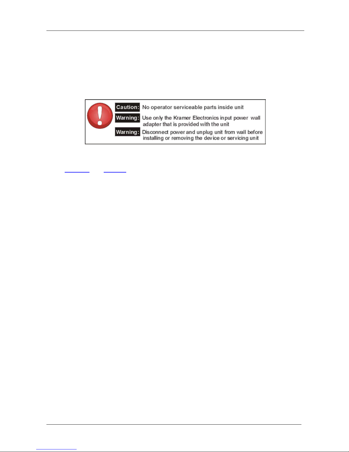
CAUTION!
Kramer Electronics (hereafter ) warrants this product free from defects in material and wor kma nship unde r the
following terms.
Kramer
HOW LONG IS THE W ARRANTY
Labor and parts are warranted for seven years from the date of the first customer purchase.
Only the first purchase customer may enforce this warranty.
W e will p ay labor and ma teria l expen ses for cover ed item s. W e wi ll not pa y for th e fol lowing:
The li abil ity of Krame r for any effe ct ive pr oduc ts is l imi ted t o the repair or re pla ceme nt of the pro duc t at ou r op tion. Kra mer sha ll
not be liabl e for:
This wa rran ty give s you spec ific l egal rights , and yo u may al so have other r ights, w hich va ry fr om place to place.
All produ cts ret urned t o Krame r for service must hav e pri or approv al. This ma y be obt ained f rom you r deal er.
This e quipm ent has b een tes ted to determi ne co mpliance with t he requ ireme nts of:
EN-50 081: "Electro magnet ic com patibili ty (EM C);
generic emission standard.
Residen tial, co mmer cial an d light industr y"
EN-50 082: "Electro magnet ic com patibili ty (EM C) gen eric im munity stand ard.
Part 1 : Reside ntia l, comm ercial and lig ht indus try e nviro nment".
CFR-47: FCC* Rules and Regulations:
Part 15 : “Ra d io frequency devices
Subpart B Unintentional radiators”
Except as below, this warranty covers all defects in material or workmanship in this product. The following are not covered
by the warranty:
1. Any product which is not distributed by Kramer, or which is not purchased from an authorized Kramer dealer. If you are
uncertain as to whether a dealer is authorized, please contact Kramer at one of the agents listed in the Web site
www.kramerelectronics.com.
2. Any product, on which the serial number has been defaced, modified or removed, or on which the WARRANTY VOID
TAMPER E D sti c ke r ha s be en to r n,
3. Damage, deteri oratio n or ma lfuncti on resu lting from:
i) Accident, misuse, abuse, neglect, fire, water , lightn ing o r other acts of na ture
ii) Produc t modi ficati on, or fa ilur e to foll ow instr ucti ons sup plied w ith the produ ct
iii) Rep air o r attemp ted re pair by a nyone n ot auth oriz ed by Kra mer
iv) Any ship ment o f the pr oduct ( claim s must b e presen ted to the carr ier)
v) Remova l or i nstalla tion of the pro duct
vi) Any other cause, which does not relate to a product defect
vii)Cartons, e quipme nt encl osure s, cabl es or accesso ries use d in c onjunc tion wi th the p roduct
1. Remova l or inst alla tions c harge s.
2. Costs of initial technical adjustments (set-up), including adjustment of user controls or programming. These costs are the
respon sibi lity of the Kra mer deal er fr om whom t he produ ct wa s purcha sed.
3. Shi pping c harge s.
1. To obtain service on you product, you must take or ship it prepaid to any authorized Kramer service center.
2. Whenever warranty service is required, the original dated invoice (or a copy) must be presented as proof of warranty
coverage, and should be included in any shipment of the product. Please also include in any mailing a contact name,
company, address, and a description of the problem(s).
3. For the name of the nearest Kramer authorized service center, consult your authorized dealer.
All implied warranties, including warranties of merchantability and fitness for a particular purpose, are limited in duration to
the length of this warranty.
1. Dam age to o ther pr operty c aused b y defect s in th is prod uct, dam ages ba sed upo n inconve nien ce, loss of use o f the pro duct, l oss
of time, commercial lo ss; o r:
2. An y ot her d ama ges , whe the r inc ide nta l, c onseq uen ti al or oth erwi se. Som e co untr ies may not all ow li mit ati ons o n how l ong an
implied warranty lasts and/or do not allow the exclusion or limitation of incidental or consequential damages, so the above
limit ation s and exc lusio ns may no t apply to yo u.
Servicing the machines can only be done by an authorized Kramer technician. Any user who makes changes or
modifications to the unit without the expressed approval of the manufacturer will void user authority to operate the
equipment.
Use th e suppl ied DC p ower sup ply t o feed p ower to t he mach ine.
Please use recommended interconnection cables to connect the machine to other components.
IF reattached, removed or otherwise interfered with.
* FCC and CE appro ved usin g STP cable ( for twist ed pai r products )
NOTE:
Part 1 :
Page 19

Kramer Electronics, Ltd.
Web site: www.kramerelectronics.com
E-mail: info@kramerel. com
P/N: 2900-000636 REV 1
For the latest information on our products and a list of Kramer
distributors, visit our Web site: www.kramerelectronics.com,
where updates to this user manual may be found.
We welcome your questions, commen ts and feedba ck .
Caution
Safety Warning:
Disconnect the unit from the power supply before
opening/servicing.
 Loading...