

Kramer VP-733 Quick Start Manual
VP-733 Quick Start (P/N: 2900-300547QS REV 1)
P/N:
2 9 0 0 - 3 0 0 5 4 7 QS
Rev:
1
Scan for full manual
VP-733 Quick Start Guide
This guide helps you install and use your VP-733 for the first time.
Go to www.kramerav.com/downloads/VP-733 to download the latest user manual and check if firmware
upgrades are available.
Step 1: Check what’s in the box
VP-733 Presentation Switcher/Dual Scaler
1 Set of rack ears
4 Rubber feet
IR remote control transmitter with batteries
1 Power cord
1 Quick start guide
2 15-pin HD (M) to 3 RCA (F) breakout cables (C-GM/3RVF-1)
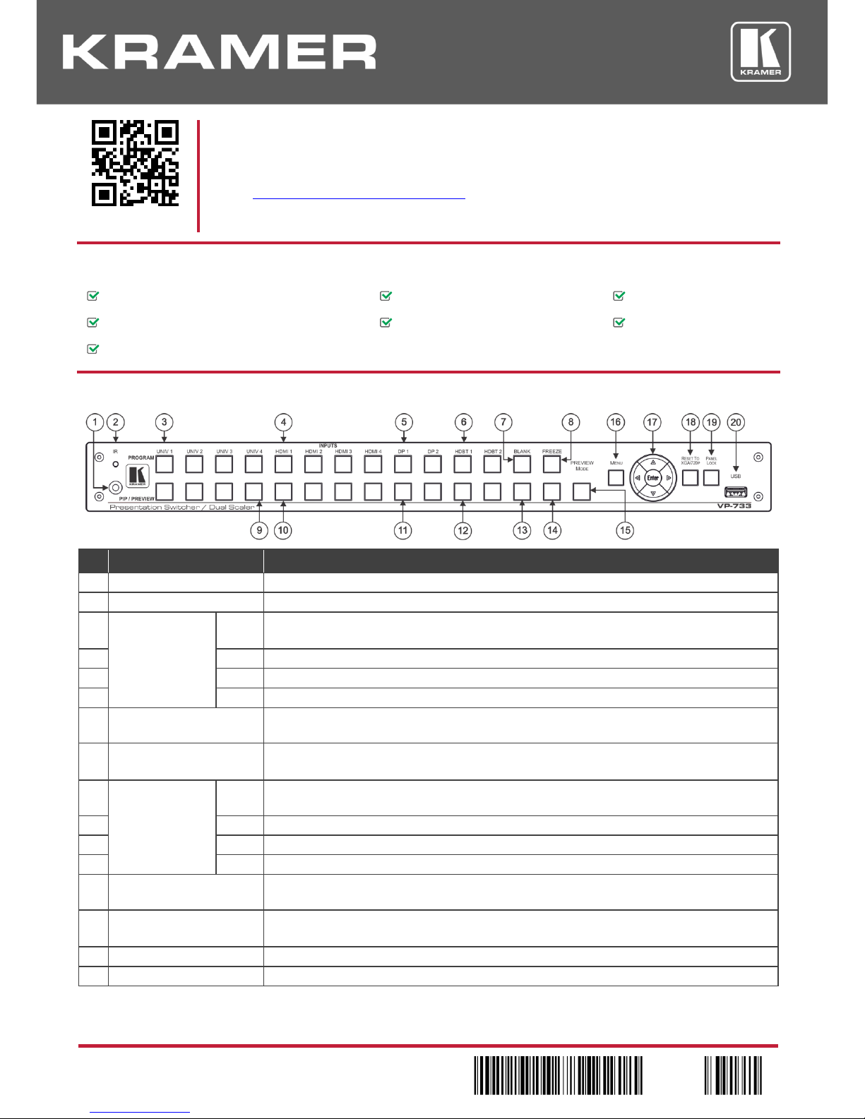
Step 2: Get to know your VP-733
#
Feature
Function
1
IR Receiver
Receives signals from the remote control transmitter.
2
LED
Lights red when the unit accepts IR remote commands.
3
PROGRAM
INPUT Selector
Buttons
(Illuminated green
when selected)
UNIV
Press to select the computer graphics/composite video / s-Video / component video source.
The video source type is configured via the OSD menu (from 1 to 4).
4
HDMI
Press to select the HDMI source (from 1 to 4).
5
DP
Press to select the DP source (from 1 to 2).
6
HDBT
Press to select the HDBT source (from 1 to 2).
7
Program BLANK Button
Press to toggle between a blank screen (blue or black) and the program display.
The BLANK button can be programmed to mute the audio signal when the blank screen is toggled.
8
Program FREEZE Button
Press to freeze/unfreeze the program output video image.
The FREEZE button can be programmed to mute the audio signal when the image is frozen.
9
PIP / PREVIEW
INPUT Selector
Buttons
(Illuminated yellow
when selected)
UNIV
Press to select the computer graphics/composite video / s-Video / component video source; the
video source type is configured via the OSD menu (from 1 to 4).
10
HDMI
Press to select the HDMI source (from 1 to 4).
11
DP
Press to select the DP source (from 1 to 2)...
12
HDBT
Press to select the HDBT source (from 1 to 2)
13
Preview BLANK Button
Press to toggle between a blank screen (blue or black) and the preview display.
The BLANK button can be programmed to mute the audio signal when the blank screen is toggled.
14
Preview FREEZE Button
Press to freeze/unfreeze the preview output video image.
The FREEZE button can be programmed to mute the audio signal when the image is frozen.
15
PREVIEW MODE Button
Press to toggle between PIP and Preview Mode operation.
16
MENU Button
Press to display the OSD menu on screen. Press again to return to normal operation.
#
Feature
Function
17
ENTER Button
Press to move to the next level in the OSD menu or to accept a new parameter.
Button
Decreases the range by one step in the OSD menu or moves to the previous level in the OSD.
Decreases the volume level when not in the OSD menu.
Button
Moves up one step (in the same level) in the OSD menu
Moves to the previous slide when running a slideshow.
Button
Increases the range by one step in the OSD menu.
Increases the volume level when not in the OSD menu.
Button
Moves down one step (in the same level) in the OSD menu.
Moves to the next slide when running a slideshow.
18
RESET TO XGA/720p
Button
Press and hold to reset to the default resolution (toggles between RESET TO XGA and 720p).
19
PANEL LOCK Button
Press and hold to lock/unlock the front panel buttons to prevent unintentional operation.
20
USB Connector
Connects to a USB drive to download a logo and save settings.
#
Feature
Function
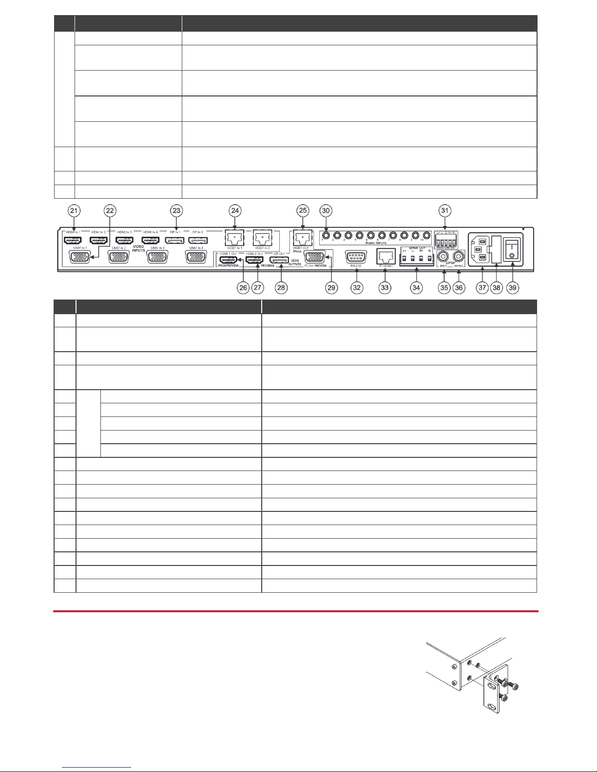
21
HDMI IN 1 Connector
Connect to an HDMI source (from 1 to 4).
22
UNIV IN 1 15-pin HD Connector
Connect to a computer graphics/composite video/s-Video (Y/C)/component
video source (from 1 to 4).
23
DP IN 1 DisplayPort Connector
Connect to a DP source (from 1 to 2).
24
HDBT IN 1 Connector
Connect to an HDBT transmitter (for example, the Kramer TP-580Txr) to
pass audio and video signals as well as serial commands (from 1 to 2).
25
VIDEO
OUTPUTS
PROG HDBT OUT Connector
Connect to an HDBT receiver (for example, the Kramer TP -580Rxr).
26
PROG/PREVIEW HDMI 1 OUT Connector
Connect to an HDMI acceptor (selectable PREVIEW or PROGRAM).
27
PROGRAM HDMI 2 OUT Connector
Connect to an HDMI acceptor.
28
PROGRAM DP OUT Connector
Connect to a DP acceptor.
29
PREVIEW PC OUT 15-pin HD Connector
Connect to a computer graphics acceptor.
30
AUDIO INPUTS 3.5 Mini Jack Connectors
Connect to the unbalanced stereo analog audio sources from 1 to 10.
31
AUDIO LINE OUT 5-pin Terminal Block
Connect to a balanced stereo analog audio acceptor.
32
RS-232 9-pin D-sub Connector
Connect to a PC or serial controller.
33
ETHERNET Port
Connect to your Local Area Network.
34
SPKR OUT 4-pin Terminal Block
Connect to a pair of loudspeakers.
35
S/PDIF INPUT 3.5 Mini Jack Connector
Connect to a digital audio source.
36
S/PDIF OUTPUT 3.5 Mini Jack Connector
Connect to a digital audio acceptor.
37
Mains Power Connector
Connect to the mains power.
38
Mains Power Fuse
Fuse for protecting the device.
39
Mains Power Switch
Switch for turning the unit ON or OFF.
Step 3: Install VP-733
Install VP-733 using one of the following methods:
Remove the three screws from each side of the unit, reinsert those screws through the
rack ears and mount on a 19" rack.
Attach the rubber feet and place the unit on a flat surface.
 Loading...