


Kramer Electronics, Ltd.
USER MANUAL
Model:
VP-730
Presentation Switcher / Scaler

Contents
i
Contents
1 Introduction 1
2 Getting Started 1
2.1 Quick Start 1
3 Overview 3
3.1 About HDMI 5
3.2 Recommendations for Best Performance 6
4 Your Presentation Switcher / Scaler 6
5 Installing in a Rack 10
6 Connecting Your VP-730 Presentation Switcher / Scaler 11
6.1 Connecting a PC 13
6.2 Connecting the Balanced/Unbalanced Stereo Audio Input/Output 14
6.3 Connecting the Digital S/PDIF Audio Input 15
7 Presentation Switcher / Scaler Buttons 15
7.1 Switching an Input 15
7.2 The PIP Button Feature 15
7.2.1 Activating the P IP Feature 16
7.2.2 Selecting the PIP Source 16
7.2.3 Toggling between the PIP and the Screen Source (Swap) 17
7.2.4 Quick Selection of the PIP Source via the Front Panel Buttons 18
7.3 Locking and Unlocking the Front Panel 20
7.4 The Infrared Remote Control Transmitter 20
8 Configuring the VP-730 via the OSD MENU Screens 22
8.1 The Input Screen 23
8.2 The Picture Screen 24
8.3 The Output Screen 25
8.4 The PIP Screen 27
8.5 The Audio Screen 28
8.6 The Geometry Screen 29
8.7 The Setup Screen 30
8.7.1 The Slideshow Feature 31
8.7.2 The Advanced Setup Screen 32
8.8 Verifying Configuration Detai ls via the Info S creen 35
9 Using Text Overlay 36
10 Audio Flash Memory Upgrade 38
10.1 Downloading from the Internet 39
10.2 Connecting the PC to the RS-232 Port 39
10.3 Upgrading the Audio Firmware 40
11 Technical Specifications 44
12 VP-730 Communication Protocol 49
12.1 Error Codes Description 60

KRAMER: SIMPLE CREATIVE TECHNOLOGY
Contents
ii
Figures
Figure 1: VP-730 Presentati on Switcher / Scaler Front Panel 7
Figure 2: VP-730 Presentati on Switcher / Scaler Rear Panel 7
Figure 3: Connecting the VP-730 Rear Panel 12
Figure 4: Connecting the PC 13
Figure 5: Connecting the Balanced Stereo Audio Input/Output 14
Figure 6: Connecting the Unbalanced Stereo Audio Input 14
Figure 7: Connecting the Unbalanced Stereo Audio Output 14
Figure 8: Connecting the Digital S/PDIF Audio Input 15
Figure 9: PIP Source Over Background 17
Figure 1 0: OSD SWAP Status 17
Figure 11: Remote Transmitter 21
Figure 1 2: MENU Items 22
Figure 1 3: Input Screen 23
Figure 1 4: Picture Screen 24
Figure 1 5: Output Screen 25
Figure 1 6: PIP Screen 27
Figure 1 7: Audio Screen 28
Figure 1 8: Geometry Screen 29
Figure 1 9: Setup Screen 30
Figure 20: Advanced Setup Screen 32
Figure 2 1: Misc Setup Screen 33
Figure 2 2: Information Scr een 36
Figure 23: TextOverlay Applicatio n Screen 37
Figure 2 4: RS-232 PINOUT Conne c t ion 39
Figure 2 5: Splash Screen 40
Figure 26: Atmel – Flip Window 40
Figure 27: Device Selection Window 41
Figure 28: Selecting the Device Window 41
Figure 29: Loading the Hex 42
Figure 3 0: RS-232 Window 42
Figure 31: Atmel – Flip Window (Connected) 43
Figure 32: Atmel – Flip Window (Operation Completed) 43
Tables
Table 1: Front Panel VP-730 Presentation Switcher / Scaler Features 8
Table 2: Rear Panel VP-730 Presentation Switcher / Scaler Features 9
Table 3: PIP Source Appearance Availability 19
Table 4: Infrared Remote Control Transmitter Functions 21
Table 5: Input Screen Functions 23
Table 6: Picture Screen Functions 24
Table 7: Output Screen Functions 25
Table 8: PIP Screen Functions 27
Table 9: Audio Screen Functions 28
Table 10: Geometry Screen Functions 29
Table 11: Available Settings for Each Application 30

Contents
iii
Table 12: Setup Screen Functions 30
Table 13: Mode Set Functions 32
Table 14: OSD Functions 32
Table 15: Misc Functions 33
Table 16: Input Functions 34
Table 17: Output Functions 35
Table 18: Features and Functions of the TextOverlay Application 37
Table 19: RS-232 PINOUT Connecti on 39
Table 20: Technical Specifications of the VP-730 Present ation Switchers / Scaler 44
Table 21: Technical Specifications of the RGBHV / RGBS (PC) / RGsB (PC) Input Signal 45
Table 22: Technical S pecifications of the HDMI Input Signal (for RGB Colorspace) 45
Table 23: Technical Specifications of the Y/C, Video Signal 46
Table 24: Technical S pecifications of the HDMI Input Signal (for RGB or YUV Color space) 46
Table 25: Technical Spec ifications of the Compone nt Input Sig nal 46
Table 26: Technical Specifications of the RGBHV/Comp/YPbPr Output Signal 47
Table 27: Technical S pecifications of the HDMI /RGB Output S ignal 48

Introduction
1 1
1 Introduction
Welcome to Kramer Electronics! Since 1981, Kramer Electronics has been
providing a world of uni que, creat iv e, an d aff ordabl e s olutions to the vast range
of problems that confr ont th e video, audio, presentation, and broadcas t ing
professional on a daily basis. In recent years, we have redesigned and upgraded
most of our line, making th e best ev en be tter! Our 1, 000-plus different models
now appear in 11 grou ps
1
Congratulations on purchasing your Kramer VP-730 Presentation Switcher /
Scaler, which is ideal for the following typical applications:
that are clearly defined by function.
• Projection systems in conference rooms, boardrooms, auditoriums, hotels and
houses of worship
• Production studios, rental and staging and where high quality conversion and
switching of multiple and different video signals to graphical data signals is
required for projection purposes
The package includes the following items:
• VP-730 Presentation Switcher / Scaler
• Infrared remote control transmitter
• Power cord
2
• This user manual
and null-modem adapter
3
2 Getting Started
We recommend that you:
• Unpack the equipment carefully and save the original box and packaging
materials for possible future shipment
• Review the conten ts of this use r m anual
• Use Kramer high performance high resolution cables
4
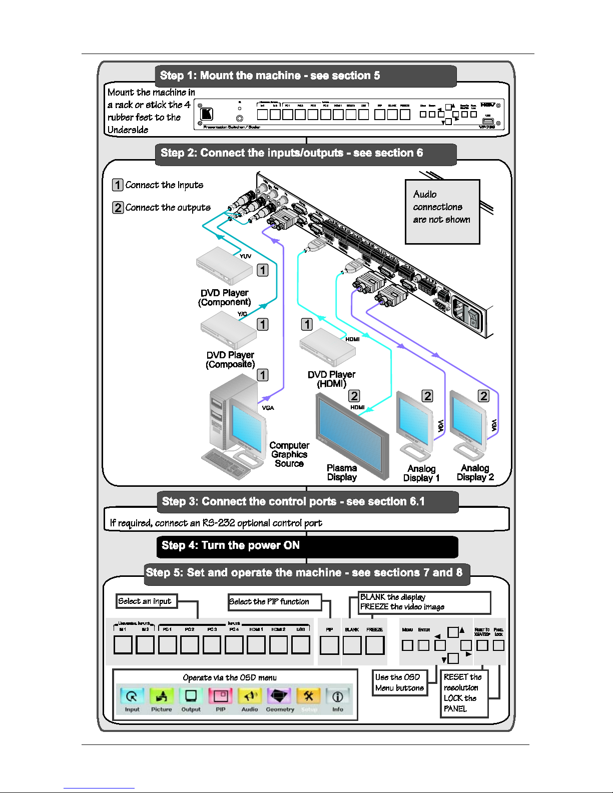
2.1 Quick Start
The quick start charts summarize the basic setup and operation steps of the
VP-730.
1 GROUP 1: Distribution Amplifiers; GROUP 2: Switchers and Matrix Switchers; GROUP 3: Control Syste ms; GROUP 4:
Format/Standards Converters; GROUP 5: Range Extenders and Repeaters; GROUP 6: Specialty AV Products; GROUP 7:
Scan Converters and Scalers; GROUP 8: Cables and Connectors; GROUP 9: Roo m Connectivity; GROUP 10: Accessories
and Rack Adapters; GROUP 11: Sierra Products
2 We recommend that you use only the power cord that is supplied with this machine
3 Download up-to-date Kramer user manuals from our Web site at http://www.kramerelectronics.com
4 The complete list of Kramer cables is on our Web site at http://www.kramerelectronics.com
KRAMER: SIMPLE CREATIVE TECHNOLOGY
Getting Started
2

Overview
3 3
3 Overview
The Kramer VP-730 is a 9-input Proscale™ Presentation Switcher / Scaler.
Each audio input can accept balanced stereo audio or digital S/PDIF audio.
The VP-730 has a balanced stereo audio output and a digital S/PDIF a udio
output.
The VP-730 scales any composite, s-Video (Y/C), component video (YPbPr),
HDMI or computer graphics video signal, as well as jpeg files (via USB) up
or down to a selectable graphics or HDTV output resolution and provides
glitch-free switching between sources through FTB™ (fade-thru-black)
switching technolog y. The out put signal is avail able simultaneously on two
15-pin HD computer graphics video (PC) connectors and on a n HDMI
connector.
The VP-730 features include:
• Silicon Optix HQV® Video Processing - HQV (Hollywood Quality Video)
processing represents the state-of-the-art in video processing technology, with
the highest quality de-interlacing, noise reduction, and scaling performance for
both standard-definition and high-definition signals
• Fade-Thru-Black (FTB™) Switching - the video fades to black and then the
new input fades from black for glitch-free and smooth switching. The output
signal provides constant sync so the display never glitches
• K-IIT XL™ Picture-in-Picture Image Insertion Technology - ultra stable
picture-in-pictur e, picture-and-picture, and split screen capability. A video
source can be inserted into or positioned next to a computer graphics video
source or vice versa with window positioning and sizing controls
• Two user definable (universal) video inputs (each can be set as composite video,
s-Video (Y/C) or component video), four computer graphics video inputs (each
can be set as RGBHV or YPbPr), two HDM I inputs and 1 USB input (for
reading JPEG picture files
1
• HDTV compatible component in put
)
• HDTV ou tpu t res olu ti ons - 480p, 576p, 720p, 1080i, and 1080p
• Scaled video outputs - HD MI and computer graphics video
• HDMI supports up to 2.25Gbps ba n dwidth per graphi c ch annel
2
• Multi ple com pute r gr aph ics outpu t re solu ti ons - including a user-defined output
resoluti on wi th sele ctable refresh rates
• Multiple aspect ratio selections
• Companion AFV (audio-follow-video) for every analog video input - supports
1 JPEG files in EXIF format are recognized, up to 1920x1200
2 Suitable for resolutions up to UXGA at 60Hz, and for all HD resolutions

KRAMER: SIMPLE CREATIVE TECHNOLOGY
Overview
4
embedded audio on the two HDMI inputs and output
• Built-in noise reduction and picture enhancement featu res
• Audio inputs – selectable S/PDIF or balanced audio input for each of the two
universal video inputs, for each of the four PC video inputs on 5-pin terminal
blocks; and emb edd ed au di o on th e two HDMI inputs
• Audio outputs - S/PDIF (RCA connector) and balanced stereo audio (5-pin
terminal block). Transcodes stereo or S/PDIF audio to both stereo and S/PDIF
audio and embeds audio onto the HDMI output
• Built-in Time Base Correct or - stabilizes video sources with unstable sync
• Built-in video Proc-Amp - color, hue, sharpness, contrast, and brightness are set
individually for each input
• A BLANK button, a FREEZE button, a RESET TO XGA/720P button (to
hardware-reset the output resolution); and a PANEL LOCK button
1
• Built-in audio Proc-Amp - with bass, treble, balance and loudness control, as
well as au dio del ay
• Supports firmware upgrade
2
• Firmw are upg ra de for audio via the designated 3-pin RS-232 AUDIO PROG.
connector
via the USB port
• A slideshow feature, letting you run a slideshow via the USB port
• A user-friendly OSD (On -Screen Dis play ) that can be centered on the screen or
in one of the four corners
In addition, the VP-730:
• Includes non-volatile memo ry that ret ains th e l ast se ttings , af ter sw itch ing th e
power off and then on again
• Digitally repr ocesses the s ig nal to co rrec t m aste ri ng e rr ors, an d r egen er ates th e
video at the appropriate higher (or lower) line and pixel rate format, providing
native-res olu tion vid eo f or LC D, DL P an d pla sm a dis play s
• Is specifically designed to improve video quality by reducing chroma noise
• Includes numerous filters and algorithms for eliminat ing picture artifacts
• Scales and zooms (to up to 400% of the original size)
• Can pr ovid e non -linear scaling for 4:3, 16:9 transformation
Control yo ur VP-730 directly via the front p a nel push buttons, or:
• By RS-232 serial commands transmitted by a touch screen system, PC, or other
serial controlle r
• Remotely, from th e infrared remot e control transm itter (with on-screen menus)
1 The front panel blank, freeze and lock buttons can be programmed via the OSD menu (see Table 15)
2 To check if firmware upgrades are available, go to our Web site at
http://www.kramerelectronics.com

Overview
5 5
The VP-730 is housed in a 19” 1U rack mountable enclosure, with rack “ears”
included, and is fed from a 100-240 VAC universal sw itching power supply.
3.1 About HDMI
High-Definition Multimedia Interface (HDMI) is an uncompressed all-digital
1
In particular, HDMI
audio/video interface, widely supported in the entertainment and home cinema
industry. It delivers the maximum high-definition image and sound quality in us e
today . Not e th at Kr am er El ect ron ics L imit e d is an H DMI Ad opte r an d an HDC P
Licensee.
2
• Provides a simple
:
3
interface between any audio/video source, such as a set-top
box, DVD player, or A/V receiver and video monitor, such as a digital flat LCD
/ plasma television (DTV), over a single lengthy
4
• Supports standard, enhanced, high-definition video, and multi-channel digital
audio
cable
5
• Transmits all A TSC HDTV standards and supports 8-channel digital audio,
with bandwidth to spare to accommodate future enhancements and
requirements
on a single cable
• Benefits consumers by providing superior, uncompressed digital video quality
via a single cable
6
• Is backward-compatible with DVI (Digi tal Visua l Interface)
, and user-friendly connector
• Supports two-way commu nicatio n betw een th e vide o source (s uch as a DVD
player) and the digital television, enabling new functionality such as automatic
configuration and one-button play
• Has the capacity to support existing high-definition video formats (720p, 1080i,
and 1080p/60), standard definition formats such as NTSC or PAL, as well as
480p and 576p
1 Ensuring an all-digital rendering of video without the losses associated with analog interfaces and their unnecessary digitalto-analog conversions
2 HDMI, the HDMI logo and High-Definition Multimedia Interface are trademarks or registered trademarks of HDMI
licensing LLC
3 With video and multi-channel audio combined into a single cable, the cost, co mplexity, and confusion of multiple cables
currently used in A/V systems is reduced
4 HDMI technology has been designed to use standard copper cable construction at up to 15m
5 HDMI supports multiple audio formats, from standard stereo to multi-channel surround-sound. HDMI has the capacity to
support Dolby 5.1 audio and high-resolution audio formats
6 HDM I provides the quality and functionality of a digital interface while also supporting uncompressed video formats in a
simple, cost-effective manner

KRAMER: SIMPLE CREATIVE TECHNOLOGY
Your Presentation Switcher / Scaler
6
3.2 Recommendations for Best Perfor m ance
To achieve the best performance:
• Connect only good quality connection cables, thus avoiding interference,
deterioration in signal quality due to poor matching, and elevated noise-levels
(often asso ciated with low quality c ables)
• Avoid interference from neighboring electrical appliances and position your
Kramer VP-730 aw ay from moisture, excessive sunlight and dust
4 Your Presentation Switcher / Scaler
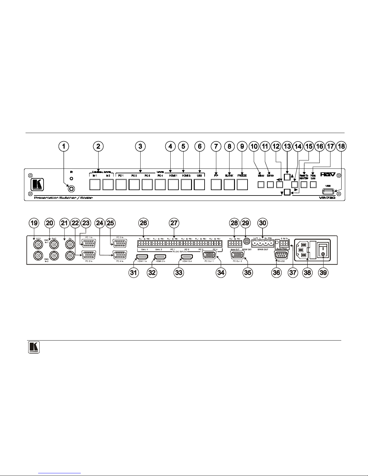
Figure 1
and Table 1 define the front pa nel of the VP-730; Figure 2 and Table
2 define the rear panel.
Your Presentation S wit cher / Scaler
7
Figure 1: VP-730 Presentation Switcher / Scaler Front Panel
Figure 2: VP-730 Presentation Switcher / Scaler Rear Panel
KRAMER: SIMPLE CREATIVE TECHNOLOGY
Your Presentation Switcher / Scaler
8
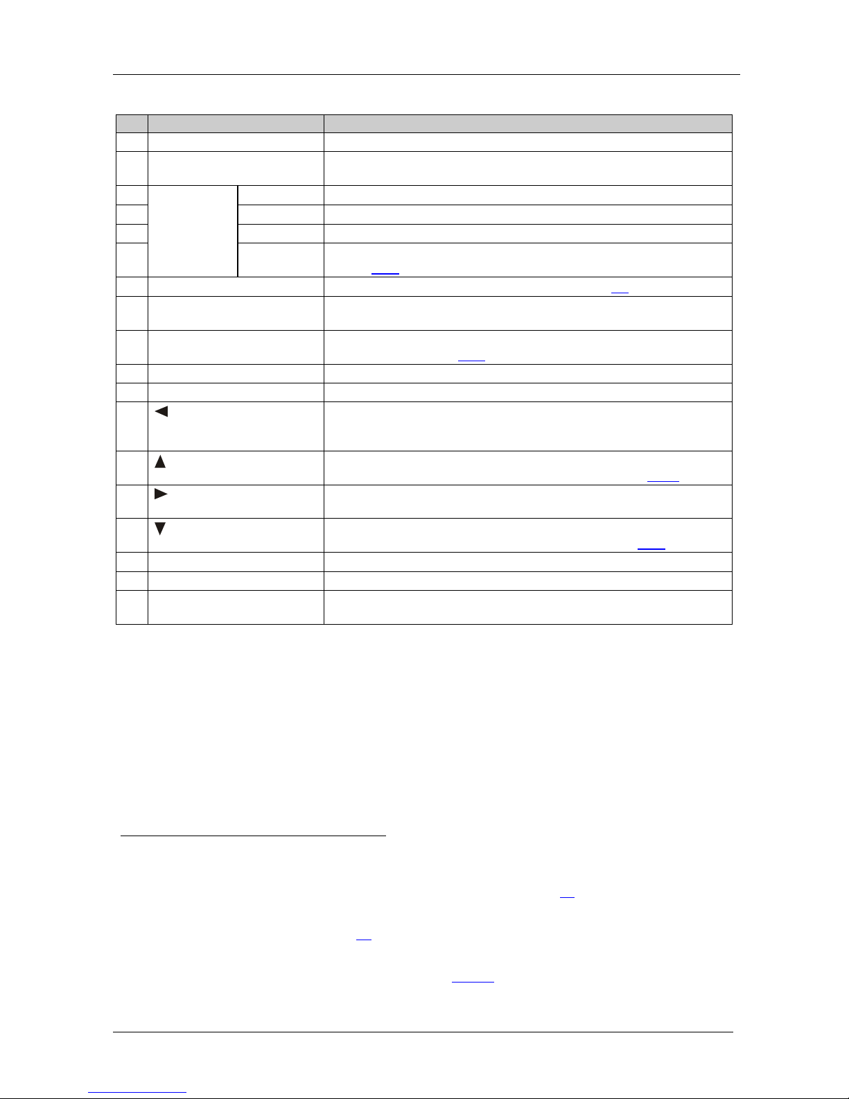
Table 1: Front Panel VP-730 Presentation Switcher / Scaler Features
#
Feature
Function
1 IR Receiver / LED Red when the unit accepts IR remote commands
2 UNIVERSAL INPUT
1
Press to select the composite video / s-Video / component video
source
Selector Buttons
2
3
(from 1 to 2)
INPUT Selector
Buttons
3
PC
1
Press to select the computer graphics2 source (from 1 to 4)
4 HDMI 1 Press to select t he HDMI source 1
5 HDMI 2 Press to select t he HDMI source 2
6 USB Press to select t he USB
4
8.7.1
source and also run/stop the slideshow (see
section )
7 PIP Button Toggles the picture-in-pi ctur e fu nc t ion (see section 7.2)
8 BLANK Button Press to toggle between a blank screen (blue or black screen)
5
9
and the
display
FREEZE Button Press to freez e /u nf reeze the ou tpu t video i mage5, as well as pause the
slideshow (see section
8.7.1)
10 MENU Button Displays the OSD menu screen (toggle)
11 ENTER Button Moves to the next level in the OSD screen, or accepts a new parameter
12
Button
Decreases the range by one step in the OSD screen or moves to the
previous level in the OSD screen
Decreases the volume level, when not in the OSD menu
13
Button
Moves up one st ep (in the same level) in the OSD screen or moves to
the previous slide when running a slideshow (see section 8.7.1
)
14
Button
Increases the range by one step in the OSD screen
Increases the volume level, when not in the OSD menu
15
Button
Moves down one step (in the same level) in the OSD screen, or moves
to the next slide when running a slideshow (see section
8.7.1)
16 RESET TO XGA/720p Button Press and hold to reset to the defau lt resolution
6
17 PANEL LOCK Button Press to lock/unloc k the front panel to prevent unintentional operation
18 USB Connector Connect to a USB dr ive to rea d J PEG file s , and al so to downl oa d new
firmware
1 The front panel UNIVERSAL INPUT selector b uttons IN 1 and IN 2 are named Input 1 and Input 2, respectively, on the IR
remote control transmitter. Similarly, the front panel I
NPUT selector buttons PC 1, PC 2, PC 3 and PC 4, are named VGA 1,
VGA 2, VGA 3 and VGA 4, respectively, on the IR remote control transmitter (see section
7.4)
2 And the appropriate audio source
3 When selected, button illuminates. See section
7.1 for details of how to program the INPUT SELECTOR buttons
4 JPEG files in EXIF format on a USB memory stick
5 Can be programmed to mute the audio signal at the same time (see
Table 15)
6 Toggles between reset to XGA and reset to 720p
Your Presentation Switcher / Scaler
9 9
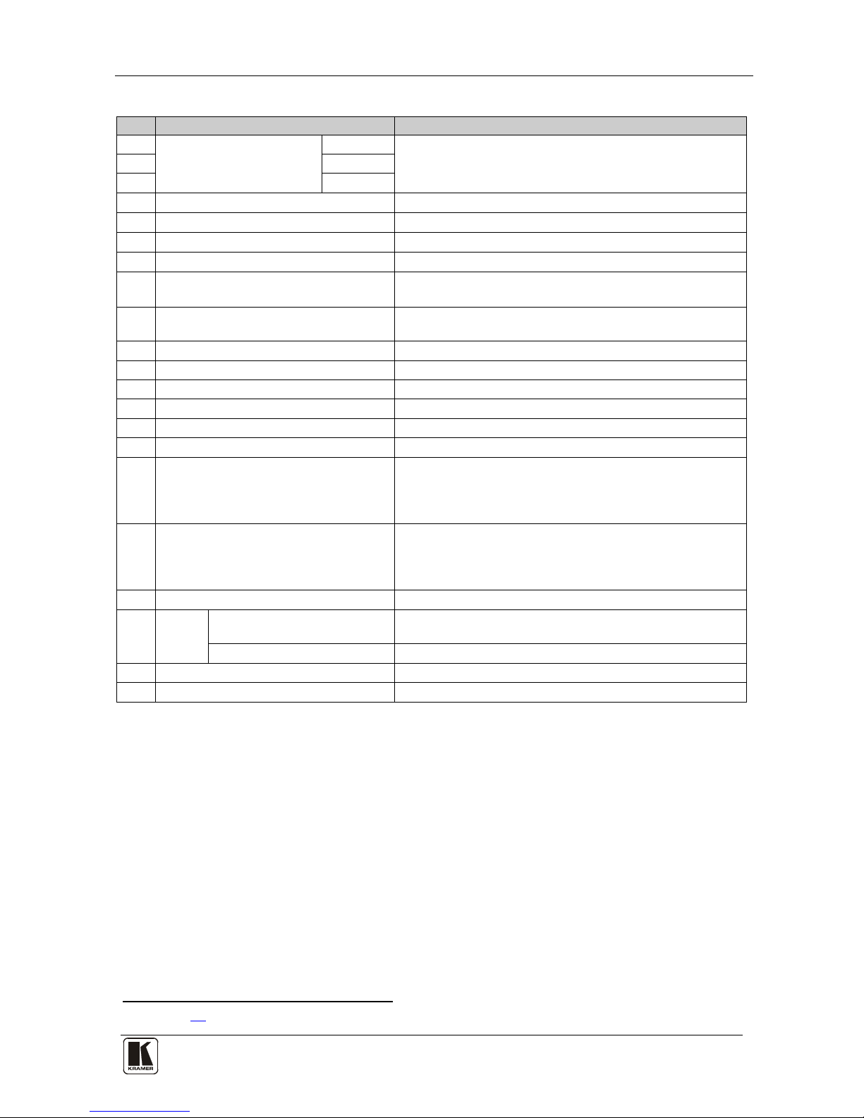
Table 2: Rear Panel VP-730 Presentation Switcher / Scaler Features
#
Feature
Function
19
UNIV. IN BNC Connectors
Y/CV
Connect to the vi de o acce pt or wh ich can be either
composite video (Y/CV), s-Video (Y/CV, P
B/C ) or
component video (Y/CV, P
B/C, PR) (from 1 to 2)
20 PB/C
21 PR
22 PC 2 IN 15-pin HD Connector Connects to t he computer grap hics source 2
23 PC 1 IN 15-pin HD Connector Connects to t he computer gr aphics source 1
24 PC 4 IN 15-pin HD Connector Connects to t he computer grap hics source 4
25 PC 3 IN 15-pin HD Connector Connects to t he computer grap hics source 3
26 UNIV. AUDIO INPUT 5-pin Terminal
Block
Connect to the balanced stereo analog or digital S/PDIF
1
27
audio sources from 1 to 2
PC AUDIO INPUT 5-pin Terminal Block Connect to the balanced stereo analog or digital S/PDIF1
audio sources from 1 to 4
28 AUDIO OUT 5-pin Terminal Bl oc k Connect to the balanced stereo analog audio acceptor
29 S/PDIF RCA Connector Connect to a digital audio source
30 SPKR OUT 4-pin Terminal Block Connect to a pair of loudsp eakers
31 HDMI 1 IN Connector Connect to the HDMI 1 source
32 HDMI 2 IN Connector Connect to the HDMI 2 source
33 HDMI OUT Connector Connect to the HDMI acceptor
34 PC OUT 1 15-pin HD Connector Connects to the video acceptor 1 that displays the scaled
output
In the default HDTV mode, the signal goes out via 3 PINS:
PIN 1 is P
R, PIN 2 is Y, PIN 3 is PB
35 PC OUT 2 15-pin HD Connector Connects to the video acceptor 2 that displays the scaled
output
In the default HDTV mode, the signal goes out via 3 PINS:
PIN 1 is P
R, PIN 2 is Y, PIN 3 is PB
36 RS-232 9-pin D-sub Connec tor Connects to PC or Serial Controller
37 AUDIO
PROG
Program Button Push to upgrade to the latest audio firmware
Release for normal operation
Terminal Block Connector C onn ect t o a PC for audio fi rmware upgrade
38 Power Connector with Fuse AC connector enabling power supply to the unit
39 POWER Switch Illuminated switch for turning the machine ON or OFF
1 See section 6.3

KRAMER: SIMPLE CREATIVE TECHNOLOGY
Installing in a R ack
10
5 Installing in a Rack
This section descr ibes what to do befor e installing in a rack and how to rack
mount.
Before Installing in a Rack
How to Rack Mount
Before installing in a rack, be sure that the environment is
within the recommended range:
To rack-mount a machine:
1. Attach both ear brackets to the
machine. To do so, remove the
screws from each side of the
machine (3 on each side), and
replace those screws through the
ear brackets.
2. Place the ears of the machine
against the rack rails, and insert the
proper screws (not provided)
through each of the four holes in the
rack ears.
Note that:
• In some models, the front panel
may feature built-in rack ears
• Detachable rack ears can be
removed for desktop use
• Always mount the machine in the
rack before you attach any cables
or connect the machine to the
power
• If you are using a Kr am er rack
adapter kit (for a machine that is not
19"), see the Rack Adapters user
manual for installation instructions
(you can download it at:
http://www.kramerelectronics.com)
Operating temperature range
+5° to +45° C (41° to 113° F)
Operating humidity range 10 to 90% RHL, non-condensing
Storage temperature range
-20° to +70° C (-4° to 158° F)
Storage humidity range 5 to 95% RHL, non-condensing
!
CAUTION
!!
When installing on a 19" rack, avoid hazards by taking
care that:
1. It is located within the recommended environmental
conditions, as the op era ti ng ambi ent t e mperature of a
closed or multi unit rack assembly may exceed the
room ambient temperature.
2. Once rack mounted, enough air will still flow around
the machine.
3. The machine is placed straight in the correct
horizontal positi on.
4. You do not overlo ad the circuit(s). When connecting
the machine to the supply circuit, overloading the
circuits might have a detrimental effect on overcurrent
protection and supply wiring. Refer to t he app ro priate
nameplate ratings for information. For example, for
fuse replacement, see the value printed on the
product label.
5. The machine is earthed (grounded) in a reliable way
and is connected onl y to an ele ctric ity socket with
grounding. Pay particular attention to situations where
electricity is supplied indirectly (when the power cord
is not plugged directly into the socket in the wall), for
example, when using an extension cable or a power
strip, and that you use only the power cord that is
supplied with the machine.

Connecting Your VP-730 Presentation Switcher / Scaler
11 11
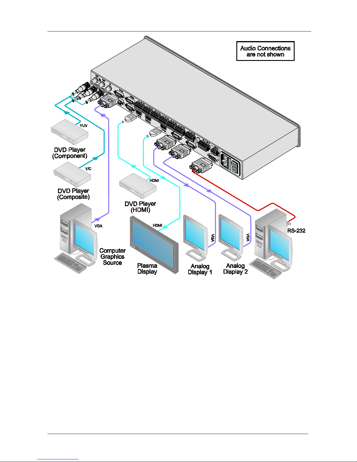
6 Connecting Your VP-730 Present ation Switcher / Scaler
To connect
1
Figure 3 the VP-730 as illustrated in the e xample in , do the
following
2
1. Connect the following video sources
:
3
A component video
:
4
A composite video source (for example, a DVD player) to the UNIV. IN
2 RCA connector Y/CV
source (for example, a DVD player) to the UNIV.
IN 1 RCA connectors, Y /CV, P
B/C and PR
A computer graphics source to the PC 1 IN 15-pin HD computer
graphics video conn ector
An HDMI source (for example, a DVD player) to the HDMI 1 IN connector
A graphics data source (for example, J P EG files from a PC or a USB
flash drive) to the USB connector on the front panel of the machine
5
2. Connect the balanced stereo audio sources
5,6
Component video source 1 to the AUDIO UNIV. IN 1 terminal block
that is, the audio of the:
Composite vide o source to the AUDIO UNIV. IN 2 terminal block
Computer graphics source to the AUDIO PC 1 terminal block
3. Connect the video output:
HDMI OUT connector to an HDMI acceptor (for example, a plasma display)
PC OUT 1 15-pin HD computer graphics video connector
7
PC OUT 2 15-pin HD computer graphics video connector
to a video
acceptor (for example, an analog display 1)
7
to a video
acceptor (for example, an analog display 2)
4. Connect
5
the AUDIO OUT 5-pin terminal block and/or the S/PDIF digital
audio output to audio acceptors.
5. Connect the SPKR OUT block connec t or to a pair of lou dspeak ers, by
connecting the left loudspeaker to the “L+” and the “L-” terminal block
connectors, and the right loudspeaker to the “R+” and the “R-” terminal
block connectors. Do not Ground the loudspeakers.
6. Connect the power cord
5,8
7. If required, connect a PC via RS-232, see section . 6.1.
1 Although this example shows only several inputs that are connected, you can connect all the inputs simultaneously
2 Switch OFF the power on each device before connecting it to your VP-730. After connecting your VP-730, switch on its
power and then switch on the power on each device
3 You do not have to connect all the inputs
4 Sometimes called YUV, or Y, B-Y, R-Y, or Y, Pb, Pr
5 Not illustrated in
Figure 3
6 As required. Not all devices need to be connected
7 In the HDTV mode, the signal goes out via three PINS: PIN 1 is Red or Pr, PIN 2 is Green or Y, PIN 3 is Blue or Pb
8 We recommend that you use only the power cord that is supplied with this machine
KRAMER: SIMPLE CREATIVE TECHNOLOGY
Connecting Your VP-7 30 Pr e s e ntation Switcher / Scaler
12
Figure 3: Connecting the VP-730 Rear Panel
Connecting Your VP-730 Presentation Switcher / Scaler
13 13
6.1 Connecting a PC
You can connect a PC (or other controller) to the VP-730 via the RS-232 port
for remote control.
To connect a PC to a VP-730 unit, using the N ull-modem adapter provided
with the machine (recommended):
• Connect the RS-232 9-pin D-sub rear panel port on the VP-730 unit to th e
Null-modem adapter and connect the Null-modem adapt er with a 9-w ire f lat
cable to the RS-232 9-pin D-sub port on your PC
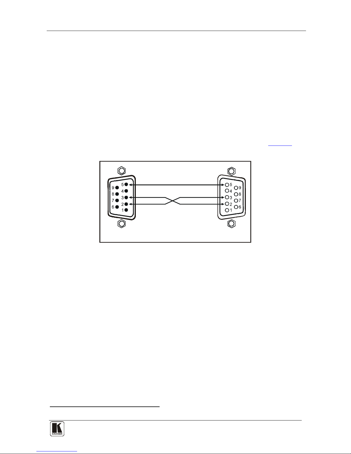
To connect a PC to a VP-730 unit, without us ing a Null-modem adapter:
• Connect the RS-232 9-pin D-sub port on your PC to the RS-232 9-pin D-sub
rear panel port on the VP-730 unit, forming a cross-connection
1
Figure 4, as
illustrates
9-pin D-sub
(From PC)
9-pin D-sub
(To Present ation
Switcher/Scaler)
If a shielded cable is used, connect the shield to PIN 5
PIN 5 Connected to PIN 5 (Ground)
PIN 3 Connected to PIN 2
PIN 2 Connected to PIN 3
Figure 4: Connecting the PC
1 Also known as a Null-modem connection
KRAMER: SIMPLE CREATIVE TECHNOLOGY
Connecting Your VP-730 Presentation Switcher / Scaler
14
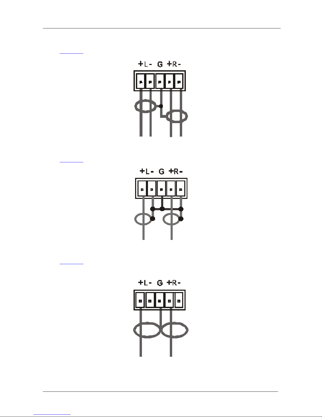
6.2 Connecting the Balanced/Unbalanced Stereo Audio Input/Output
Figure 5 illustrates how to wire a balanced input/output connection:
Figure 5: Connecting the Balanced Stereo Audio Input/Output
Figure 6 illustrates how to wire an unb a la nced input:
Figure 6: Connecting the Unbalanced Stereo Audio Input
Figure 7 illustrates how to wire an unbalanced acceptor to the balanced output
of the uni t:
Figure 7: Connecting the Unbalanced Stereo Audio Output
Presentation Switcher / Scaler Buttons
15 15
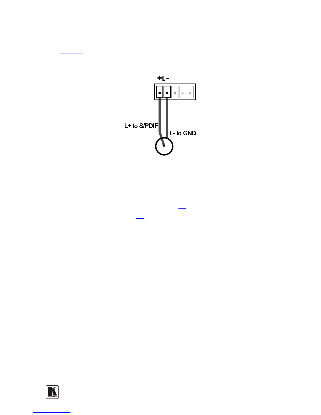
6.3 Connecting the Digital S/PDIF Audio Input
Figure 8 illustrates how to connect a d igital S/PDIF audio source to the
terminal block by wiring the first two terminal block PINs to an RCA
connector using two wires; P IN L+ to S/PDIF, and PIN L– to GND:
Figure 8: Connecting the Digital S/PDIF Audio Input
7 Presentation Switcher / Scaler Buttons
The VP-730 includes the following fron t panel buttons:
• Nine INPUT selector buttons, see section
7.1
• A PIP bu tt on, s ee se cti on
7.2
• BLANK and FREEZE buttons
• Six OSD navigation buttons
• A RESET TO XGA/720p button
• A PANEL LOCK button, see section
7.3
7.1 Switching an Input
Each INPUT SELECTOR button can be used to select the source.
You can switch seamlessly between each input that is connected to a source,
by pressing the appropriate INPUT SELECTOR button.
7.2 The PIP Button Feature
The Picture-in-Picture inserter (PIP) uses K-IIT XL™ image inse rtion
technology to present video and graphic sources simultaneously
1
1 If the HDMI signal is HDCP protected, it cannot appear on a display that is not HD CP compliant, and the machine will not
output a picture on the PC output
. You can
display:

KRAMER: SIMPLE CREATIVE TECHNOLOGY
Presentation Switcher / Scaler Buttons
16
• An inserted video source1 PIP over a graphic source
2
• An inserted graphic source
2
PIP over a video source1
Three types of PIP insertions are available:
• Picture-in-Picture – the PIP image appears over the background image
• Picture + Picture – th e video source and the graphic source are p lac ed side by
side and the aspect ratio is maintained for each image (two small im ages w ith
the correct proportions)
• Split – the video source and the graphic source are placed side by side, filling
the screen (squeezed horizontally, but not vertically)
7.2.1 Activating the PIP Feature
You can activate the PIP by:
• Pressing the PIP button
• Pressing the PIP key on the infrared remote control transmitter (see section
7.4, Figure 11)
• Switching on the PIP functionality via the OSD Menu (see
Figure 16 and
Table 8)
7.2.2 Selecting the PIP Source
To use th e P IP f eatu r e, set the PIP s ou rc e vi a th e OS D menu (see Figur e 16 and
Table 8) or the remote-transmitter keys.
To set the PIP so urce via the OSD menu, do the following:
1. Press the MENU button to enter the OSD menu.
2. Press the
button to move to the PIP icon.
3. Scroll down to select Source and press ENTER.
4. Use the
or buttons to select the PIP Source from the drop-down list
box, and press ENTER (see
Figure 16).
5. To exit the OSD menu, press the MENU button.
1 That is, composite, s-Video
2 That is, HDMI or PC or component
 Loading...