


Kramer Electronics, Ltd.
USER MANUAL
Model:
VP-727A-BA
Balanced Audio Switcher

Contents
i
Contents
1 Introduction 1
2 Getting Started 1
2.1 Quick Start 1
3 Overview 3
4 Your VP-727A-BA Balanced Audio Switcher 3
5 Installing the VP-727A-BA in a Rack 7
6 Configuring the VP-727A-BA Balanced Audio Switcher 8
6.1 Connecting the VP-727A-BA Balanced Audio Switcher 8
6.2 Connecting a PC (via RS-232) to a Standalone VP-727A-BA 10
6.3 Configuring the VP-727A-BA with the VP-727xl and the VP-727T 11
6.4 Connecting via RS-485 13
6.4.1 Connecting the VP-727A-BA to the VP-727T via the VP-727xl 13
6.4.2 Connecting the VP-727A-BA to the VP-727T via the VP-727 15
7 Flash Memory Upgrade 17
7.1 Downloading from the Internet 17
7.2 Connecting the PC to the RS-232 Port 17
7.3 Upgrading Firmware 18
8 Technical Specifications 22
9 Kramer VP-727A-BA Protocol (Ver. 3.21) 23
Figures
Figure 1: VP-727A-BA Balanced Audio Switcher 4
Figure 2: Connecting the VP-727A-BA with a VP-727xl Machine 9
Figure 3: Connecting the PC 10
Figure 4: Connecting 2 VP-727A-BA machines to the VP-727T via 2 VP-727xl Machines 11
Figure 5: Connecting the VP-727A-BA to the VP-727T via the VP-727 12
Figure 6: RS-485 Configuration between the VP-727A-BA and the VP-727xl 14
Figure 7: RS-485 Configuration between the VP-727A-BA and the VP-727 16
Figure 8: Splash Screen 18
Figure 9: Atmel – Flip Window 18
Figure 10: Device Selection Window 19
Figure 11: Selecting the Device Window 19
Figure 12: Loading the Hex 20
Figure 13: RS-232 Window 20
Figure 14: Atmel – Flip Window (Connected) 21
Figure 15: Atmel – Flip Window (Operation Completed) 21
Tables
Table 1: VP-727A-BA Balanced Audio Switcher Front Panel Features 5
Table 2: VP-727A-BA Balanced Audio Switcher Rear Panel Features 6
Table 3: Technical Specifications of the VP-727A-BA Balanced Audio Switcher 22
Table 4: Instruction Codes for the VP-727A-BA Protocol 23

Introduction
1 1
1 Introduction
Welcome to Kramer Electronics! Since 1981, Kramer Electronics has been
providing a world of unique, creative, and affordable solutions to the vast range
of problems that confront the video, audio, presentation, and broadcasting
professional on a daily basis. In recent years, we have redesigned and upgraded
most of our line, making the best even better! Our 1,000-plus different models
now appear in 11 groups
1
Congratulations on purchasing your Kramer VP-727A-BA Balanced Audio
Switcher, which is ideal for staging events, as well as:
that are clearly defined by function.
• Presentation applications that require an audio preview option
• Projection systems with sound in conference rooms, board rooms,
auditoriums, hotels, and houses of worship
The package includes these items:
• VP-727A-BA Balanced Audio Switcher
• Power cord
2
• Null-modem adapter
• This user manual
2 Getting Started
We recommend that you:
• Unpack the equipment carefully and save the original box and packaging
materials for possible future shipment
• Review the contents of this user manual
3
• Use Kramer high performance high resolution cables
4
2.1 Quick Start
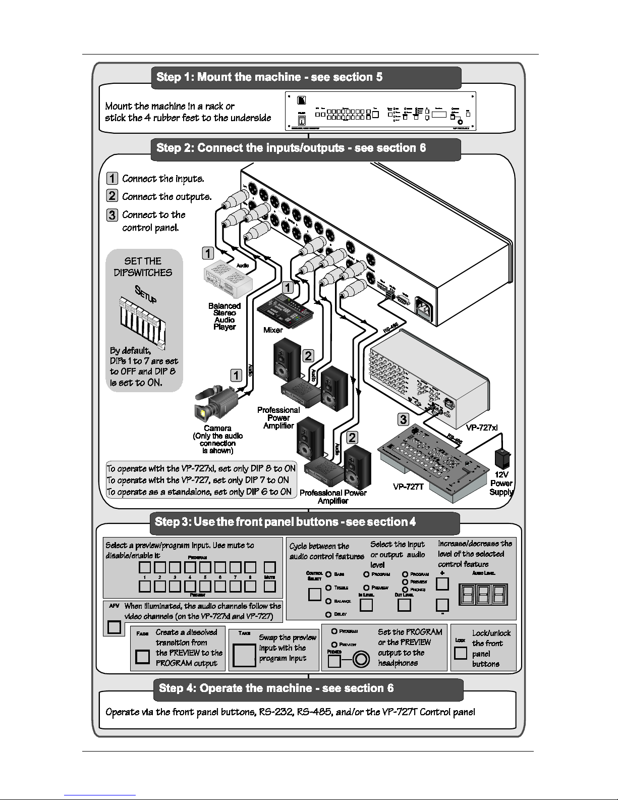
This quick start chart summarizes the basic steps when connecting a VP-727A-BA:
1 GROUP 1: Distribution Amplifiers; GROUP 2: Switchers and Matrix Switchers; GROUP 3: Control Systems; GROUP 4:
Format/Standards Converters; GROUP 5: Range Extenders and Repeaters; GROUP 6: Specialty AV Products; GROUP 7:
Scan Converters and Scalers; GROUP 8: Cables and Connectors; GROUP 9: Room Connectivity; GROUP 10: Accessories
and Rack Adapters; GROUP 11: Sierra Products
2 We recommend that you use only the power cord that is supplied with the machine
3 Download up-to-date Kramer user manuals from the Internet at this URL: http://www.kramerelectronics.com
4 The complete list of Kramer cables is on our Web site at http://www.kramerelectronics.com
KRAMER: SIMPLE CREATIVE TECHNOLOGY
Getting Started
2

Overview
3 3
3 Overview
The Kramer VP-727A-BA is a high performance 8x2 switcher for balanced
stereo audio signals. It switches any input to either the preview or program
output. The VP-727A-BA is an audio companion switcher for the VP-727xl
Universal Presentation Matrix Switcher / Scaler and the VP-727 Universal
Presentation Matrix Switcher / Scaler, and operates in conjunction with them
and the VP-727T Presentation Switcher Control Panel.
The VP-727A-BA features:
• Eight balanced stereo audio inputs on XLR F connectors
• One balanced stereo audio preview output on dual XLR M connectors
• Two balanced stereo audio program outputs on dual XLR M connectors and
a single RCA (S/PDIF) connector
• A selectable headphone connector for preview or program audio outputs
• A front panel lockout
• A TAKE button for executing preview to program switching (with
transition effects)
• An audio-follow-video button when operating in conjunction with the
VP-727xl or the VP-727
• Separate input and output level control
• Fade to mute audio switching
• Separate mute buttons for the preview and program channels
• Bass, treble and balance audio controls
• Audio delay for each input channel
The VP-727A-BA:
• Can be controlled via the front panel buttons and/or RS-232
• Is housed in a 19" 2U rack mountable enclosure
Achieving the best performance means:
• Connecting only good quality connection cables, thus avoiding interference,
deterioration in signal quality due to poor matching, and elevated noise
levels (often associated with low quality cables)
• Avoiding interference from neighboring electrical appliances, making sure
not to block the ventilation holes, and positioning your VP-727A-BA away
from moisture, excessive sunlight and dust
4 Your VP-727A-BA Balanced Audio Switcher
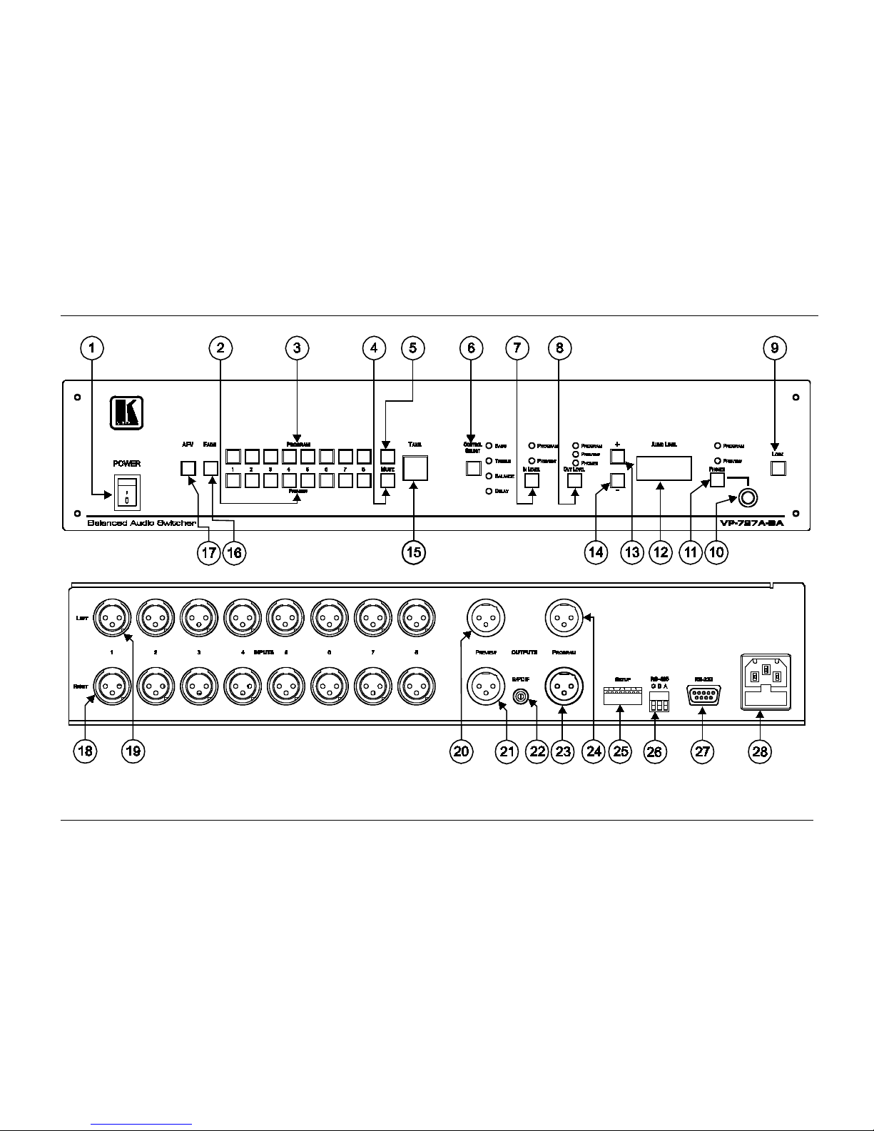
Figure 1, Table 1 and Table 2 define the VP-727A-BA:
KRAMER: SIMPLE CREATIVE TECHNOLOGY
Your VP-727A-BA Balanced Audio Switcher
4
Figure 1: VP-727A-BA Balanced Audio Switcher
Your VP-727A-BA Balanced Audio Switcher
5
Table 1: VP-727A-BA Balanced Audio Switcher Front Panel Features
#
Feature
Function
1
POWER Switch
Illuminated switch for turning the unit ON or OFF
2
PREVIEW Input Buttons
Press to select an audio source to switch to the PREVIEW output
1
3
PROGRAM Input Buttons
Press to select an audio source to switch to the PROGRAM output
1
4
MUTE
Preview Button Press to disable/enable the preview audio output
5 Program Button Press to disable/enable the program audio output
6
CONTROL SELECT Button
Press to cycle2 between the BASS, TREBLE, BALANCE and DELAY
3
7
IN LEVEL Button
Press to select
2
the PROGRAM or the PREVIEW input audio level for
each program and preview channel
8
OUT LEVEL Button
Press to select2 the PROGRAM, the PREVIEW or the PHONES output
audio level
9
LOCK Button
Press and hold to lock/unlock the front panel buttons
10
PHONES
6.3mm Jack Connect to the headphones
11 Button Press to select2 which output (PROGRAM or the PREVIEW) to send to
the headphones
12
AUDIO LEVEL 7-segment Display
Displays the numerical value of the CONTROL feature
4
13 + Button Press to increase the level4
14 - Button Press to decrease the level4
15
TAKE Button
Press to swap the preview input with the program input
5
16
FADE Button
Press to create a dissolved transition from the PREVIEW to the
PROGRAM output
17
AFV Button
When pressed, the button is illuminated, and the audio channels
follow the video channels (on the VP-727xl or the VP-727)
Deselect AFV to switch the audio channels independently
1 From 1 to 8
2 The appropriate LED lights
3 The BASS, TREBLE and BALANCE levels are set for the PROGRAM output. The DELAY is set for each PROGRAM input
4 BASS, TREBLE, BALANCE, DELAY, audio input level (PREVIEW AND PROGRAM), and audio output level
(PREVIEW AND PROGRAM)
5 To reset the VP-727A-BA to its factory default settings, turn the unit OFF, then turn it ON while pressing the TAKE button for about
2 seconds: The preview and program input is set to input 1, the input volume resets to 0dB, and the bass and treble levels reset to 0
KRAMER: SIMPLE CREATIVE TECHNOLOGY
Your VP-727A-BA Balanced Audio Switcher
6
Table 2: VP-727A-BA Balanced Audio Switcher Rear Panel Features
#
Feature
Function
18
INPUT XLR F
Connectors
RIGHT
Connect to the balanced stereo audio source (from 1 to 8)
19
LEFT
20
OUTPUTS
PREVIEW XLR
M Connectors
LEFT
Connect to a balanced stereo audio preview acceptor
21
RIGHT
22
S/PDIF RCA Connector
Connect to a digital audio acceptor
23
PROGRAM XLR
M Connectors
RIGHT
Connect to a balanced stereo audio program acceptor
24
LEFT
25
SETUP DIPs
1
DIP 8
Set to ON to operate the VP-727A-BA with the VP-727xl (as slave baud
rate 38,400); else set to OFF
DIP 7
Set to ON to operate the VP-727A-BA with the VP-727 or the VP-727T
(as chain baud rate 115,200); else set to OFF
DIP 6 Set to ON for stand alone (baud rate 9,600); else set to OFF
DIP 5 Set to ON for the fade to follow the transition effect; set to OFF for
separate fade
DIPs 3 and 4 Set to OFF (default)
DIP 2
Set to ON for RS-485 Line Termination with 120Ω; set to OFF for no
RS-485 Line Termination
DIP 1 Set to ON to upgrade to the latest Kramer firmware (see section 7); set
to OFF for normal operation (the factory default)
26 RS-485 Port
Connects to the Kramer
VP-727T
or the
VP-727xl
(see section 6.4)
Pin G is for the Ground connection
2
27
; pins B (-) and A (+) are for
RS-485
RS-232 Connector
9-pin D-sub connector connects to a PC or Remote Controller via a
null-modem connection
28 Power Connector with Fuse AC connector enabling power supply to the unit
1 By default, DIPs 1 to 7 are set to OFF and DIP 8 is set to ON
2 The ground connection is sometimes connected to the shield of the RS-485 cable. However, usually the ground is not connected
Installing the VP-727A-BA in a Rack
7
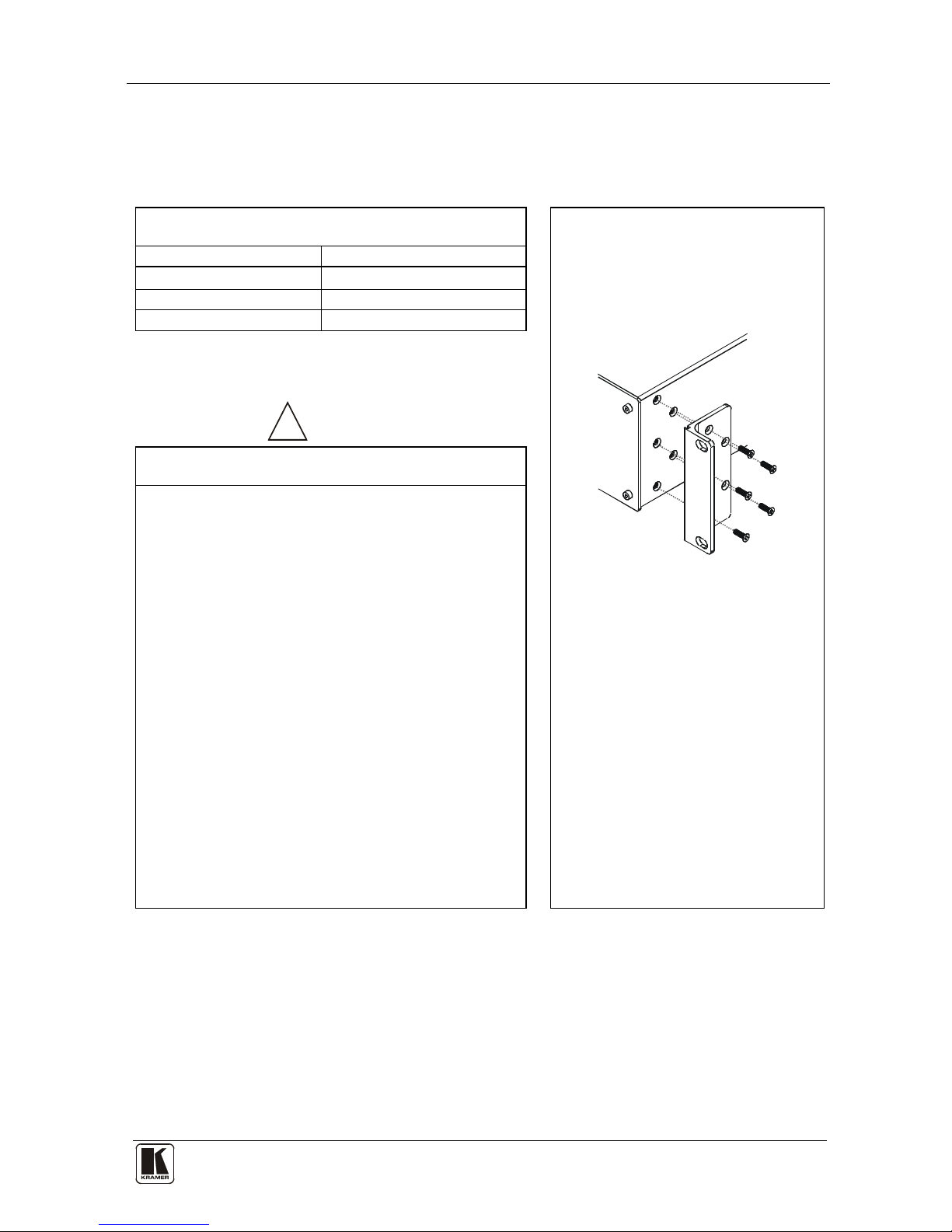
5 Installing the VP-727A-BA in a Rack
This section describes what to do before installing in a rack and how to rack
mount.
Before Installing in a Rack
How to Rack Mount
Before installing in a rack, be sure that the environment is
within the recommended range:
To rack-mount a machine:
1. Attach both ear brackets to the
machine. To do so, remove the
screws from each side of the
machine (3 on each side), and
replace those screws through the
ear brackets.
2. Place the ears of the machine
against the rack rails, and insert the
proper screws (not provided)
through each of the four holes in the
rack ears.
Note that:
• In some models, the front panel
may feature built-in rack ears
• Detachable rack ears can be
removed for desktop use
• Always mount the machine in the
rack before you attach any cables
or connect the machine to the
power
• If you are using a Kramer rack
adapter kit (for a machine that is not
19"), see the Rack Adapters user
manual for installation instructions
(you can download it at:
http://www.kramerelectronics.com)
Operating temperature range +5º to +45º C (41º to 113º F)
Operating humidity range 10 to 90% RHL, non-condensing
Storage temperature range -20º to +70º C (-4º to 158º F)
Storage humidity range 5 to 95% RHL, non-condensing
!
CAUTION
!!
When installing in a 19" rack, avoid hazards by taking
care that:
1. It is located within the recommended environmental
conditions, as the operating ambient temperature of a
closed or multi unit rack assembly may exceed the
room ambient temperature.
2. Once rack mounted, enough air will still flow around
the machine.
3. The machine is placed straight in the correct
horizontal position.
4. You do not overload the circuit(s). W hen connecting
the machine to the supply circuit, overloading the
circuits might have a detrimental effect on overcurrent
protection and supply wiring. Refer to the appropriate
nameplate ratings for information. For example, for
fuse replacement, see the value printed on the
product label.
5. The machine is earthed (grounded) in a reliable way
and is connected only to an electricity socket with
grounding. Pay particular attention to situations where
electricity is supplied indirectly (when the power cord
is not plugged directly into the socket in the wall), for
example, when using an extension cable or a power
strip, and that you use only the power cord that is
supplied with the machine.

KRAMER: SIMPLE CREATIVE TECHNOLOGY
Configuring the VP-727A-BA Balanced Audio Switcher
8
6 Configuring the VP-727A-BA Balanced Audio Switcher
This section describes how to:
• Connect the VP-727A-BA (see section 6.1)
• Connect a PC (see section 6.2)
• Configure an AV presentation switcher, with a controller (see section 6.3)
• Connect via the RS-485 (see section 6.4)
6.1 Connecting the VP-727A-BA Balanced Audio Switcher
To connect
1
Figure 2 the VP-727A-BA as the example in illustrates, do the
following
2
1. Connect the balanced audio sources to the inputs
:
3
A DVD player to the INPUT 1 LEFT and RIGHT XLR connectors
. For example, the
balanced audio signal of:
A camera to the INPUT 3 LEFT and RIGHT XLR connectors
A mixer to the INPUT 8 LEFT and RIGHT XLR connectors
2. Connect the following balanced audio outputs
4
The PREVIEW LEFT and RIGHT XLR connectors to a Preview
acceptor (for example, a professional power amplifier with speakers)
:
The PROGRAM LEFT and RIGHT XLR connectors to a Program
acceptor (for example, a professional power amplifier with speakers)
3. Connect the RS-485 terminal block connector on the VP-727A-BA to the
AUDIO CONTROL terminal block connector of the Kramer VP-727xl.
4. On the VP-727A-BA, set DIP 8 to ON
5
5. Connect the RS-485 terminal block connector on the VP-727xl (see
section
. Make sure that all the other
dipswitches are set to OFF.
6.3) to the RS-485 terminal block connector of the VP-727T.
6. Connect the power cord
6
Figure 2 (not shown in ).
1 You do not have to connect all the inputs and outputs
2 Switch OFF the power on each device before connecting it to your VP-727A-BA. After connecting your VP-727A-BA,
switch on its power and then switch on the power on each device
3 The video inputs are connected to the VP-727xl in this example. Refer to the separate user manuals for these machines,
which can be downloaded from the Internet at this URL: http://www.kramerelectronics.com
4 You can also connect the S/PDIF digital audio RCA connector and the balanced stereo audio terminal block connector to
the appropriate audio acceptors (not illustrated in Figure 2)
5 When connecting the VP-727A-BA to the VP-727, set DIP 7 to ON and make sure that all the other dipswitches are set to
OFF
6 We recommend that you use only the power cord that is supplied with this machine
 Loading...