


Kramer Electronics, Ltd.
PRELIMINARY
USER MANUAL
Models:
VP-719xl,
Presentation Switcher / Scaler
VP-720xl,
Presentation Switcher / Scaler
VP-723xl,
Presentation Switcher / Scaler
VP
-
724xl,
Presentation Switcher / Scaler

Contents
i
Contents
1
Introduction 1
2
Getting Started 1
3
Overview 2
4
Your Presentation Switcher / Scaler 4
5
Connecting your Presentation Switcher / Scaler 11
5.1
Connecting a PC 13
6
Presentation Switcher / Scaler Buttons 14
6.1
Switching an Input 14
6.2
The PIP Button Feature 15
6.2.1 Selecting the PIP Source 15
6.2.2 Activating the PIP Feature 16
6.2.3 The PIP Source (Orange) Frame 16
6.2.4 Toggling between the PIP and the Screen Source (SWAP) 17
6.2.5 PIP Characteristics 17
6.2.5.1 Resizing the PIP 18
6.2.5.2 Moving the Position of the PIP 18
6.3
Locking and Unlocking the Front Panel 19
6.4
The Infra-Red Remote Control Transmitter 19
7
Configuring the VP-724xl via the OSD MENU Screens 22
7.1
Controlling the Brightness and Contrast 23
7.2
Controlling the Gamma and Color 24
7.3
Selecting the Source 24
7.4
Controlling the Scale Geometry 25
7.4.1 Setting the Scale Features 25
7.4.2 Adjusting the Zoom Ratio and Position 26
7.4.2.1 Adjusting the Zoom Ratio 27
7.4.2.2 Adjusting the Zoom Position 28
7.5
Configuring via the Utility Screens 29
7.5.1 Choosing the Graphic Utility Settings 29
7.5.2 Choosing the Video Utility Settings 30
7.5.3 Choosing the Audio Utility Settings 31
7.5.4 Choosing the PIP Utility Settings 31
7.5.5 Choosing the Seamless Switch Utility Settings 32
7.5.6 Choosing the OSD Utility Settings 33
7.5.7 Choosing the Output Utility Settings 34
7.5.7.1 The User Mode Setting 35
7.5.8 Choosing Factory Reset 36
7.5.9 Choosing Advanced Utility Settings 36
7.6
Verifying Configuration Details via the Information Screen 37
8
Technical Specifications 38
9
VP-724xl Communication Protocol 39

KRAMER: SIMPLE CREATIVE TECHNOLOGY
Contents
ii
Figures
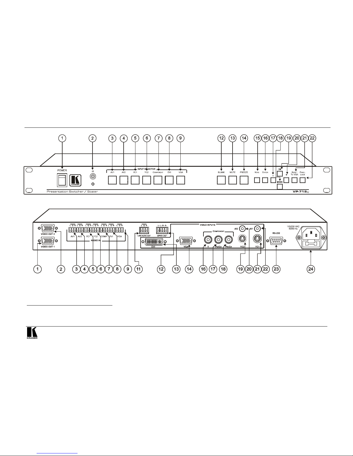
Figure 1: VP-719xl Presentation Switcher / Scaler Front Panel 5
Figure 2: VP-719xl Presentation Switcher / Scaler Rear Panel 5
Figure 3: VP-720xl Presentation Switcher / Scaler Front Panel 6
Figure 4: VP-720xl Presentation Switcher / Scaler Rear Panel 6
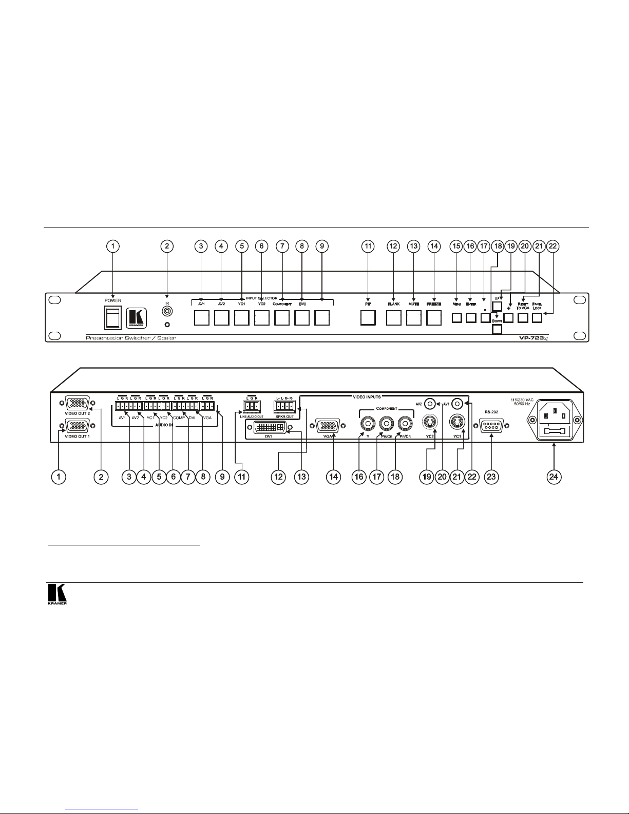
Figure 5: VP-723xl Presentation Switcher / Scaler Front Panel 7
Figure 6: VP-723xl Presentation Switcher / Scaler Rear Panel 7
Figure 7: VP-724xl Presentation Switcher / Scaler Front Panel 8
Figure 8: VP-724xl Presentation Switcher / Scaler Rear Panel 8
Figure 9: Connecting the VP-724xl Rear Panel 12
Figure 10: Connecting the PC 13
Figure 11: OSD Input Status 14
Figure 12: PIP Source 15
Figure 13: OSD SWAP Status 17
Figure 14: PIP Size – Split Screen 18
Figure 15: Moving the Position of the PIP 18
Figure 16: Infra-Red Remote Control Transmitter 20
Figure 17: MENU Screen 22
Figure 18: Menu Screen Icons 22
Figure 19: Brightness and Contrast Screen 23
Figure 20: Gamma and Color Screen 24
Figure 21: Source Selection Screen 24
Figure 22: Geometry (Scale and Zoom) Screen 25
Figure 23: Geometry (Scale: Aspect Ratio) Screen 25
Figure 24: Geometry (Zoom) Screen 26
Figure 25: OSD Enlarge Status 27
Figure 26: Geometry (Zoom Ratio) Screen 27
Figure 27: Preset Position Control Keys 28
Figure 28: Navigation Control Keys 28
Figure 29: Geometry (Zoom Position Adjustment) Screen 28
Figure 30: Utility Screen 29
Figure 31: Graphic Setting Utility Screen 29
Figure 32: Video Setting Utility Screen 30
Figure 33: Audio Setting Utility Screen 31
Figure 34: PIP Utility Screen 31
Figure 35: Seamless Switch Utility Screen 32
Figure 36: OSD Setting Utility Screen 33
Figure 37: Output Setting Utility Screen 34
Figure 38: OSD Output Status 34
Figure 39: Output Setting User Mode Setting Utility Screen 35
Figure 40: Factory Reset Utility Screen 36
Figure 41: Advanced Utility Screen 36
Figure 42: Information Screen 37

Contents
iii
Tables
Table 1: Front Panel Presentation Switcher / Scaler Features 9
Table 2: Rear Panel Presentation Switcher / Scaler Features 10
Table 3: PIP Source Appearance Availability 16
Table 4: Infra-Red Remote Control Transmitter Functions 21
Table 5: Brightness and Contrast Screen Functions 23
Table 6: Gamma and Color Screen Functions 24
Table 7: Geometry Scale Functions 26
Table 8: Geometry Zoom Functions 26
Table 9: Graphic Setting Utility Screen Features 30
Table 10: Video Setting Utility Screen Features 30
Table 11: PIP Setting Utility Screen Features 31
Table 12: Seamless Switch Utility Screen Features 32
Table 13: OSD Setting Utility Screen Features 33
Table 14: Output Setting Utility Screen Features 34
Table 15: User Mode Setting Definitions 35
Table 16: Advanced Utility Screen Features 36
Table 17: User Define Measure Features 37
Table 18: Technical Specifications of the Presentation Switchers / Scalers 38
Table 19: RS-232 Protocol 39
Table 20: RS-232 Communication Code 39
Table 21: RS-232 Read Command 41

Introduction
1
P
R
E
L
I
M
I
N
A
R
Y
1 Introduction
Welcome to Kramer Electronics (since 1981): a world of unique, creative and
affordable solutions to the infinite range of problems that confront the video,
audio and presentation professional on a daily basis. In recent years, we have
redesigned and upgraded most of our line, making the best even better! Our
350-plus different models now appear in 8 Groups1, which are clearly defined
by function. Congratulations on purchasing your Kramer VP-719xl/
VP-720xl/VP-723xl/VP-724xl Presentation Switcher / Scaler, which is ideal
for the following typical applications:
Projection systems in conference rooms, boardrooms, auditoriums, hotels and
churches
Production studios, rental and staging
Any application where high quality conversion and switching of multiple and
different video signals to graphical data signals is required for projection
purposes
The package includes the following items:
VP-719xl/VP-720xl/VP-723xl/VP-724xl Presentation Switcher / Scaler
Power cord2
Infra-red remote control transmitter
Null-modem adapter
This user manual3
2 Getting Started
We recommend that you:
Unpack the equipment carefully and save the original box and packaging
materials for possible future shipment
Review the contents of this user manual
Use Kramer high performance high resolution cables4
1 GROUP 1: Distribution Amplifiers; GROUP 2: Video and Audio Switchers, Matrix Switchers and Controllers; GROUP 3:
Video, Audio, VGA/XGA Processors; GROUP 4: Interfaces and Sync Processors; GROUP 5: Twisted Pair Interfaces;
GROUP 6: Accessories and Rack Adapters; GROUP 7: Scan Converters and Scalers; and GROUP 8: Cables and Connectors
2
We recommend that you use only the power cord that is supplied with this machine
3 Download up-to-date Kramer user manuals from our Web site at http://www.kramerelectronics.com
4 The complete list of Kramer cables is on our Web site at http://www.kramerelectronics.com

KRAMER: SIMPLE CREATIVE TECHNOLOGY
Overview
2
P
R
E
L
I
M
I
N
A
R
Y
3 Overview
The VP-719xl/VP-720xl/VP-723xl/VP-724xl is a Presentation Switcher /
Scaler designed for a wide variety of presentation and multimedia
applications. It is a true multi-standard video to RGBHV (pixel) scaler and a
seamless presentation switcher. It converts video, s-Video, component video,
VGA-through-UXGA and DVI signals to a range of user-selectable VESA
and HDTV pixel rates, as well as some other special resolutions. Using the
Presentation Switcher / Scaler, you can select any one of the inputs and scale
that input to the output at the set resolution.
The Presentation Switchers / Scalers support the following user-selectable
pixel rates:
VGA (640x480) 1024x1024i 480p
1
SVGA (800x600) 1366x768 720p
1
XGA (1024x768) 1365x1024 1080i
1
SXGA (1280x1024) 1280x720 1400x1050
UXGA (1600x1200)
720x483 1280x768*2
852x1024i 852x480 User Define
3
Each Presentation Switcher / Scaler:
Digitally reprocesses the signal to correct mastering errors, and regenerates the
video at a higher line and pixel rate format, providing native-resolution video for
LCD, DLP and Plasma displays
Up- and down-scales any graphics resolution to any other resolution
4
Incorporates a unique graphics-scaling engine with image enhancement
algorithms, which are built into the firmware
Is specifically designed to improve video quality by reducing chroma noise
Scales and zooms (to up to 400% of the original size)
Includes a built-in power amplifier of 10Watts, ample to fill a presentation
room. Audio volume can be easily and rapidly controlled via the front panel
buttons
1 Available only on the VP-723xl and VP-724xl machines
2
This is not a standard VESA resolution and its parameters vary from manufacturer to manufacturer. Therefore, use this
resolution with caution. It is also possible to use the parameters of this resolution in combination with the User Defined
resolution. There is also an RS-232 command for this resolution
3 Recommended for advanced users only – non-standard settings may not be recognized by the display device
4 For example, scaling a VGA input to an UXGA output, or an SXGA input to an SVGA output

Overview
3
P
R
E
L
I
M
I
N
A
R
Y
Switches the audio channels in audio-follow-video mode
Includes an OSD (On-Screen Display) – for making adjustments – that can be
located anywhere on the screen, and can be doubled in size
For example, the OSD can be used to deactivate the source prompt, choose the
color of the blank screen, and choose from three seamless switching image
transition speeds
Includes seven1 multi-functional INPUT SELECTOR buttons that can cycle
between selecting a source, freezing that source, or deactivating that source (and
displaying a blank screen), if programmed to do so2
Includes a BLANK button, a MUTE button; a FREEZE button; a RESET TO
VGA button (to hardware-reset the output resolution); and a PANEL LOCK
button
Has two HD15F outputs, that can be used as graphics, or HDTV3 outputs
Incorporates full ProcAmp4 for video correction and enhancement
Offers high quality de-interlacing 3:2/2:2 pulldown5
Can provide non-linear scaling for 4:3, 16:9 transformation6
Supports firmware upgrade via RS-232
Includes non-volatile memory that retains the last setting, after switching the
power off and then on again
Includes a built-in Picture-in-Picture (PIP) inserter (not available on the VP-719xl)
Control your Presentation Switcher / Scaler:
From the front panel buttons
Remotely from the infra-red remote control transmitter
Remotely via RS-232
Achieving the best performance means:
Connecting only good quality connection cables, thus avoiding interference,
deterioration in signal quality due to poor matching, and elevated noise levels
(often associated with low quality cables)
Avoiding interference from neighboring electrical appliances and positioning the
Presentation Switcher/Scaler away from moisture, excessive sunlight and dust
1 Eight on the VP-724xl
2 See section 7.5.9
3
For VP-723xl and VP-724xl
4 Processing amplification enables adjustment of different video and audio signal parameters
5 Accommodates the frame-rate of a converted movie (24 frames per second) to video frequencies (25 frames per second
(PAL); 30 frames per second (NTSC)
6 See section 7.4.1

KRAMER: SIMPLE CREATIVE TECHNOLOGY
Your Presentation Switcher / Scaler
4
P
R
E
L
I
M
I
N
A
R
Y
4 Your Presentation Switcher / Scaler
This section defines each of the Presentation Switcher / Scaler machines:
Figure 1 and Figure 2 illustrate the VP-719xl Presentation Switcher / Scaler
Figure 3 and Figure 4 illustrate the VP-720xl Presentation Switcher / Scaler
Figure 5 and Figure 6 illustrate the VP-723xl Presentation Switcher / Scaler
Figure 7 and Figure 8 illustrate the VP-724xl Presentation Switcher / Scaler
Table 1 and Table 2 define the Presentation Switcher / Scaler machines1.
1 Some items, which appear in the table, do not appear in the illustrations since they are not included in that specific machine
Your Presentation Switcher / Scaler
5
P
R
E
L
I
M
I
N
A
R
Y
Figure 1: VP-719xl Presentation Switcher / Scaler Front Panel
1
Figure 2: VP-719xl Presentation Switcher / Scaler Rear Panel
2
1 Items 10 and 11, which appear in Table 1 are not included in this machine
2
Items 10 and 15, which appear in Table 2 are not included in this machine

KRAMER: SIMPLE CREATIVE TECHNOLOGY
Your Presentation Switcher / Scaler
6
P
R
E
L
I
M
I
N
A
R
Y
VGA
Figure 3: VP-720xl Presentation Switcher / Scaler Front Panel
1
VGA
Figure 4: VP-720xl Presentation Switcher / Scaler Rear Panel
2
1 Item 10, which appears in Table 1 is not included in this machine
2 Items 10 and 15, which appear in Table 2 are not included in this machine
Your Presentation Switcher / Scaler
7
P
R
E
L
I
M
I
N
A
R
Y
VGA
Figure 5: VP-723xl Presentation Switcher / Scaler Front Panel
1
Figure 6: VP-723xl Presentation Switcher / Scaler Rear Panel
2
1 Item 10, which appears in Table 1 is not included in this machine
2 Items 10 and 15, which appear in Table 2 are not included in this machine

KRAMER: SIMPLE CREATIVE TECHNOLOGY
Your Presentation Switcher / Scaler
8
P
R
E
L
I
M
I
N
A
R
Y
Figure 7: VP-724xl Presentation Switcher / Scaler Front Panel
Figure 8: VP-724xl Presentation Switcher / Scaler Rear Panel
Your Presentation Switcher / Scaler
9
P
R
E
L
I
M
I
N
A
R
Y
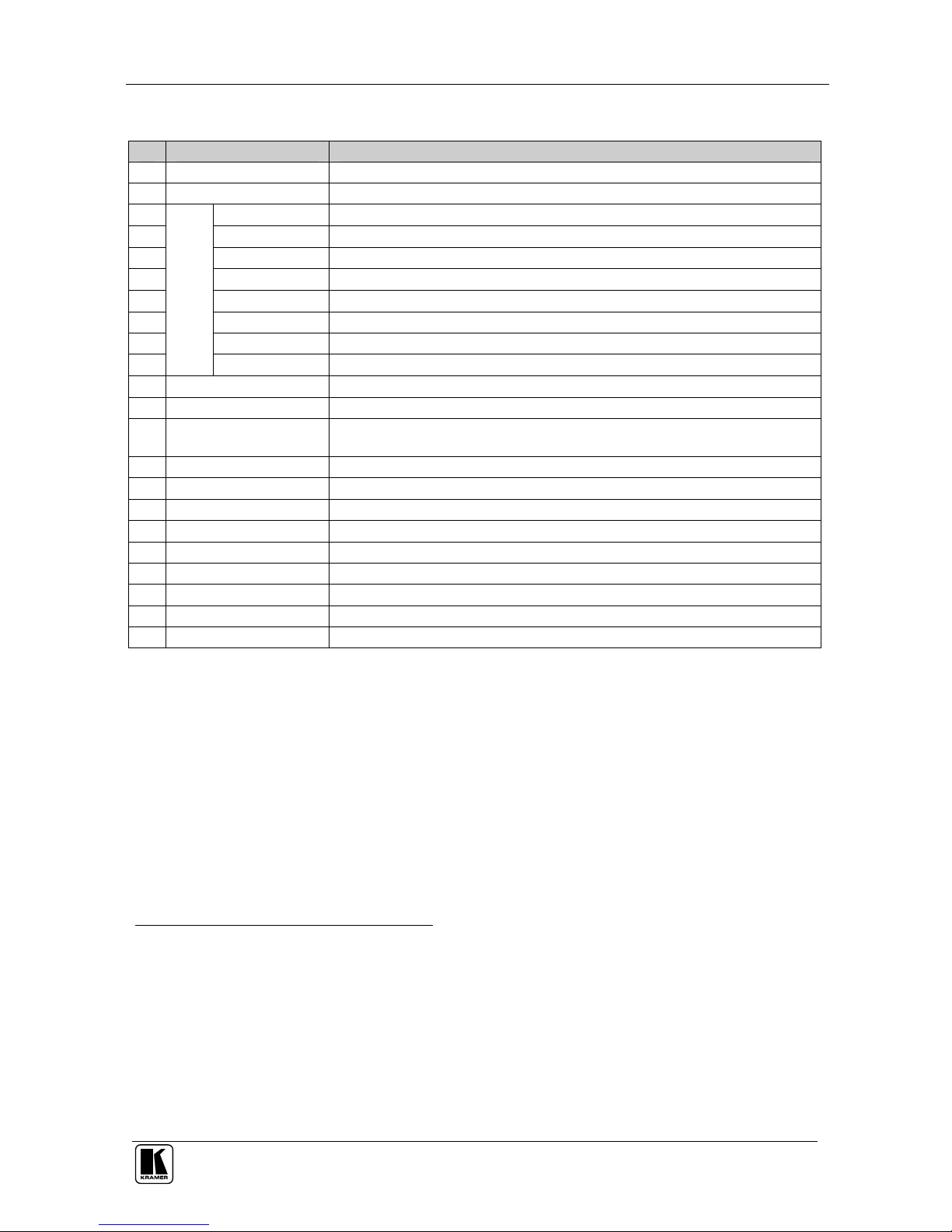
Table 1: Front Panel Presentation Switcher / Scaler Features
# Feature Function
1 POWER Switch Illuminated switch for turning the machine ON or OFF
2 IR Receiver / LED Red when the unit accepts IR remote commands
3 AV1 Press to select the composite video/audio source 1
4 AV2 Press to select the composite video/audio source 2
5 YC1 Press to select the s-Video (Y/C)/audio source 1
6 YC2 Press to select the s-Video (Y/C)/audio source 2
7 COMPONENT Press to select the component video/audio source
8 DVI Press to select the DVI/audio source
9 VGA2 1 Press to select the VGA/audio source 1
10
INPUT SELECTOR
Buttons
1
VGA2 2 Press to select the VGA/audio source 2
11 PIP Button3 Toggles the picture-in-picture function (see section 6.2)
12 BLANK Button Press to toggle between a blank screen (blue or black screen)4 and the display
13 MUTE Button Press to toggle between muting (blocking out the sound) and enabling the audio
output
14 FREEZE Button Press to freeze/unfreeze the output video image4
15 MENU Button Displays the OSD menu screen5
16 ENTER Button Moves to the next level in the OSD screen
17 - Button Decreases the range by one step in the OSD screen6
18 DOWN Button Moves down one step (in the same level) in the OSD screen6
19 UP Button Moves up one step (in the same level) in the OSD screen6
20 + Button Increases the range by one step in the OSD screen6
21 RESET TO VGA Button Press and hold to reset the output resolution to the default (640x480 @60Hz)
22 PANEL LOCK Button Press and hold to lock/unlock the front panel to prevent unintentional operation
1 When selected, button illuminates. See section 6.1 for details of how to program the INPUT SELECTOR buttons
2 Only the VP-724xl has 2 VGA INPUT SELECTOR buttons. The VP-719xl, VP-720xl and VP-723xl have just 1 VGA
button
3 Not available on the VP-719xl
4 Also available via each INPUT SELECTOR button, when programmed accordingly (see section 6.1)
5 Or moves to the previous level in the OSD screen
6 When pressing the button continuously, you can speed up its response. For step-by-step response, press and release the
button as many times as needed
KRAMER: SIMPLE CREATIVE TECHNOLOGY
Your Presentation Switcher / Scaler
10
P
R
E
L
I
M
I
N
A
R
Y
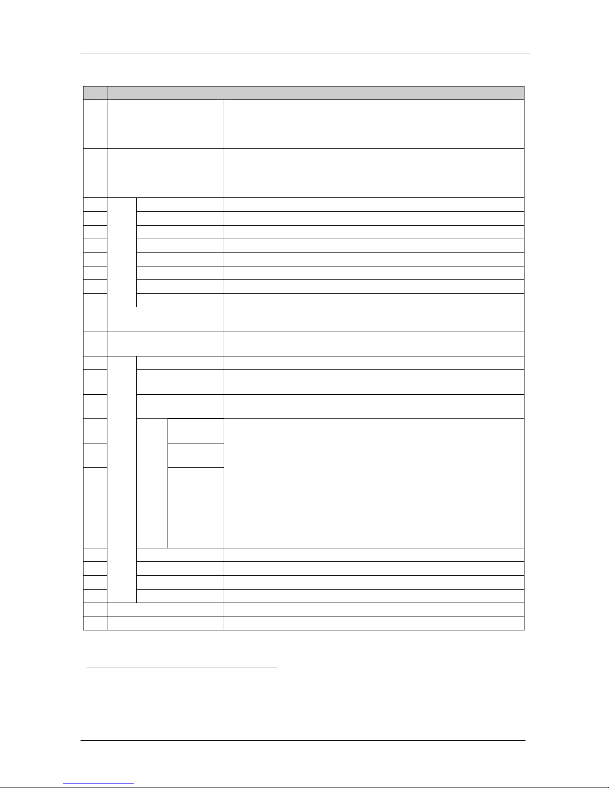
Table 2: Rear Panel Presentation Switcher / Scaler Features
# Feature Function
1 VIDEO OUT 1
HD15 Connector
Connects to the video acceptor (for example, a plasma display, projector or
monitor) that displays the scaled output
In the HDTV mode, the signal goes out via 3 PINS: PIN 1 is Pr, PIN 2 is Y,
PIN 3 is P
b
2 VIDEO OUT 2
HD15 Connector
Connects to the video acceptor (for example, a plasma display, projector or
monitor) that displays the scaled output
In the HDTV mode, the signal goes out via 3 PINS: PIN 1 is Pr, PIN 2 is Y,
PIN 3 Pb
3 AV1 Connects to the stereo audio input from composite video source 1
4 AV2 Connects to the stereo audio input from composite video source 2
5 YC1 Connects to the stereo audio input from s-Video source 1
6 YC2 Connects to the stereo audio input from s-Video source 2
7 COMP Connects to the stereo audio input from the component video source
8 DVI Connects to the stereo audio input from the DVI graphics source
9 VGA1 1 Connects to the stereo audio input from the VGA graphics source 1
10
AUDIO IN
Terminal Block
Connectors
VGA1 2 Connects to the stereo audio input from the VGA graphics source 2
11 LINE AUDIO OUT Terminal
Block Connector
Connects to the stereo audio acceptor
12 SPKR OUT
Terminal Block Connector
Connects to the speakers
13 DVI Connector Connects to the DVI (digital video interface) graphics source
14 VGA1 1 HD15
Connector
Connects to the VGA (analog interface) graphics source 1
15 VGA1 2 HD15
Connector
Connects to the VGA (analog interface) graphics source 2
16 Y RCA
Connector
17 Pb/Cb RCA
Connector
18
COMPONENT
Pr/Cr RCA
Connector
Connect to the component (Y, Pb/Cb, Pr/Cr) or RGB video source. If RGB
colorspace is used, connect as follows:
For video frequencies2, connect:
The Green to the Y connector
The Blue to the Pb/Cb connector
The Red to the Pr/Cr connector
For Graphics frequencies3, connect:
The Red to the Y connector
The Green to the Pb/Cb connector
The Blue to the Pr/Cr connector
19 YC2 4p Connector Connects to the s-Video source 2
20 AV2 RCA Connector Connects to the composite video source 2
21 YC1 4p Connector Connects to the s-Video source 1
22
VIDEO INPUTS
AV1 RCA Connector Connects to the composite video source 1
23 RS-232 DB 9 Connector Connects to PC or Serial Controller
24 Power Connector with Fuse AC connector enabling power supply to the unit
1 Only the VP-724xl has 2 VGA connectors. The VP-719xl, VP-720xl and VP-723xl have just 1 VGA connector
2 50Hz or 60Hz interlaced video
3 Including HD (480p, 576p, 720p and 1080i)

Connecting your Presentation Switcher / Scaler
11
P
R
E
L
I
M
I
N
A
R
Y
5 Connecting your Presentation Switcher / Scaler
To connect the VP-724xl for example1 (see Figure 9), do the following2:
1. Connect one or more of the following video sources:
2 composite video sources: “AV Source 1” and “AV Source 2”, to the
RCA connectors AV1 and AV2, respectively
2 s-Video sources: “s-Video Source 1” and “s-Video Source 2”, to the 4p
connectors, YC1 and YC2, respectively
A component video3 source, for example, a “Betacam VCR”, to the 3
RCA connectors, Y, Pb/Cb, and Pr/C
r
4
2 VGA graphics sources5: “VGA Graphics Source 1” and “VGA Graphics
Source 2”, to the HD15 connectors VGA 1 and VGA 2, respectively
A DVI graphics source, to the DVI connector
2. Connect the stereo audio sources6 (not illustrated in Figure 9):
The audio of “CV Source 1” and “CV Source 2” to the AUDIO IN AV1
and AV2 terminal block connectors, respectively
The audio of “s-Video 1” and “s-Video 2” to the AUDIO IN YC1 and
YC2 terminal block connectors, respectively
The audio of the component video source, the “Betacam VCR”, to the
AUDIO IN COMP terminal block connector
The audio of the “DVI Graphics Source ” to the AUDIO IN DVI terminal
block connector
The audio of “VGA Graphics Source 1” and “VGA Graphics Source 2” to
the AUDIO IN VGA1 and VGA 2 terminal block connectors, respectively
3. Connect the “VIDEO OUT 1” and “VIDEO OUT 2” HD15F connectors7
to the video acceptors, for example, a Plasma monitor and a VGA
monitor.
1 From this section on, all the information is relevant to the VP-719xl, VP-720xl, VP-723xl and VP-724xl machines, unless
noted otherwise
2 Switch OFF the power on each device before connecting it to your VP-724xl. After connecting your VP-724xl, switch on its
power and then switch on the power on each device
3 Sometimes called YUV, or Y, B-Y, R-Y, or Y, Pb, Pr
4 Alternatively, you can connect an RGB signal (not shown in Figure 9), as follows: Red to the Y connector, Green to the
Pb/Cb connector, and Blue to the Pr/Cr connector
5
Available only on the VP-724xl, other models in this series have only one VGA graphic source
6 As required. Not all devices need to be connected
7 In the HDTV mode, the signal goes out via 3 PINS: PIN 1 is Red or Pr, PIN 2 is Green or Y, PIN 3 is Blue or Pb
 Loading...