

Kramer VP-720DS, VP-723DS User Manual

Kramer Electronics, Ltd.
USER MANUAL
Models:
VP-720DS, Seamless Switcher / Scaler
VP-723DS, Seamless Switcher / Scaler

Contents
i
Contents
1 Introduction 1
2 Getting Started 1
3 Overview 1
4 Your Seamless Switcher / Scaler 3
5 Connecting the Seamless Switcher / Scaler 8
5.1 Connecting a PC 9
6 Understanding the Seamless Switcher / Scaler 11
6.1 Understanding the OUT Button Functionality 11
6.2 Understanding the PIP Button Feature 13
6.2.1 Activating the PIP Feature 13
6.2.2 PIP Characteristics 14
6.2.3 Toggling bet ween t he PIP and the Screen Source (SWAP) 14
6.2.4 Resizing the PIP 15
6.2.5 Moving the Position of the PIP 15
6.3 Locking and Unlocking the Front Panel 15
7 Operating the Seamless Switcher / Scaler 16
7.1 Switching and Scaling 16
7.1.1 Switching an Input 16
7.1.2 Choosing the Output Resolution 17
7.2 Controlling the Seamless Switcher / Scaler 17
7.3 Operating via the OSD MENU Screen 17
7.3.1 Controlling the Brightness and Contrast 18
7.3.2 Controlling the Gamma and Color 19
7.3.3 Selecting the Source 20
7.3.4 Controlling the Scale Geometry 20
7.3.5 Adjusting the Zoom Ratio and Position 22
7.3.5.1 Adjusting the Zoom Ratio 23
7.3.5.2 Adjusting the Zo om Position 23
7.3.6 Configuring via the Utility Screens 24
7.3.6.1 Choosing the G raphic Utility Settings 25
7.3.6.2 Choosing the V ideo U tility Settings 26
7.3.6.3 Choosing the Au d io U tility Se ttin g s 27
7.3.6.4 Choosing the PI P U tility Se ttings 27
7.3.6.5 Choosing the Se am le ss S w itch Utility Settings 29
7.3.6.6 Choosing the OS D U tility Se tting s 29
7.3.6.7 Choosing the Ou tpu t U tility Se ttin gs 30
7.3.6.8 Choosing Factory Reset 32
7.3.7 Verifying Configuration Details via the Information Screen 33

KRAMER: SIMPLE CREATIVE TECHNOLOGY
Contents
ii
7.3.8
Operating via the Infra-red Remote Control Transmitter 33
7.4 Upgrading Firm ware 36
8 Technical Specifications 36
9 Communication Protocol 37
Figures
Figure 1: Front Panels of the VP-720DS and VP-723DS, and their Rear Panel 4
Figure 2: Co nnecting the PC 9
Figure 3: Connecting the VP-720DS / VP-723DS Rear Panel 10
Figure 4: OUT LED Sequence 12
Figure 5: OSD PIP Status 14
Figure 6: OSD SWAP Status 14
Figure 7: Locking / Unlocking the Front Panel 15
Figure 8: OSD Input Status 16
Figure 9: OSD Output Status 17
Figure 10: MENU Screen 18
Figure 11: Menu Screen Icons 18
Figure 12: Brightness and Contrast Screen 18
Figure 13: Gamma and Color Screen 19
Figure 14: Gamma, Color Temperature/Manager User 1/2 Screen 19
Figure 15: Source Selection Screen 20
Figure 16: Geometry (Scale and Zoom) Screen 20
Figure 17: Geometry (Scale: Aspect Ratio and Nonlinear) Screen 21
Figure 18: Geometry (Scale: Aspect Ratio) Screen 21
Figure 19: Geometry (Zoom) Screen 22
Figure 20: OSD Enlarge Status 22
Figure 21: Zoom Ratio Adjustment Example 23
Figure 22: Zoom Position Adjustment Example 23
Figure 23: Geometry (Zoom Ratio) Screen 23
Figure 24: Preset Position Control Keys 24
Figure 25: Navigation Control Keys 24
Figure 26: Geometry (Zoom Position Adjustment) Screen 24
Figure 27: Utility Screen 25
Figure 28: Graphic Setting Utility Screen 25
Figure 29: Graphic Setting Color Format Utility Screen 26
Figure 30: Video Setting Utility Screen 26
Figure 31: Video Setting Standard Utility Screen 26
Figure 32: Audio Setting Utility Screen 27
Figure 33: Audio Setting Stereo Utility Screen 27
Figure 34: PIP Utility Screen 27
Figure 35: PIP Activation Utility Screen 28
Figure 36: PIP Source Utility Screen 28
Figure 37: PIP Size Utility Screen 28

Contents
iii
Figure 38: Seamless Switch Utility Screen 29
Figure 39: OSD Setting Utility Screen 29
Figure 40: OSD Size Utility Screen 30
Figure 41: OSD Source Prompt Activation Utility Screen 30
Figure 42: OSD Blank Color Utility Screen 30
Figure 43: Output Setting Utility Screen 31
Figure 44: Output Setting Resolution Utility Screen 31
Figure 45: Output Setting Refresh Rate Utility Screen 31
Figure 46: Output Setting User Mode Setting Utility Screen 32
Figure 47: Factory Reset Utility Screen 32
Figure 48: Information Screen 33
Figure 49: Infra-red Remote Control Transmitter 34
Tables
Table 1: Front Panel VP-720DS and VP-723DS, Seamless Switcher / Scaler Features 5
Table 2: Rear Panel VP-72 0DS and VP-723DS, Seamless Switcher / Scaler Features 7
Table 3: Selecting the Output Resolution 11
Table 4: User Mode Setting Definitions 32
Table 5: Infra-red Remote Control Transmitter Functions 35
Table 6: Technical Specifications of the VP-720DS/VP-723DS 36
Table 7: RS-232 Protocol 37
Table 8: RS-232 Communication Code 37
Table 9: RS-232 Read Command 39

P/N: 2900-0070144 A1
Addendum: Scalers Group
Additional Features of the Scaler Products Group according to
the Master-Firmware Ver-2.33 Release.
1. This version requires Slave Firmware version 1.06 or higher. The version can be
seen in the INFO section of the on-screen menu. Contact your Kramer service center if
you have any questions.
2. Improved functionality lets you select the PIP source via the RS-232
command. Sending an inappropriate PIP source command (request video PIP source
while the main video input is selected; or the same for graphic sources) will not cause
the unit to operate erroneously. In such a case, the unit will ignore the command and
return the message: “ineffective source”. This option does not apply to the VP-719DS.
3. Added PIP position(s) commands in the RS-232 protocol. These commands
let you input the absolute value (from 0 to 36) of the horizontal and vertical positions of
the PIP. For details, see the protocol table. This option does not apply to the VP-719DS.
4. Added new output resolution 1280x768. This resolution is marked with an
asterisk “*” to attract your attention to the fact that this is not a standard VESA
resolution and its parameters vary from manufacturer to manufacturer. Therefore, this
resolution must be used with caution. It is also possible to use the parameters of this
resolution in combination with the User Defined resolution (see below). There is also an
RS-232 command for this resolution. For details, see the protocol table.
5. Added 50 Hz output refresh rate. This is for special cases only. Many of the
modern screens and projectors have difficulties working with such a low frequency.
6. In the OSD under UTILITIES>ADVANCED there is new item: “Input
Button”. This item defines an action after repeatedly pressing the same input selection
button. This item has following options:
FREEZE/BLANK – this is the current situation (quoting from the user
manual: Press again (when the LED illuminates) to freeze the image; the LED
flashes. Press once again (when the LED flashes), to display a blank screen; the
LED flashes more slowly)). This remains the factory default
FREEZE – pressing the button toggles between LIVE and FREEZE
BLANK – pressing the button toggles between LIVE and BLANK
IGNORE – after selecting the source, the button is ignored
The settings also apply to the input buttons on the IR control.
7. Under the Utility>PIP Setting there is new item: “PIP Frame”. This feature
allows the enable/disable yellow frame around the PIP through the OSD or the new
RS-232 command: L 50AF. The RS-232 command allows PIP frame enable/disable
while the PIP is activated. However, before doing it via the OSD you must switch the
PIP OFF. While the frame is activated, pressing the UP and DOWN buttons on the front
panel and on the IR remote control would toggle through the PIP size settings. This
option does not apply to the VP-719DS.

Addendum: Scalers Group
A2
8. Under the Utility>Output Setting>User Mode Setting there is a new option:
“Set Current”. This feature lets you apply the parameters of the currently selected
output resolution to the User Define output resolution (Utility>Output
Setting>Resolution). This set of parameters can be used as a “starting point” to adjust
parameters according to the requirements of the signal receiver. The changes to the User
Define parameters are applied immediately and require confirmation in the same part of
the OSD.
9. In the OSD under UTILITIES>ADVANCED there is new item “User
Define Measure”. This feature lets you modify the automatically detected parameters
of the input graphic signal and save them in one of 3 sets for further use. The changes
are applied in real time and therefore can be monitored directly on the screen. This
feature is especially useful in working with non-standard input resolutions. The
following parameters can be changed:
H Total: Horizontal total
H Start: Horizontal active start point
H Active: Horizontal active region
V Start: Vertical active start point
V Active: Vertical active region
Ch Pump: Charge Pump current
Color: Color Format
10. Under the Utility>PIP Setting>PIP Size, there is a new option: “User
Define”. This feature lets you set the size of the PIP to your exact needs. To use this
option, select “User Define”, then press the “PIP User Define” bar and set the PIP
V-size (0-2551) and H-size (0-2551). This option does not apply to the VP-719DS.
11. By pressing the +, -, UP and DOWN buttons continuously, you can speed
up their response. For example, to roughly set the brightness to a higher level, open
“Brightness and Contrast”>Brightness, and press and hold the + button. For step-by-step
response, press and release these buttons as many times as needed.
12. New firmware supports an updated set of RS-232 protocol commands.
These commands are available on our Web site at http://www.kramerelectronics.com
13. Under Geometry>Scale>Aspect Ratio there is a new option: “User Define”.
This feature lets you adjust the geometry of the outputted picture.
14. A new refresh rate for HDTV resolutions. This new feature supports the
HDTV outputs with 50Hz refresh rate2.
1 255 corresponds to a full screen
2 This option applies to machines that support HDTV resolutions

Introduction
1
1 Introduction
Welcome to Kramer Electronics (since 1981): a world of unique, creative and
affordable solutions to the infinite range of problems that confront the video,
audio and presentation professional on a daily basis. In recent years, we have
redesigned and upgraded most of our line, making the best even better! Our
300-plus different models now appear in 8 Groups
1
, which are clearly defined
by function. Congratulatio ns on purchasing your Kramer VP-720DS
Seamless Switcher / Scaler and/or VP-723DS Seamless Switcher / Scaler,
which are ideal for the following typical applications:
• Presentation and conference room systems
• Producti on studios, rental and st aging
The VP-720DS and/or the VP-723DS package includes the following items:
• Seamless Switcher / Scaler
• Power cord
2
, Infra-red remote control transmitter and Null-modem
adapter
• This user manual
3
and the Kramer concise product catalog/CD
2 Getting Started
We recommend that you:
• Unpack the equipment carefully and save the original box and packaging
materials for possible future shipment
• Review the contents of this user manual
• Use Kramer high performance high resolution cables
4
3 Overview
The VP-720DS and VP-723DS are Seamless Switchers / Scalers designed for
a wide variety of presentation and multimedia applications. They are true
multi-standard video to RGB HV (pixel ) scalers t hat convert co mposite video,
1 GROUP 1: Distribution Amplifiers; GROUP 2: Video and Audio Switchers, Matrix Switchers and Controllers; GROUP 3 :
Video, Audio, VGA/XGA Processors; GROUP 4: Interfaces and Sync Processors; GROUP 5: Twisted Pair Interfaces;
GROUP 6: Accessories and Rack Adapters; GROUP 7: Scan Converters and Scalers; and GROUP 8: Cables and Connectors
2 We recommend that you use only the power cord that is supplied with this machine
3 Download up-to-date Kramer user manuals from the Internet at this URL: http://www.kramerelectronics.com/manuals.html
4 The complete list of Kramer cables is on our Web site at http://www.kramerelectronics.com (click “Cables and Connectors”
in the Products section)

KRAMER: SIMPLE CREATIVE TECHNOLOGY
Overview
2
s-Video, component video, VGA/SVGA/XGA/UXGA, and DVI signals to
the following user-selectable pixel rates:
• VGA (640x480)
• SVGA (800x600)
• XGA (1024x768)
• SXGA (1280x1024)
• UXGA (1600x1200)
• 852x1024
• 1024x1024
• 1366x768
• 1365x1024
1
• 1280x720
1
• 720x483
1
• 852x480
1
• 1400x1050
1
• A user definable output mode
2
The VP-723DS has 3 additional output modes used for high definition
television (HDTV): 480p, 720p, and 1080i. Both the VP-720DS and
VP-723DS are 7-input seamless presentation switchers, that:
• Digitally reprocess the signal to correct mastering errors, and regenerate
the video at a chosen line and pixel rate format, providing, for example,
native-resolution video for LCD, DLP and Plasma displays
• Facilitate scaling of any graphics resolution to any other resolution
3
• Incorporate a unique graphics-scaling engine with image enhancement
algorithms, which are built into the firmware
• Are specifically designed to improve video quality by reducing chroma noise
• Include a built-in Picture-in-Picture inserter
4
, letting you insert a video
source into a graphics background or vice versa, allowing the user to size and
position the shrunken inserted image anywhere on the screen
• Scale and zoom (to up to 400% of the original size)
In addition, both the VP-720DS and VP-723DS:
• Switch in true audio-follow-video mode
1 Not shown on the front panel
2 Recommended for advanced users only – non-standard settings may not be recognized by the display device
3 For example, scaling a VGA input to an UXGA output, or an SXGA input to an SVGA output
4 See section 6.2

Your Seamless Switcher / Scaler
3
• Include an OSD (on-screen display) for making the adjustments that can
be located anywhere on the screen, and can be doubled in size. The OSD can
be used to deactivate the source prompt, choose the color of the blank screen,
and choose from three seamless switching image transition speeds
• Include seven multi-functional input buttons that cycle between selecting
a source, freezing that source, or deactivating that source (and displaying a
blank screen)
• Include a front panel lock
• Incorporate full ProcAmp
1
processing for video and audio correction
• Offer high quality de-interlacing 3:2/2:2 pull down
2
• Can provide non-linear scaling for 4:3, 16:9 transformation
3
• Support firmware upgrade via RS-232
• Include non-volatile memory that retains the last setting, after switching
the power off and then on again
Control the VP-720DS and/or VP-723DS:
• From the front panel OSD control buttons
• Remotely, from the infra-red remote control transmitter
• Remotely, via RS-232
Achieving the best performance means:
• Connecting only good quality connection cables, thus avoiding
interference, deterioration in signal quality due to poor matching, and elevated
noise levels (often associated with low quality cables)
• Avoiding interference from neighboring electrical appliances that may
adversely influence signal quality and positioning your Kramer VP-720DS
and/or VP-723DS away from moisture, excessive sunlight and dust
4 Your Seamless Switcher / Scaler
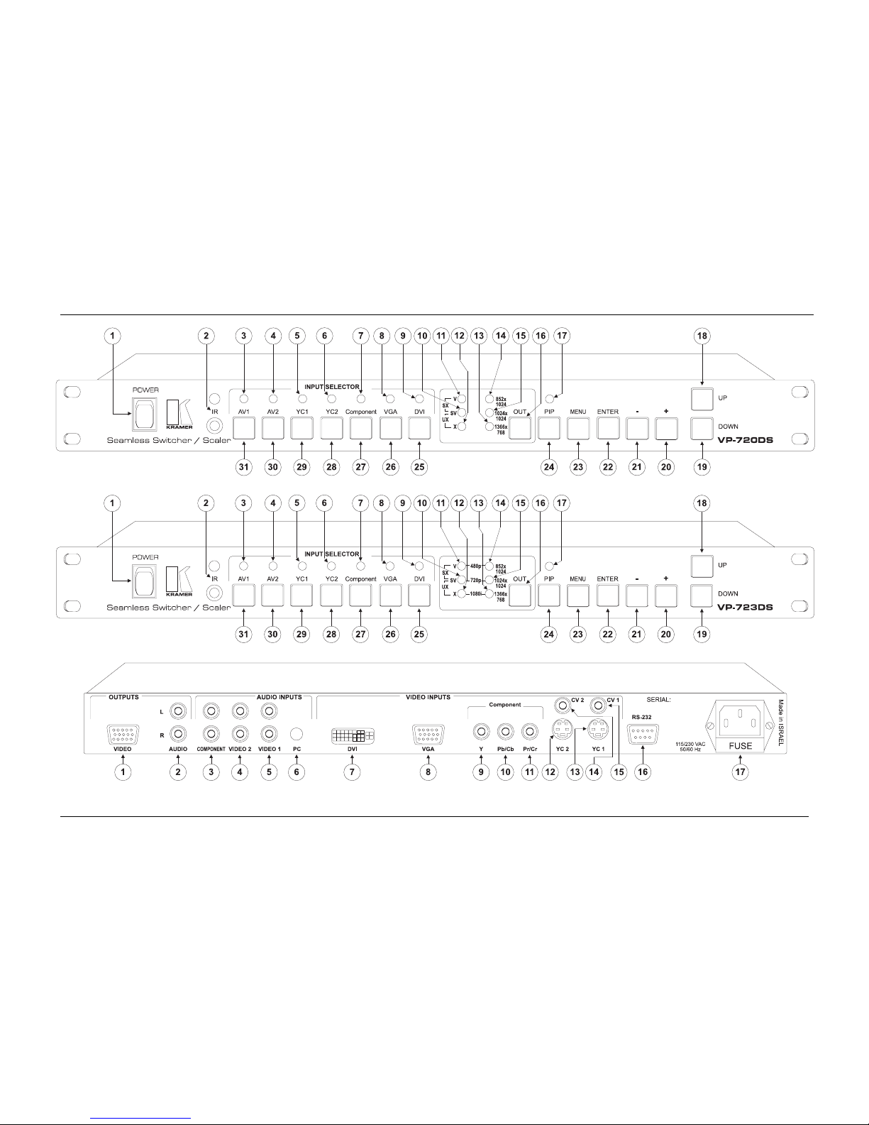
Figure 1 illustrates the front panels of the VP-720DS and VP-723DS, as well
as the rear panel. The latter is identical on both the VP-720DS and
VP-723DS. Table 1 and Table 2 define the front and rear panels of the
VP-720DS and VP-723DS, respectively.
1 Processing amplification enables adjustment of different video and audio signal parameters
2 Accommodates the frame-rate of a converted movie (24 frames per second) to video frequencies (25 fra mes per second
(PAL); 30 frames per second (NTSC)
3 See Figure 18
KRAMER: SIMPLE CREATIVE TECHNOLOGY
Your Seamless Switcher / Scaler
4
Figure 1: Front Panels of the VP-720DS and VP-723DS, and their Rear Panel
Your Seamless Switcher / Scaler
5
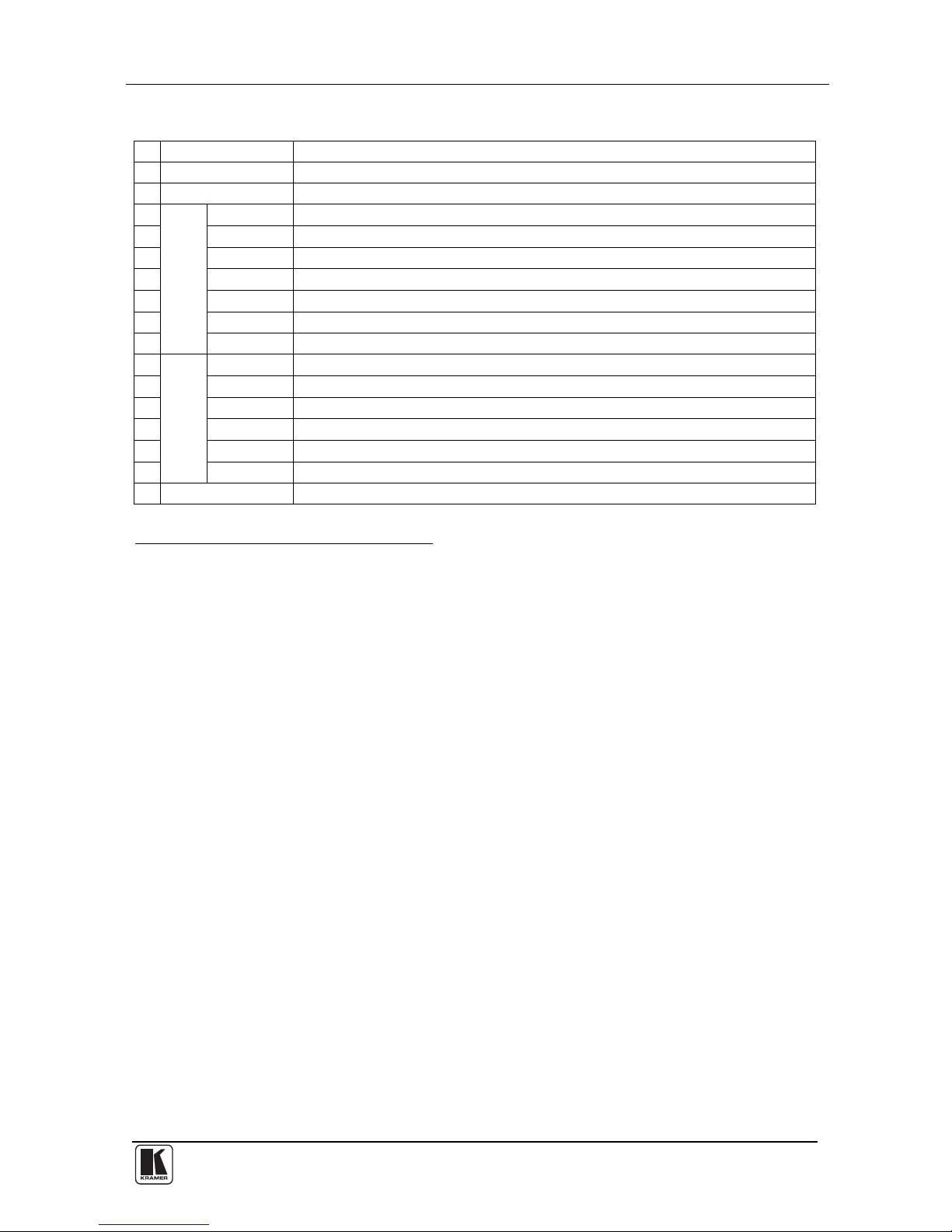
Table 1: Front Panel VP-720DS and VP-723DS, Seamless Switcher / Scaler Features
# Feature Function
1 POWER Switch Illuminated switch supplying power to the unit
2 IR Receiver / LED Gre en when the unit will accept IR remote commands
3 AV1 Illuminates1 when the composite video / audio source 1 is selected
4 AV2 Illuminates1 when the composite video / audio source 2 is selected
5 YC1 Illuminates1 when the s-Video (Y/C) / audio source 1 is selected
6 YC2 Illuminates1 when the s-Video (Y/C) / audio source 2 is selected
7 Component Illuminates1 when the component video / audio source is selected
8 VGA Illuminates1 when the VGA / audio source is selected
9
INPUT SELECTOR
LEDs
DVI Illuminates1 when the DVI / audio source is selected
10
SV Illuminates when the SVGA resolution is selected2
11
V Illuminates when the VGA resolution is selected3
12
X Illuminates when the XGA res ol u tion is select ed4
13
1366x768 Illuminates when the 13 66x768 resolution is select ed5
14
852x1024 Illuminates when the 852x1024 resolution is selected6
15
OUT LEDs
1024x1024 Illuminates when the 1024x1024 resolution is selected7
16 OUT Button Selects the output resolution and illuminates the appropriate LED8
1 Flashes when the image is frozen, and flashes more slowly when a blank screen is displayed
2 Illuminates with the V LED when the SXGA resolution is selected, with the X LED when the UXGA resolution is selected,
with the 852x1024, 1024x1024 and 1366x768 LEDs when the 8 52x480 resolution is selected, with the 1024x1024 LED when
720p is selected (VP-723DS only), and with all the other LEDs when UserDefine is selected
3 Illuminates with the SV LED when the SXGA resolution is selected, with the 852x1024, 1024x1024 and 1366x768 LEDs
when the 720x483 resolution is selected, with the 852x1024 LED when 480p is selected (VP-723DS only), and with all the
other LEDs when UserDefine is selected
4 Illuminates with the SV LED when the UX GA resolution is selected, with the 852x1024, 1024x1024 and 1366x768 LEDs
when the 1400x1050 resolution is selected, with the 1366x768 LED when 1080i is selected (VP-723DS only), and with all the
other LEDs when UserDefine is selected
5 Illuminates with the 1024x1024 LED when the 1280x720 (not shown on the front panel) resolution is selected, with the V,
852x1024, and 1024x1024 LEDs when the 7 20x483 resolution is selected, with the SV, 852x1024, and 1024x1 024 LEDs
when the 852x480 resolution is selected, with the X, 852x1024, and 1024x1024 LEDs when the 1400x1050 resolution is
selected, with the X LED when 1080i is selected (VP-723DS only), and with all the other LEDs when UserDefine is selected
6 Illuminates with the 1024x1024 LED when the 1365x1024 (not shown on the front panel) resolution is selected, with the V,
1024x1024, and 1366x768 LEDs when the 7 20x483 resolution is selected, with the SV, 1024x1024, and 1366x 768 LEDs
when the 852x480 resolution is selected, with the X, 1024x1024, and 1366x768 LEDs when the 1400x1050 resolution is
selected, with the V LED when 480p is selected (VP-723DS only), and with all the other LEDs when UserDefine is selected
7 Illuminates with the 852x1024 LED when 1365x1024 (not shown on the front panel) resolution is selected, with the
1366x768 LED when the 1280x720 (not shown on the front panel) is selected, with the V, 852x1024, and 1366x768 LEDs
when the 720x483 resolution is selected, with the SV, 852x1024, and 1366x768 LEDs when the 852x480 resolution is
selected, with the X, 852x1024, and 1366x768 LEDs when the 1400x1050 resolution is selected, with the SV LED when the
720p is selected (VP-723DS only), and with all the other LEDs when UserDefine is selected
8 See section 6.1
KRAMER: SIMPLE CREATIVE TECHNOLOGY
Your Seamless Switcher / Scaler
6
# Feature Function
17 PIP LED Illuminates when the picture-in-picture function is selected
18 UP Button Moves up one step (in the same level) in the OSD screen
19 DOWN Button Moves down one step (in the same level) in the OSD screen
20 + Button Increases the range by one step in the OSD screen
21 - Button Decreases the range by one step in the OSD screen
22 ENTER Button Moves to the next level in the OSD screen
23 MENU Button Displays the OSD Menu screen1 and locks/unlocks the front panel2
24 PIP Button Selects the picture-in-picture function and illuminates the PIP LED3
25
DVI Press4 to select the DVI / audio source and illuminate the DVI LED
26
VGA Press4 to select the VGA / audio source and illuminates the VGA LED
27
Component Press4 to select the component video/audio source and illuminate the
component LED
28
YC2 Press4 to select the s-Video (Y/C) / audio source 2 and illuminate the YC2 LED
29
YC1 Press4 to select the s-Video (Y/C) / audio source 1 and illuminate the YC1 LED
30
AV2 Press4 to select the composite video / audio source 2 and illuminate the AV2
LED
31
INPUT SELECTOR Buttons
AV1 Press4 to select the composite video / audio source 1 and illuminate the AV1
LED
1 Or moves to the previous level in the OSD screen
2 See section 6.3
3 See section 6.2
4 Press again (when the LED illuminates) to freeze the image; the LED flashes. Press once again (when the LED flashes), to
display a blank screen; the LED flashes more slowly. Alternatively, to freeze the image, press the FREEZE key on the
infra-red remote control transmitter (see Figure 49)

Your Seamless Switcher / Scaler
7
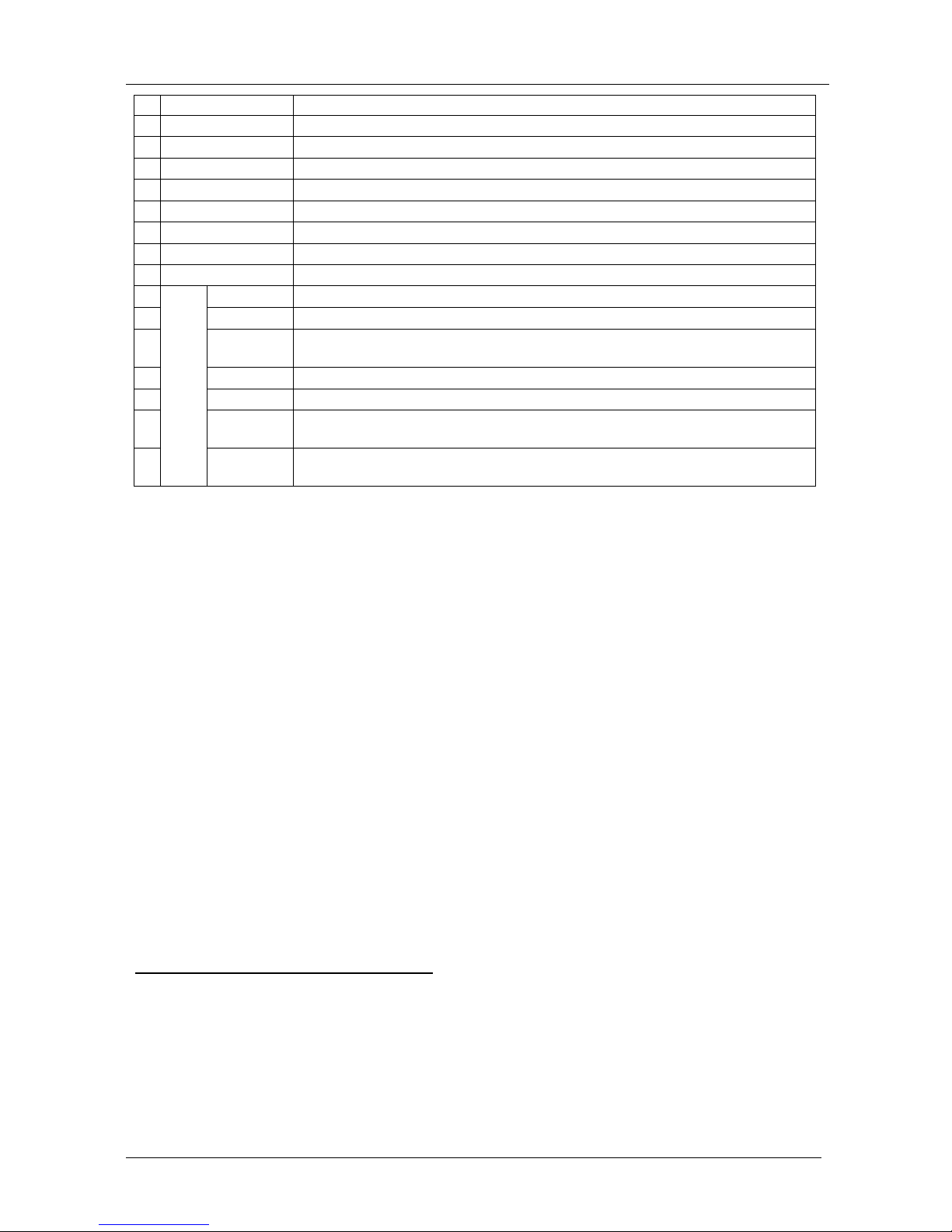
Table 2: Rear Panel VP-720DS and VP-723DS, Seamless Switcher / Scaler Features
# Feature Function
1 VIDEO HD15
Connector
Connects to the video acceptor (for example, Plasma display,
projector or monitor) that displays the scaled output (with the OSD
superimposed over it)
In the HDTV mode (VP-723DS), the signal goes out via 3 PINS:
PIN 1 is Red or P
r
, PIN 2 is Green or Y, PIN 3 is Blue or Pb
2
OUTPUTS
AUDIO L and R RCA
Connectors
Connects to the left and right stereo audio acceptors
3 COMPONENT L and R
RCA Connectors
Connects to the left and right stereo audio inputs from the
COMPONENT video source
4 VIDEO 2 L and R RCA
Connectors
Connects to the left and right stereo audio inputs from one of the
composite or s-Video sources
1
5 VIDEO 1 L and R RCA
Connectors
Connects to the left and right stereo audio inputs from one of the
composite or s-Video sources
2
6
AUDIO INPUTS
PC 3.5 mm Socket Connects to the audio input from either the DVI (digital video
interface) grap hics sou rce or th e VGA analog graphics source
7 DVI Connector Connects to the DVI (digital video interface) graphics source
8 VGA HD15 Connector Connects to the VGA (analog interface) graphics source
9 Y
10
Pb/Cb
11
Component
RCA
Connectors
Pr/Cr
Connect to the component video source
3
12
YC 2 4p Connector Connects to the s-Video source 2
13
YC 1 4p Connector Connects to the s-Video source 1
14
CV 2 RCA Connector Connects to the composite video source 2
15
VIDEO INPUTS
CV 1 RCA Connector Connects to the composite video source 1
16 RS-232 DB 9 Connector Connects to PC or Serial Controller
17 Power Connector with FUSE AC connector enabling power supply to the unit
1 Either CV 2 or YC 2
2 Either CV 1 or YC 1
3 Or to an RGB signal; connect RED to the “Y” connector , GREEN to the “Pb/Cb ” connector, and BLUE to the “Pr/Cr ” connector

KRAMER: SIMPLE CREATIVE TECHNOLOGY
Connecting the Seamless Switcher / Scaler
8
5 Connecting the Seamless Switcher / Scaler
Using the VP-720DS or VP-723DS you can select any one of the 7 inputs
and scale that input to the output at the set
1
resolution.
To connect the VP-720DS or VP-723DS, connect the following
2
to the rear
panel, as the example in Figure 3 illustrates:
1. Connect one or more of the following video sources:
• 2 composite video sources, “Composite Video Source 1” and “Composite
Video Source 2”, to the RCA connectors CV 1 and CV2, respectively
3
• 2 s-Video sources: “s-Video Source 1” and “s-Video Source 2”, to the 4p
connectors, YC 1 and YC 2, respectively
• A component video
4
source, for example, a Betacam VCR (as illustrated
in Figure 3), to the 3 RCA connectors, Y, Pb/Cb, and Pr/C
r
5
• A VGA graphics source, for example, a PC with an analog graphics
output, to the VGA HD15F connector
• A DVI graphics source, for example, a PC with a digital graphics output,
to the DVI connector
2. Connect the stereo audio sources, as illustrated in Figure 3. In particular:
• The audio of the “Composite Video Source 1” to the AUDIO INPUT
VIDEO 1 pair of RCA connectors
6
• The audio of the “s-Video Source 2” to the AUDIO INPUT VIDEO 2 pair
of RCA connectors
7
• The audio of the Component video source, the Betacam VCR, to the
AUDIO INPUT COMPONENT pair of RCA connectors
• The audio of the DVI Graphics Source to the AUDIO INPUT PC 3.5mm
socket
8
. Alternatively, connect the audio from the VGA Graphics Source (not
illustrated in Figure 3)
1 For details of how to set the output resolution on the VP-720DS and VP-723DS, refer to section 6.1
2 Switch OFF the power on each device before connecting it to your Seamless Switcher / Scaler. After connecting your
Seamless Switcher / Scaler, switch on its power and then switch on the power on each device
3 Connection to CV 2 is not shown in the example in Figure 3
4 Sometimes called YUV, or Y, B-Y, R-Y, or Y, Pb, Pr
5 Alternatively, you can connect an RGB signal (not shown in Figure 3), as follows: RED to the “Y” connector, GREEN to
the “Pb/Cb” connector, and BLUE to the “Pr/Cr” connector
6 The VIDEO 1 connectors are common to CV 1 and YC 1
7 The VIDEO 2 connectors are common to CV 2 and YC 2
8 The PC connector is common to DVI and VGA

Connecting the Seamless Switcher / Scaler
9
3. Connect the VIDEO OUTPUT HD15F connector1 to the video acceptor,
for example, a projector or a Plasma monitor (as shown in Figure 3), and
connect the AUDIO OUTPUT pair of RCA connectors to the audio
acceptor, for example, a power amplifier.
4. The power cord
2
(the power connector is not illustrated in Figure 3).
5. A PC (optional), as section 5.1 describes.
5.1 Connecting a PC
You can connect a PC (or other controller) to the VP-720DS or VP-723DS
via the RS-232 port for remote control, and for upgrading the firmware, as
section 7.4 describes.
To connect a PC to the VP-720DS or VP-723DS unit, using the Nul l -mod e m
adapter provided with the machine (recommended):
• Connect the RS-232 DB9 rear panel port on the VP-720DS or VP-723DS
unit to the Null-modem adapter and connect the Null-modem adapter with a 9
wire flat cable to the RS-232 DB9 port on your PC
To connect a PC to a VP-720DS or VP-723DS unit, without using a
Null-modem adapter:
• Connect the RS-232 DB9 port on your PC to the RS-232 DB9 rear panel
port on the VP-720DS or VP-723DS unit, forming a cross-connectio n
3
, as
Figure 2 illustrates
DB9 (To Seamless
Switcher
/
Scaler
)
DB9 (From PC
)
Figure 2: Connecting the PC
1 In the HDTV mode, the signal goes out via 3 PINS: PIN 1 is Red or Pr, PIN 2 is Green or Y, PIN 3 is Blue or Pb
2 We recommend that you use only the power cord that is supplied with this machine
3 Also known as a Null-modem connection
 Loading...