

Page 1
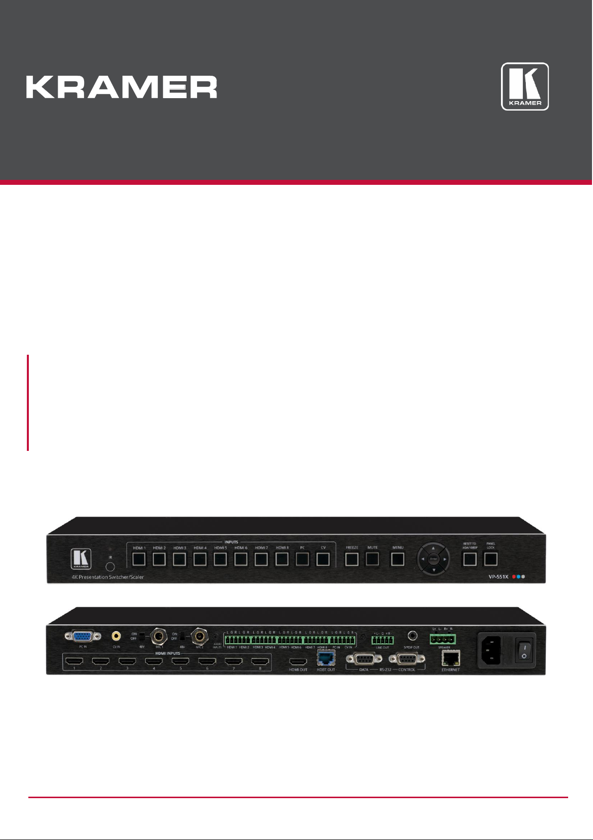
P/N: 2900-301296 Rev 7 www.kramerAV.com
USER MANUAL
MODEL:
VP-551X
4K Presentation Matrix Switcher Scaler
Page 2

Kramer Electronics Ltd.
VP-551X – Contents
i
Contents
Introduction 1
Getting Started 1
Overview 2
Typical Applications 3
Defining VP-551X 4K Presentation Matrix Switcher Scaler 4
Mounting VP-551X 6
Connecting VP-551X 7
Connecting Output to Balanced/Unbalanced Stereo Audio Acceptor 8
Connecting Balanced/Unbalanced Stereo Audio Source to Balanced Input 8
Microphone Setup 9
Wiring the RJ-45 Connectors 9
Operating and Controlling VP-551X 10
Using Front Panel Buttons 10
Controlling Device Via OSD Menu 11
Operating via Ethernet 19
Using the Embedded Webpages 22
Browsing VP-551X Webpages 22
Selecting Input 24
Setting Device Parameters 27
Changing Output Settings 30
Managing HDCP 33
Managing EDID 34
Setting Audio Parameters 35
Setting RS-232 Port Function 37
Setting Webpage Access 41
Defining Auto Sync Off 44
Defining Auto Switching Mode 45
Defining Lock Mode 45
System Maintenance 46
Viewing Device Information 47
Upgrading the Firmware 48
Technical Specifications 49
Default Communication Parameters 51
Input Resolutions Support 51
Output Resolution Support 52
Default EDID 52
Protocol 3000 55
Understanding Protocol 3000 55
Protocol 3000 Commands 56
Result and Error Codes 64
Page 3

Kramer Electronics Ltd.
VP-551X – Introduction
1
Introduction
Welcome to Kramer Electronics! Since 1981, Kramer Electronics has been providing a world
of unique, creative, and affordable solutions to the vast range of problems that confront the
video, audio, presentation, and broadcasting professional on a daily basis. In recent years,
we have redesigned and upgraded most of our line, making the best even better!
Getting Started
We recommend that you:
• Unpack the equipment carefully and save the original box and packaging materials for
possible future shipment.
• Review the contents of this user manual.
Go to www.kramerav.com/downloads/VP-551X to check for up-to-date user manuals,
application programs, and to check if firmware upgrades are available (where appropriate).
Achieving the Best Performance
• Use only good quality connection cables (we recommend Kramer high-performance,
high-resolution cables) to avoid interference, deterioration in signal quality due to poor
matching, and elevated noise levels (often associated with low quality cables).
• Do not secure the cables in tight bundles or roll the slack into tight coils.
• Avoid interference from neighboring electrical appliances that may adversely influence
signal quality.
• Position your Kramer VP-551X away from moisture, excessive sunlight and dust.
Safety Instructions
Caution:
• This equipment is to be used only inside a building. It may only be connected to other
equipment that is installed inside a building.
• For products with relay terminals and GPI\O ports, please refer to the permitted rating
for an external connection, located next to the terminal or in the User Manual.
• There are no operator serviceable parts inside the unit.
Warning:
• Use only the power cord that is supplied with the unit.
• Disconnect the power and unplug the unit from the wall before installing.
• Do not open the unit. High voltages can cause electrical shock! Servicing by qualified
personnel only.
• To ensure continuous risk protection, replace fuses only according to the rating
specified on the product label which located on the bottom of the unit.
Page 4

Kramer Electronics Ltd.
VP-551X – Introduction
2
Recycling Kramer Products
The Waste Electrical and Electronic Equipment (WEEE) Directive 2002/96/EC aims to reduce
the amount of WEEE sent for disposal to landfill or incineration by requiring it to be collected
and recycled. To comply with the WEEE Directive, Kramer Electronics has made
arrangements with the European Advanced Recycling Network (EARN) and will cover any
costs of treatment, recycling and recovery of waste Kramer Electronics branded equipment
on arrival at the EARN facility. For details of Kramer’s recycling arrangements in your
particular country go to our recycling pages at www.kramerav.com/support/recycling.
Overview
Congratulations on purchasing your Kramer VP-551X 4K Presentation Matrix Switcher
Scaler.
VP-551X is a versatile, professional presentation scaler/switcher for 4K@60 (4:4:4) HDMI™,
and for VGA and composite video signals. The unit scales the video and provides options to
use the embedded HDMI audio or to select the companion audio channel from one of ten
analog audio input signals. After processing and scaling, the embedded AV signal is sent to
the HDMI and the HDBaseT outputs simultaneously, and the audio is also sent to a balanced
stereo audio output, S/PDIF digital output and a pair of loudspeakers.
VP-551X provides exceptional quality, advanced and user-friendly operation, and flexible
control.
Exceptional Quality
• High-Resolution Video – Supports and scales to/from resolutions up to 4K@60Hz
(4:4:4) on the HDMI inputs and output, and 4K@60Hz (4:2:0) on the HDBaseT output.
• Complies with HDMI, HDCP 2.2 and HDR10 standards.
• HDMI Support – HDR10, CEC, xvYCC color (on input), Dolby TrueHD/DTS-HD Master
Audio (by-pass), as specified in HDMI 2.0 as specified in HDMI 2.0.
• Professional Video Quality – Provides selectable aspect ratios (full, best fit, over scan,
under scan, letter box and pan scan). Includes built-in ProcAmp for color, hue,
sharpness, noise, contrast and brightness control. Supports PixPerfect™ Scaling
Technology, Kramer’s precision pixel mapping and high-quality scaling technology.
High-quality 3:2 and 2:2 pull-down de-interlacing and full up-scaling and down-scaling of
all video input signals.
• High-Performance Switcher/Scaler – Scales HDMI, VGA and Composite video signals
for output to two mirrored outputs: HDMI and HDBaseT. Constant output sync prevents
signal disruption when switching between inputs and when no video is detected.
• Powerful Audio Features – Including DSP with audio equalization, mixing, delay and
more.
• HDTV Compatible.
Page 5

Kramer Electronics Ltd.
VP-551X – Introduction
3
Advanced and User-friendly Operation
• 4K and Legacy Inputs – 8 4K@60 (4:4:4) HDMI inputs, 1 VGA input, and 1 CV
(composite video) input.
• Versatile Powering Options – Powered by universal power supply (100-240V AC) and
provides PoE power to a compatible HDBaseT device.
• Non-Volatile Memory – Saves final settings before shutdown and retains them for next
power up.
• Convenient Control Options – Local control via front panel buttons, RS-232, IR remote,
and OSD. Long-distance control via embedded webpages and Ethernet.
• Easy Installation – 19” enclosure for rack mounting a unit in a 1U rack space with
included rack ears and universal 100-240V AC power connection.
• Auto-switching and auto-scanning of inputs.
• Advanced EDID management per input.
Flexible Connectivity
• Versatile Audio Options – Includes a companion analog audio input for each of the 10
video inputs, enabling the user to embed a separate analog audio channel into each
video signal or to bypass an embedded audio input (for example, to support
multi-channel, compressed audio formats like Dolby and DTS).
• Provides 2 independent microphone inputs on 6.3mm connectors (each with optional
48V phantom power) for mixing, switching or talk–over.
• On the output, besides the audio embedded on HDMI and HDBaseT outputs, the audio
signal is also extracted (de-embedded) and output as balanced stereo analog audio,
and as digital audio through an S/PDIF connected device, as well as amplified to 20W
per channel for connection to loudspeakers.
• Video Inputs – 8 HDMI, 1 PC and 1 CV.
• Video Outputs – 1 HDBaseT and 1 HDMI.
Typical Applications
VP-551X is ideal for the following typical applications:
• Projection systems in conference rooms, boardrooms, hotels and churches.
• Home theater up-scaling.
Controlling your VP-551X
Control your VP-551X directly via the front panel push buttons (with on-screen menus, or:
• By RS-232 serial commands transmitted by a touch screen system, PC, or other serial
controller.
• Remotely, from the infrared remote control transmitter.
• Via the Ethernet using built-in user-friendly webpages.
Page 6
Kramer Electronics Ltd.
VP-551X – Defining VP-551X 4K Presentation Matrix Switcher Scaler
4
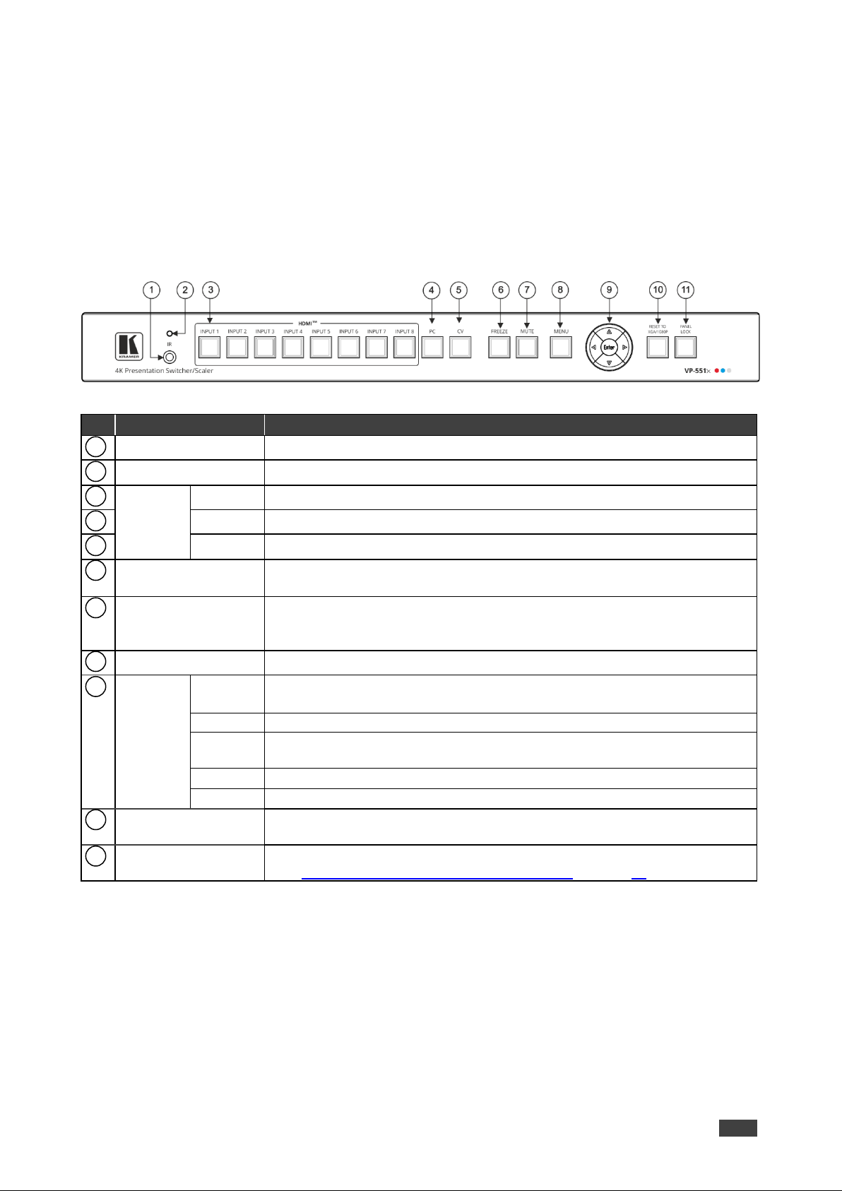
Defining VP-551X 4K Presentation Matrix Switcher Scaler
This section defines VP-551X.
Figure 1: VP-551X 4K Presentation Matrix Switcher Scaler Front Panel
#
Feature
Function
IR Receiver
Receives signals from the remote-control transmitter.
IR LED
Lights when the unit accepts IR remote commands.
HDMI™
Press to select the HDMI input (from INPUT 1 to INPUT 8).
PC
Press to select the computer graphics input.
CV
Press to select the composite video input.
FREEZE Button
Press to freeze/unfreeze the output video image.
Not applicable when in video bypass mode.
MUTE Button
Press to toggle between muting (blocking out the sound) and enabling the
audio output (both line and speakers).
Muting the audio is not applicable when in audio bypass mode.
MENU Button
Press to enter/escape the on-screen display (OSD) menu.
Navigation
Buttons
Press to decrease numerical values or select from several definitions.
When not within the OSD menu mode, press to decrease the output volume.
Press to move up the menu list.
Press to increase numerical values or select from several definitions.
When not within the OSD menu mode, press to increase the output volume.
Press to move down the menu list.
ENTER
Press to accept changes and change the SETUP parameters.
RESET TO
XGA/1080p Button
Press and hold for about 5 seconds to toggle resetting the video resolution to
XGA or 1080p.
PANEL LOCK Button
Press and hold for about 3 seconds to lock/unlock the front panel buttons
(see Locking and Unlocking Front Panel Buttons on page 10).
1
2
3 4 5
6 7 8
9
Page 7
Kramer Electronics Ltd.
VP-551X – Defining VP-551X 4K Presentation Matrix Switcher Scaler
5
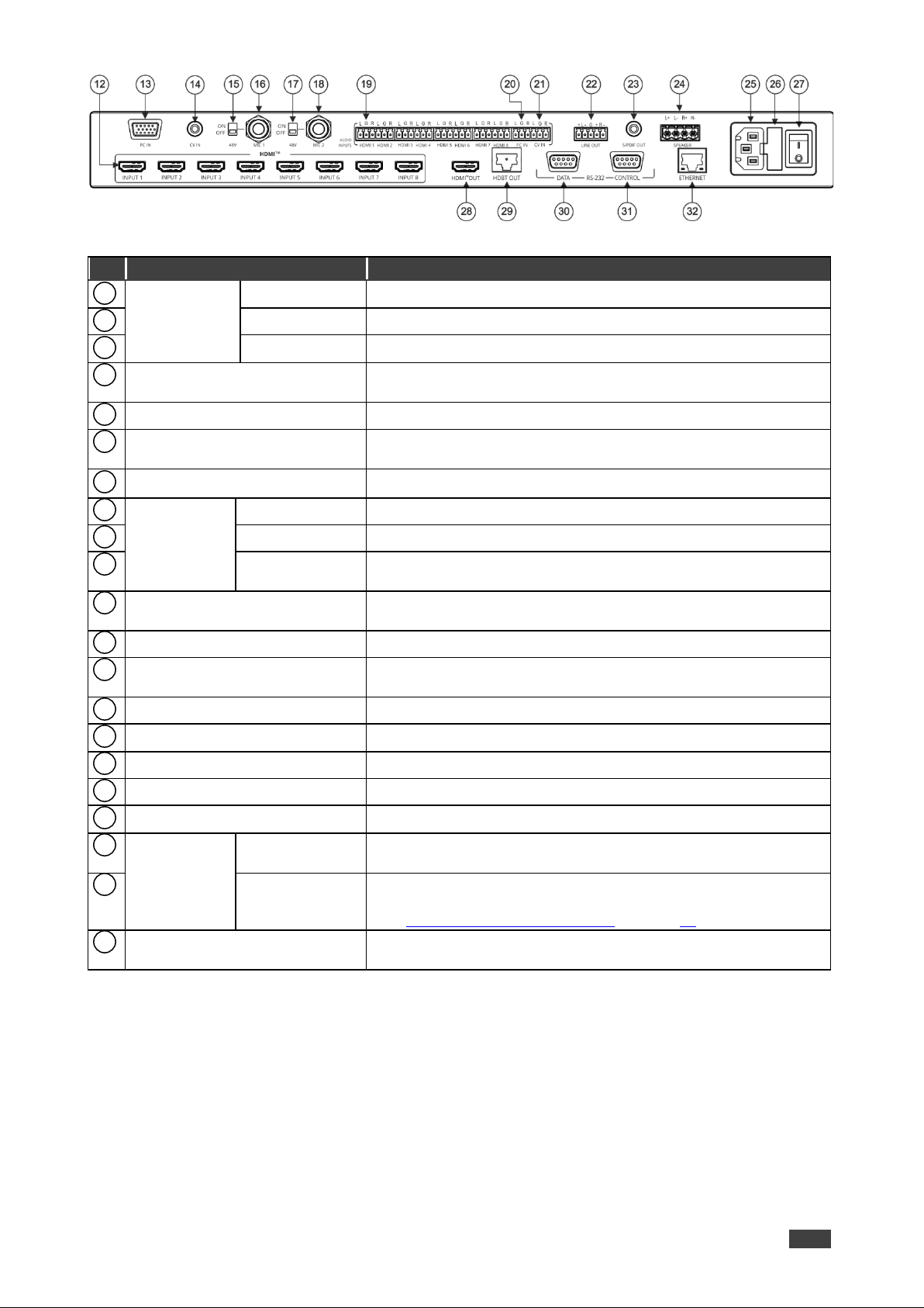
Figure 2: VP-551X 4K Presentation Matrix Switcher Scaler Rear Panel
#
Feature
Function
VIDEO INPUT
Connectors
HDMI™
Connect to an HDMI source (from INPUT 1 to INPUT 8).
PC 15-pin HD
Connect to a computer graphics source.
CV RCA
Connect to a composite video source.
48V MIC 1 Switch
Move up (ON) to select phantom power for a condenser type
microphone; down (OFF) to select a dynamic type microphone.
MIC 1 6mm Jack
Connect to the microphone source 1.
48V MIC 2 Switch
Move up (ON) to select phantom power for a condenser type
microphone; down (OFF) to select a dynamic type microphone.
MIC 2 6mm Jack
Connect to the microphone source 2.
AUDIO INPUT
Unbalanced
Stereo
Terminal
Blocks
HDMI
Connect to an analog audio HDMI source (from 1 to 8).
PC IN
Connect to an analog audio computer graphics source.
CV IN
Connect to an analog audio composite video source.
LINE OUT Balanced Stereo 5-pin
Terminal Block Connector
Connect to a balanced stereo analog audio acceptor.
S/PDIF OUT RCA Connector
Connect to a digital audio acceptor.
SPEAKER 4-pin Terminal Block
Connector
Connect to a pair of loudspeakers.
Mains Socket
Connect the mains power cord.
Mains Fuse Holder
Fuse for protecting the device.
Power Switch
Switch for turning the unit ON or OFF.
HDMI™ OUT
Connect to the HDMI acceptor.
HDBT OUT RJ-45 Connector
Connect to an HDBaseT receiver.
RS-232 9-pin
D-sub
Connector
DATA
Connect to a PC or controller to tunnel RS-232 via HDBT OUT or
connect to the output display to control it.
CTRL
Connect to a PC or remote controller to control VP-551X or
connect to a device which you want to control via the VP-551X
(see Controlling an External Device on page 38).
ETHERNET RJ-45 Connector
Connects to the PC or other Serial Controller through computer
networking.
Page 8
Kramer Electronics Ltd.
VP-551X – Mounting VP-551X
6
Mounting VP-551X
This section provides instructions for mounting VP-551X. Before installing, verify that the
environment is within the recommended range:
• Operation temperature – 0 to 40C (32 to 104F).
• Storage temperature – -40 to +70C (-40 to +158F).
• Humidity – 10% to 90%, RHL non-condensing.
Caution:
• Mount VP-551X before connecting any cables or power.
Warning:
• Ensure that the environment (e.g., maximum ambient temperature & air flow) is
compatible for the device.
• Avoid uneven mechanical loading.
• Appropriate consideration of equipment nameplate ratings should be used for avoiding
overloading of the circuits.
• Reliable earthing of rack-mounted equipment should be maintained.
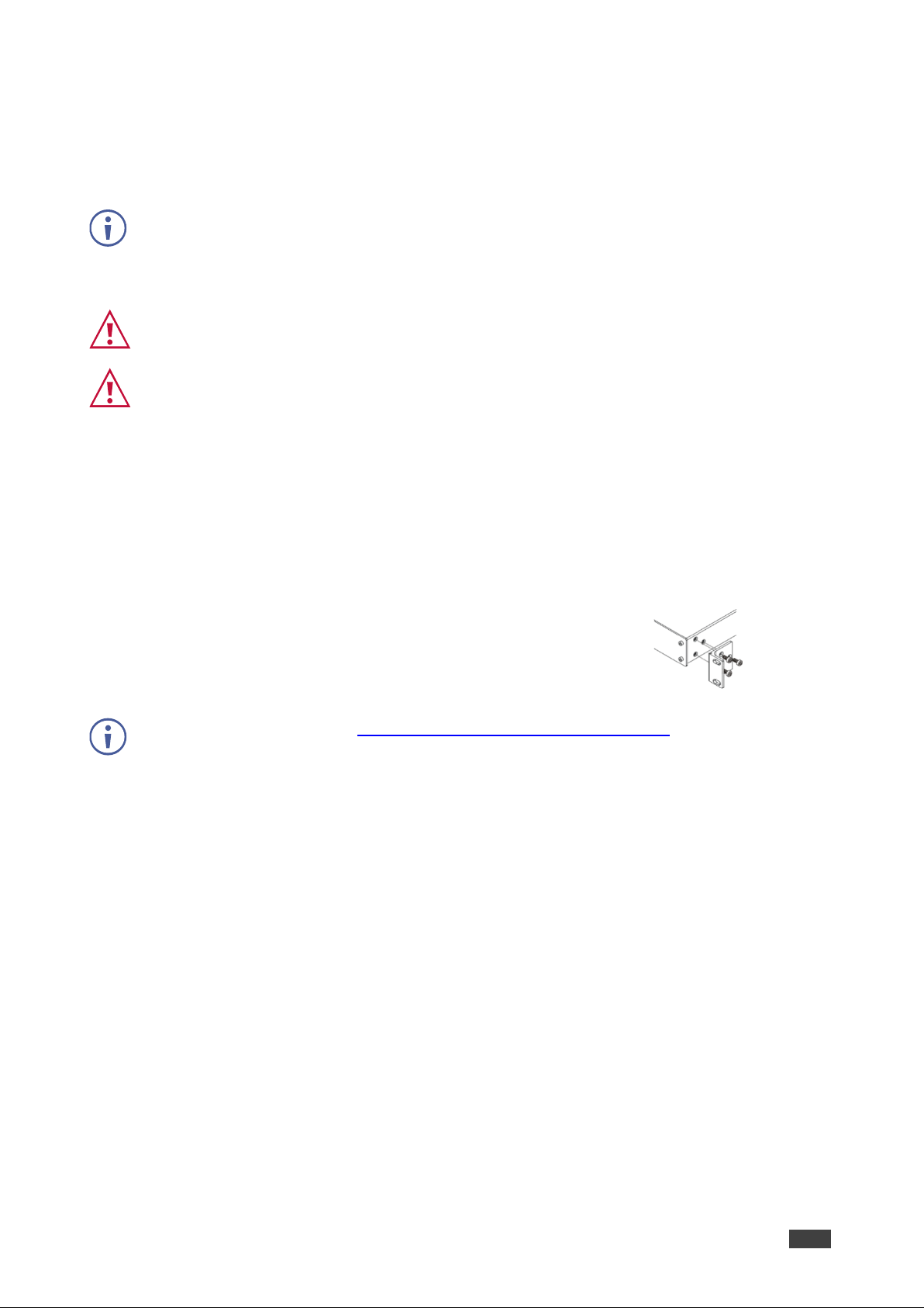
To mount the VP-551X on a rack
Attach both rack ears by removing the screws from each side of the
machine and replacing those screws through the rack ears or place
the machine on a table.
For more information go to www.kramerav.com/downloads/VP-551X
Page 9
Kramer Electronics Ltd.
VP-551X – Connecting VP-551X
7
Connecting VP-551X
Always switch off the power to each device before connecting it to your VP-551X. After
connecting your VP-551X, connect its power and then switch on the power to each device.
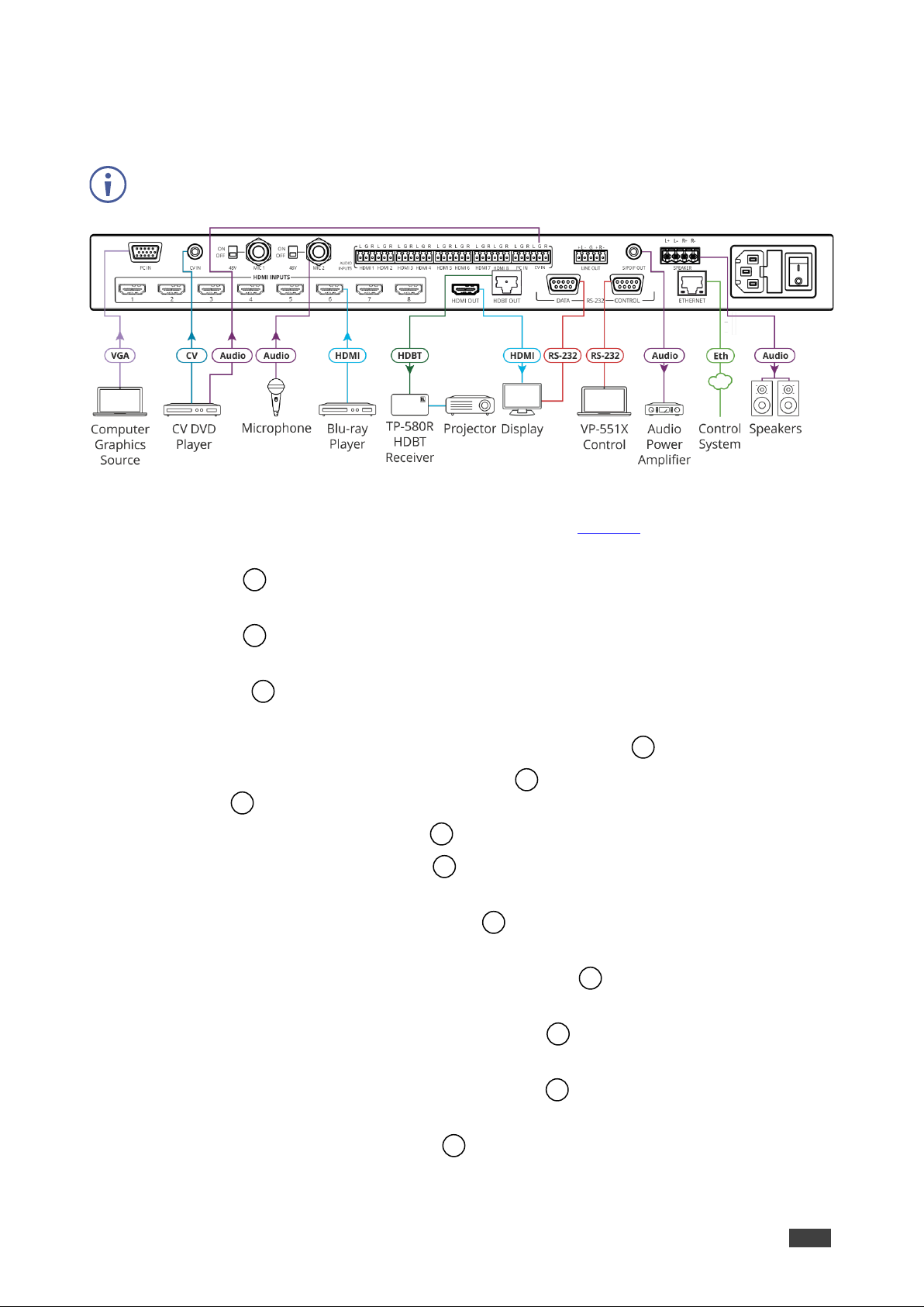
Figure 3: Connecting to the VP-551X Rear Panel
To connect the VP-551X as illustrated in the example in Figure 3:
1. Connect a computer graphics source (for example, a laptop) to the 15-pin HD Input
connector .
2. Connect a composite video source (for example, a DVD player) to the CV RCA
connector .
3. Connect up to 8 HDMI sources (for example, a Blu-ray player to HDMI 5) to the HDMI
connectors .
4. Connect up to 10 balanced audio sources (for example, the PC audio source to the CV
IN AUDIO INPUT) to the AUDIO IN terminal block connectors .
5. Connect a microphone to the MIC 2 6mm jack and set the 48V switch on or off, as
required .
6. Connect the HDMI OUT connector to an acceptor (for example, a display).
7. Connect the HDBT OUT connector to an acceptor (for example, Kramer TP-580R
receiver that is connected to a projector).
8. Connect the S/PDIF OUT RCA connector to a digital audio acceptor (for example,
an audio power amplifier).
9. Connect the SPEAKER 4-pin terminal block connector to speakers (for example,
Kramer Yarden 6-O speakers).
10. Connect the RS-232 DATA 9-pin D-sub connector to the RS-232 port on the display
to control it.
11. Connect the RS-232 CTRL 9-pin D-sub connector to the RS-232 port on a controller
(for example, a laptop) to control the VP-551X.
12. Connect the ETHERNET RJ-45 port to the Ethernet.
Page 10
Kramer Electronics Ltd.
VP-551X – Connecting VP-551X
8
13. Connect the power cord to the VP-551X mains socket and to the mains electricity
(not shown in Figure 3).
The LINE OUT 5-pin terminal block connector , audio acceptor, and power cord are not
shown in Figure 3.
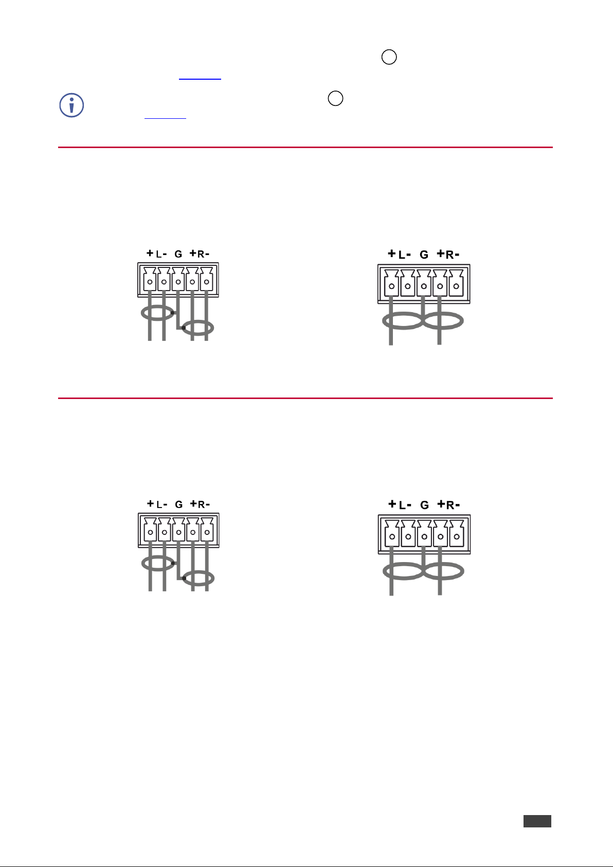
Connecting Output to Balanced/Unbalanced Stereo
Audio Acceptor
The following are the pinouts for connecting the output to a balanced or unbalanced stereo
audio acceptor:
Figure 4: Connecting to a Balanced Stereo Audio
Acceptor
Figure 5: Connecting to an Unbalanced Stereo Audio
Acceptor
Connecting Balanced/Unbalanced Stereo Audio Source to Balanced Input
The following are the pinouts for connecting a balanced or unbalanced stereo audio source to
the balanced input:
Figure 6: Connecting a Balanced Stereo Audio
Source to the Balanced Input
Figure 7: Connecting an Unbalanced Stereo Audio
Source to the Balanced Input
Page 11
Kramer Electronics Ltd.
VP-551X – Connecting VP-551X
9
Microphone Setup
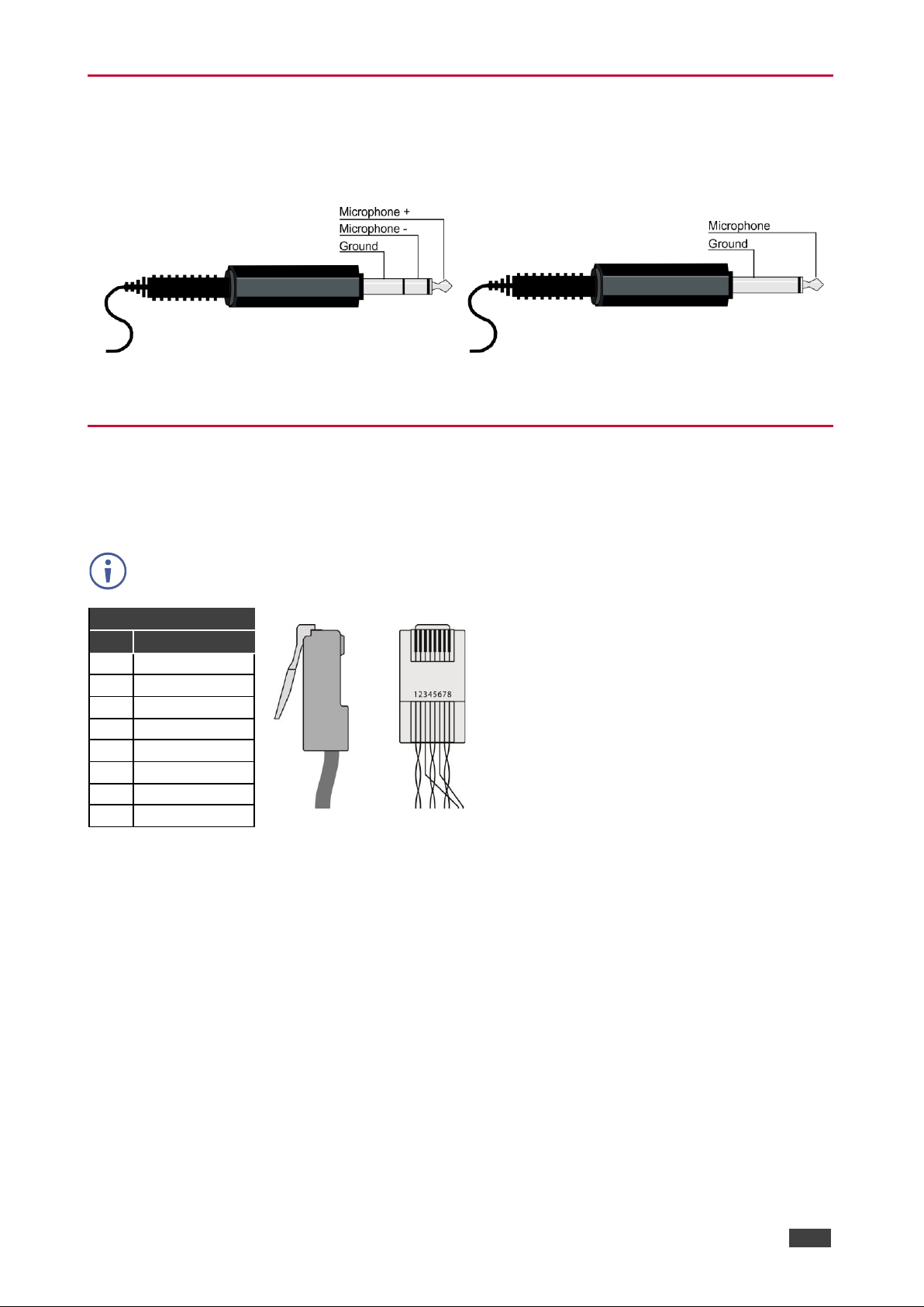
The following are the microphone pinouts.
Condenser Microphone Pinout
Dynamic Microphone Pinout
Figure 8: Condenser Mic Pinout
Figure 9: Dynamic Mic Pinout
Wiring the RJ-45 Connectors
This section defines the HDBaseT pinout, using a straight pin-to -pin cable with RJ-45
connectors.
For HDBT cables, it is recommended that the cable ground shielding be connected/soldered
to the connector shield.
EIA /TIA 568B
PIN
Wire Color
1
Orange / White
2
Orange
3
Green / White
4
Blue
5
Blue / White
6
Green
7
Brown / White
8
Brown
Page 12

Kramer Electronics Ltd.
VP-551X – Operating and Controlling VP-551X
10
Operating and Controlling VP551X
Using Front Panel Buttons
Press the VP-551X front panel buttons to:
• Select the required INPUT (HDMI, PC or CV).
• Freeze and/or mute the output.
• Reset the resolution to XGA/1080p.
• Lock / Unlock the front panel buttons (see Locking and Unlocking Front Panel Buttons
on page 10).
• Control the device via the OSD menu, using the MENU, ENTER, and navigation buttons
(see Controlling Device Via OSD Menu on page 11).
Locking and Unlocking Front Panel Buttons
The front panel buttons can be locked (disabled) to prevent unintentional pressing of the
buttons. Locking modes are set via the Advanced webpage (see Defining Lock Mode
on page 45) or the ADVANCED OSD menu (see Setting Lock Mode Functionality
on page 18).
Locking Procedure
The locking procedure is the same for all locking modes.
To lock the front panel buttons:
• Press and hold PANEL LOCK for about 3 seconds.
The Panel Lock button lights blue and the front panel buttons are locked.
Unlocking Procedure
Unlocking procedure is specific for locking modes.
To unlock the front panel buttons:
• For All or Menu Only Lock modes – Press and hold PANEL LOCK for about 3
seconds.
• For All & Save or Menu Only & Save Lock modes – Press and hold PANEL LOCK
and RESET TO XGA/1080P simultaneously for about 3 seconds.
The Panel Lock button light goes out and the front panel buttons are unlocked.
Page 13

Kramer Electronics Ltd.
VP-551X – Operating and Controlling VP-551X
11
Controlling Device Via OSD Menu
Use the OSD buttons to control the VP-551X via the OSD menu (for more information,
see Navigating OSD Buttons on page 11).
The default OSD timeout is set to 10 seconds.
Use the OSD menu to perform the following operations:
• Setting Image Parameters on page 12.
• Selecting the Input Signal on page 12.
• Setting Output Parameters on page 13.
• Setting the Audio Source on page 14.
• Setting OSD Parameters on page 15.
• Managing EDID on page 16.
• Setting HDCP on page 16.
• Setting Sleep Mode on page 17.
• Setting Switching Mode on page 17.
• Setting Ethernet Parameters on page 17.
• Setting Lock Mode Functionality on page 18.
• Setting Daily Reset Schedule on page 18.
• Viewing Device Hours. on page 18.
• Viewing Device Information on page 19.
• Performing Factory Reset on page 19.
Navigating OSD Buttons
To enter and use the OSD menu buttons:
1. Press MENU.
2. Press:
▪ ENTER to accept changes and to change the menu settings.
▪ Arrow buttons to move through the OSD menu, which is displayed on the video
output.
▪ EXIT to exit the menu.
Page 14
Kramer Electronics Ltd.
VP-551X – Operating and Controlling VP-551X
12
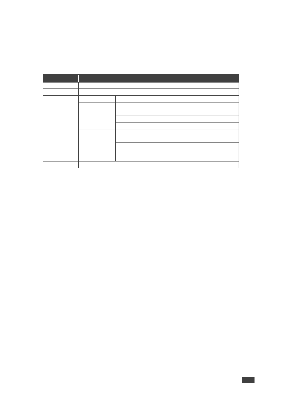
Setting Image Parameters
To set the image parameters:
1. On the front panel press MENU. The menu appears.
2. Click Picture and define the image parameters according to the information in the
following table:
Menu Item
Function
Contrast
Set the contrast.
Brightness
Set the brightness.
Finetune
Input Signal
Function
PC
Phase – set the phase of the sampling clock.
Clock – set the frequency of the sampling clock.
H-Position – set the horizontal picture position.
V-Position – set the vertical picture position.
Video
HUE – set the color hue.
Saturation – set the color saturation.
Sharpness – set the sharpness of the picture.
NR (Noise Reduction) – select the noise reduction filter:
Off (default), Low, Middle or High.
Color
Set the Red, Green and Blue shades.
Selecting the Input Signal
To set the input source:
1. On the front panel press MENU. The menu appears.
2. Click Input and select the input source:
▪ HDMI 1(default) to HDMI 8.
▪ PC.
▪ CV.
Page 15
Kramer Electronics Ltd.
VP-551X – Operating and Controlling VP-551X
13
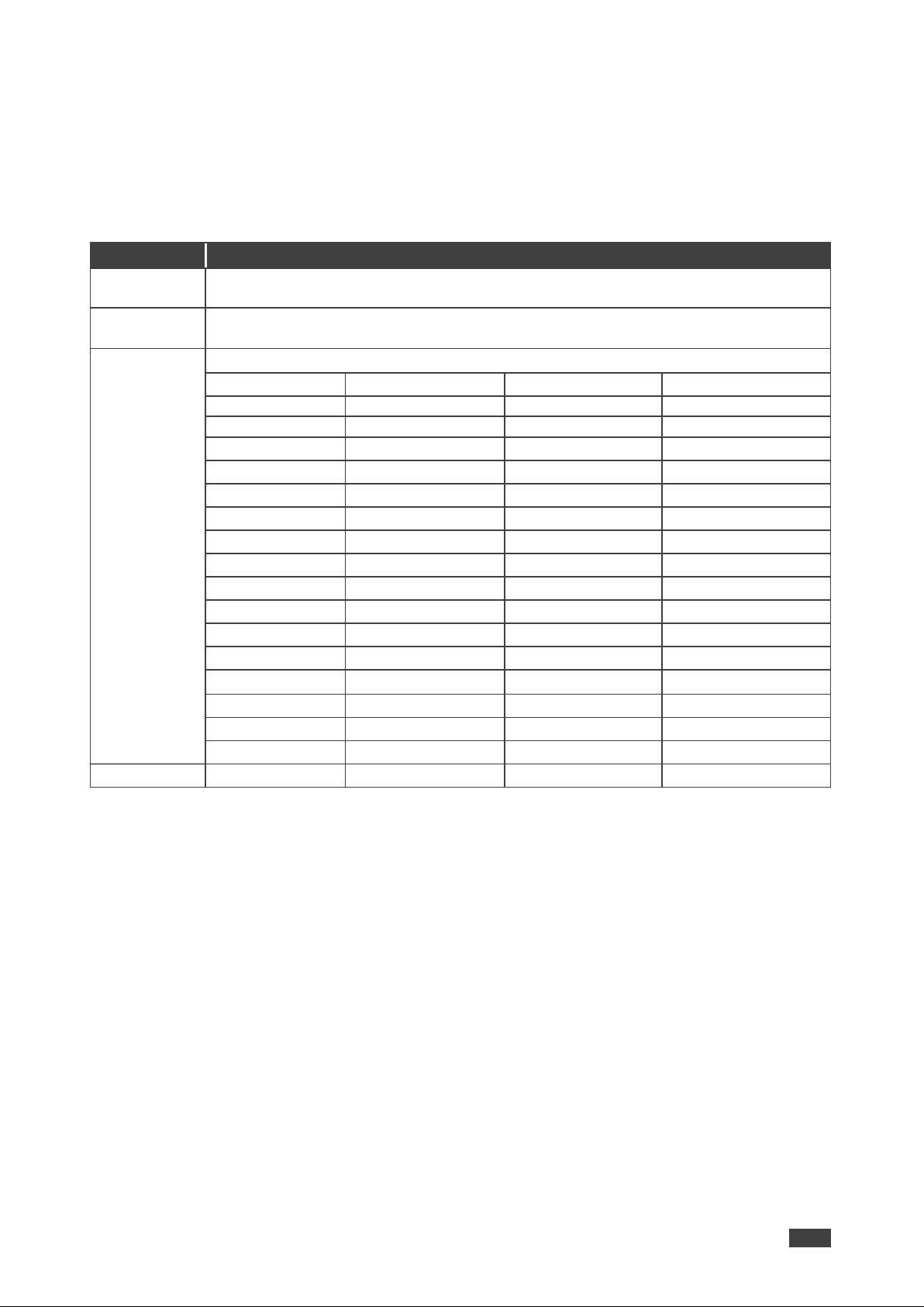
Setting Output Parameters
To set the output parameters:
1. On the front panel press MENU. The menu appears.
2. Click Output and define the output parameters according to the information in the
following table:
Menu Item
Function
Size
Set the size of the image: Full, Overscan, Under 1, Under 2, Letterbox, Panscan, Best fit
(default), Follow In.
Bypass mode
(4Kin->4Kout)
Yes (Bypass): Select for 4K HDMI signals to bypass the scaler (no video processing).
No (Scaler): Select to always scale the HDMI signals.
Resolution
Select the output resolution (default, NATIVE HDMI):
Appears as
Output Resolution
Appears as
Output Resolution
640x480 60
640x480 @60Hz
800x600 60
800x600 @60Hz
1024x768 60
1024x768 @60Hz
1280x768 60
1280x768 @60Hz
1280x800 60
1280x800 @60Hz
1280x1024 60
1280x1024 @60Hz
1360x768 60
1360x768 @60Hz
1400x1050 60
1400x1050 @60Hz
1440x900 60
1440x900 @60Hz
1600x1200 60
1600x1200 @60Hz
1680x1050 60
1680x1050 @60Hz
1920x1200 60 RB
1920x1200 @60Hz RB
2560x1600 60 RB
2560x1600 @60Hz RB
1920x1080 60
1920x1080 @60Hz
1280x720 60
1280x720 @60Hz
2560x1440 60 RB
2560x1440 @60Hz RB
720x480P 60
720x480P @60Hz
720x576P 50
720x576P @50Hz
1280x720P 50
1280x720P @50Hz
1280x720P 60
1280x720P @60Hz
1920x1080P 24
1920x1080P @24Hz
1920x1080P 25
1920x1080P @25Hz
1920x1080P 30
1920x1080P @30Hz
1920x1080P 50
1920x1080P @50Hz
1920x1080P 60
1920x1080P @60Hz
2560x1080P 50
2560x1080P @50Hz
2560x1080P 60
2560x1080P @60Hz
3840x2160P 24
3840x2160P @24Hz
3840x2160P 25
3840x2160P @25Hz
3840x2160P 30
3840x2160P @30Hz
3840x2160P 50(420)
4k2k @50Hz (4:2:0)
3840x2160P 60(420)
4k2k @60Hz (4:2:0)
For HDMI only
3840x2160P 50
3840x2160P @50Hz
3840x2160P 60
3840x2160P @60Hz
Page 16
Kramer Electronics Ltd.
VP-551X – Operating and Controlling VP-551X
14
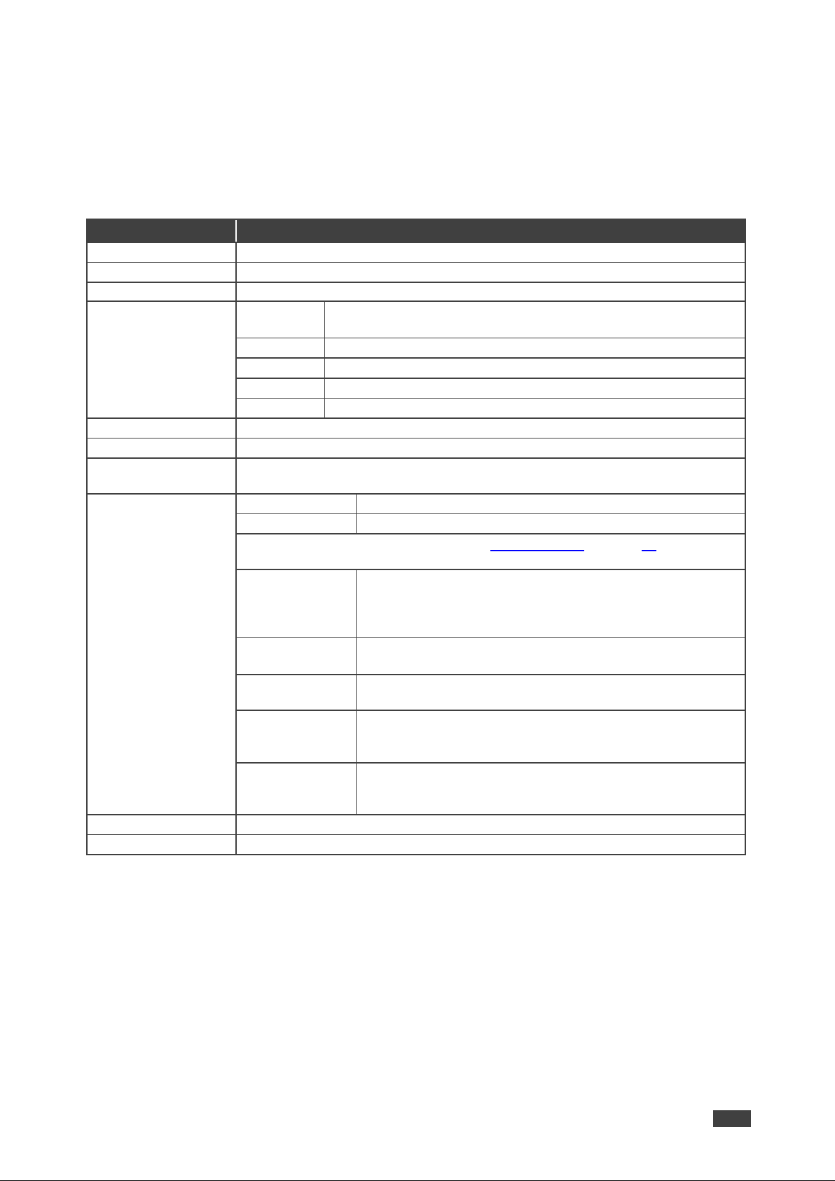
Setting the Audio Source
To set the audio source:
1. On the front panel press MENU. The menu appears.
2. Click Audio and define the audio parameters according to the information in the
following table:
Menu Item
Function
Input Volume
Set the analog audio input volume for HDMI 1 to HDMI 8, PC and CV.
Output Volume
Set the LINE OUT output volume
Speaker Volume
Set the SPEAKER volume.
Setting
Delay
Set the audio delay time to 40ms (default),50ms, 60ms to 200ms
(in 10ms steps).
DRC
Set dynamic range compression Off (default) or On.
Bass
Set the output bass level.
Treble
Set the output treble level.
Loudness
Set loudness Off (default) or On.
Mute
Set audio mute to Off (default) or On.
Speaker Mute
Set audio speaker mute to Off (default) or On.
Source
Set each HDMI input (1 to 8) audio source to Automatic (default), Analog or
Embedded.
Mic Settings
Mic Mode
Set to Off (default), Mixer, Talkover or Mic Only.
Mic Select
Set to Mic 1 (default), Mic 2 or Both.
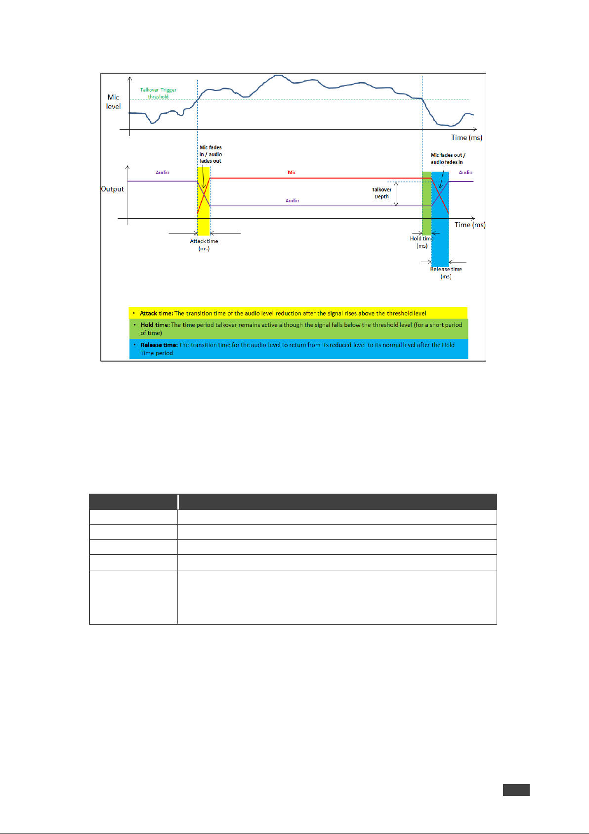
When Mic Mode is set to Talkover (see Talkover Mode on page 15), set the
following:
Depth [%]
Set the depth value to determine the decrease of the audio
level during microphone takeover (press + to further
decrease the talkover audio output level; press – to lessen
the talkover output audio decrease level).
Trigger [dB]
Set the trigger value to determine the microphone threshold
level that triggers the audio output level decrease.
Attack Time
Set the attack time to set the transition time of the audio level
reduction after the signal rises above the threshold level.
Hold Time
Set the hold time to define the time period talkover remains
active although the signal falls below the threshold level (for
a short period of time).
Release Time
Set the release time to define the transition time for the
audio level to return from its reduced level to its normal level
after the Hold Time period.
Mic Volume
Set microphone volume (MIC 1, MIC 2).
Embedded In -> Out
Apply DSP (default) to the embedded audio or ByPass it.
Page 17
Kramer Electronics Ltd.
VP-551X – Operating and Controlling VP-551X
15
Talkover Mode
Figure 10: Talkover Mode
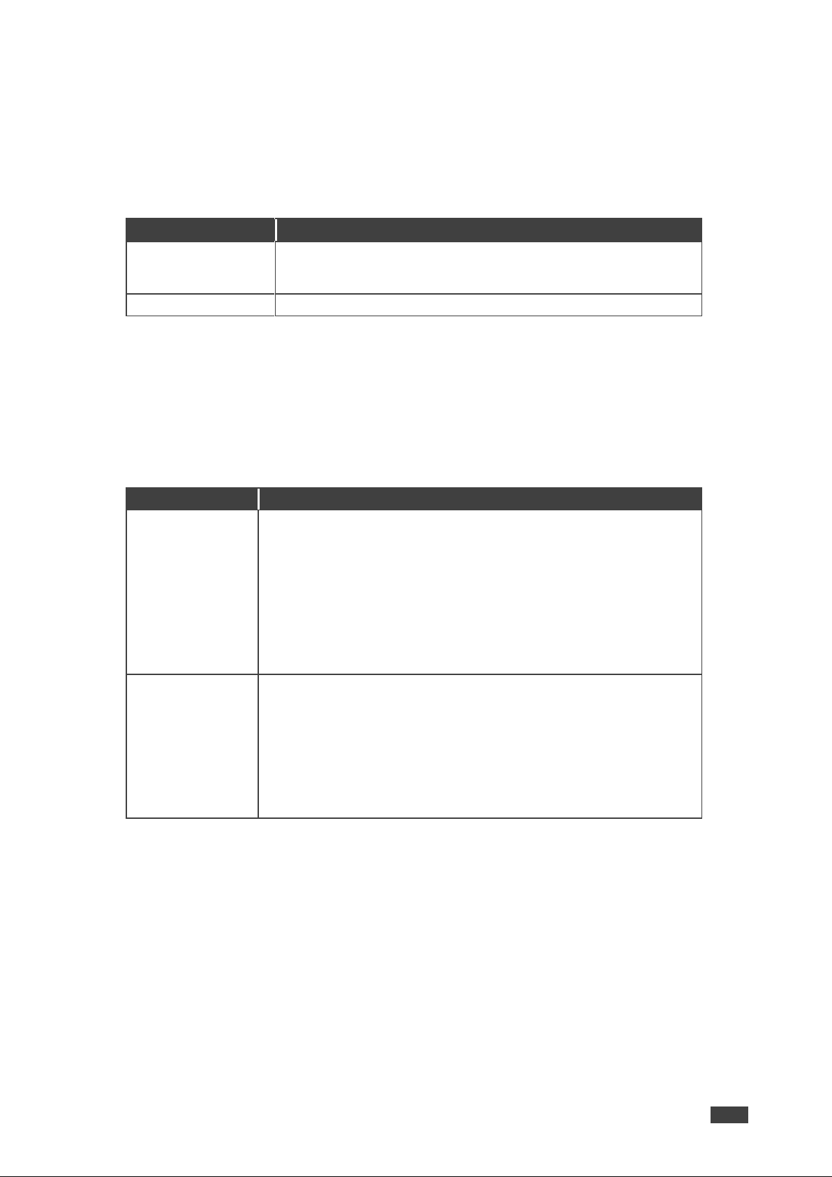
Setting OSD Parameters
To set the OSD parameters:
1. On the front panel press MENU. The menu appears.
2. Click OSD and define the OSD parameters according to the information in the following
table:
Menu Item
Function
H-Position
Set the horizontal position of the OSD.
V-Position
Set the vertical position of the OSD.
Timer
Set the timeout period to Off or up to 60 seconds (default 10).
Transparency
Set the OSD background between 100 (transparent) and 0 (opaque).
Display
Select the information displayed on-screen during operation:
Info (default) – the information appears for 10 seconds.
On – the information appears constantly.
Off – the information does not appear.
Page 18
Kramer Electronics Ltd.
VP-551X – Operating and Controlling VP-551X
16
Managing EDID
To manage the EDID:
1. On the front panel press MENU. The menu appears.
2. Click EDID Manage and define the EDID parameters according to the information in the
following table:
Menu Item
Function
EDID on HDMI (1 to 8)
For each HDMI input, select a built-in EDID and press enter:
Def.1080P (default), Def. 4K(3G), Def. 4K(4:2:0), Def. 4K(6G),
HDMI Output or HDBT Output.
EDID on PC
Default
Setting HDCP
To set the HDCP on the inputs and output:
1. On the front panel press MENU. The menu appears.
2. Click Advanced and define the HDCP parameters according to the information in the
following table:
Menu Item
Function
HDCP On Input
Set HDCP support on HDMI 1 to HDMI 8 inputs to ON (default) or
OFF.
Note that:
1. HDCP must be enabled (ON) in order to support HDCP
encrypted sources.
2. Sources such as Mac computers always encrypt their outputs
when detecting that the sink supports HDCP. If the content
does not require HDCP, you can prevent these sources from
encrypting by disabling (OFF) HDCP on the input.
HDCP On Output
Select Follow Output (default) or Follow Input on each output (HDMI
OUT and HDBT OUT).
Select Follow Output (recommended) for the scaler to match its HDCP
output to the HDCP setting of the HDMI/HDCP acceptor to which it is
connected.
Select Follow Input to change its HDCP output setting according to
the HDCP of the input (recommended when the HDMI/HDCP output is
connected to a splitter/switcher).
Page 19
Kramer Electronics Ltd.
VP-551X – Operating and Controlling VP-551X
17
Setting Sleep Mode
VP-551X enables configuring if and when a connected display enters sleep mode using the
Auto Sync Off feature. Auto Sync Off turns off the output after a period of not detecting a valid
video signal on the input(s) until a valid input is again detected or any keypad is pressed.
To set the Auto Sync Off:
1. On the front panel press MENU. The menu appears.
2. Click ADVANCED and select Auto Sync Off.
3. Define Auto Sync Off according to the information in the following table:
Menu Item
Function
Disable (default)
To leave outputs active at all times.
Slow
To disable outputs after ~ 2 minutes of no input detection.
Fast
To disable outputs after ~ 10 seconds of no input detection.
Immediate
To disable outputs ~ 0.5 seconds after detecting a loss of input signal.
Setting Switching Mode
To set the switching mode:
1. On the front panel press MENU. The menu appears.
2. Click Advanced and select Auto Switching.
3. Select the switching mode according to the information in the following table:
Menu Item
Function
Off (default)
For manual switching.
Auto Scan
Scans for a valid input when no signal is found on the selected input.
Last Connected
Automatically switches to the last connected input and reverts back
to the last selected input after that input is lost.
Setting Ethernet Parameters
To set the Ethernet :
1. On the front panel press MENU. The menu appears.
2. Click Advanced and define the Ethernet parameters according to the information in the
following table:
Menu Item
Function
IP Mode
Select Static IP (default) or DHCP.
Static IP Address
Enter to change the IP address.
Subnet Mask
Enter to change the subnet mask.
Default Gateway
Enter to change the default gateway.
TCP Port
Enter TCP port # (5000, by-default).
UDP Port
Enter UDP port # (50000, by-default).
IP
View the current IP address.
MAC ADDRESS
View the MAC address.
Link Status
View the link status.
Page 20
Kramer Electronics Ltd.
VP-551X – Operating and Controlling VP-551X
18
Setting Lock Mode Functionality
To set the functionality of the LOCK front panel button:
1. On the front panel press MENU. The menu appears.
2. Click Advanced and select Lock Mode.
3. Set a panel lock mode according to the information in the following table:
Menu Item
Function
All
All front panel buttons are locked.
All & Save
All front panel buttons are locked and remain locked after cycling power.
Menu Only
Menu buttons are locked.
Menu & Save
Menu buttons are locked and remain locked after cycling power.
To unlock the front panels, see Locking and Unlocking Front Panel Buttons on page 10.
Setting Daily Reset Schedule
For units operating 24/7, the Daily Reset Timer may be used to automatically reset the unit
each day.
Note that this function reboots the unit – it does not reset any of the parameters.
To set a daily reset schedule:
1. On the front panel press MENU. The menu appears.
2. Click Advanced and select Daily Reset.
3. Set the daily reset schedule.
Menu Item
Function
Daily Reset
Disable daily reset (Off, default) or enable daily reset (On).
Next Reset (h)
Set the number of hours before
the next reset.
Set f or the “Next Reset” to fix the time
that the unit will be reset each day.
Next Reset (m)
Set the number of minutes
before the next reset.
After Power-Up
Define behavior following a power cycle:
Disable – The Daily Reset Timer is turned off.
Restart – The timer restarts when the unit is powered up (i.e., from then
onwards, the unit resets each day at the time that the unit is powered up).
Resume – The timer continues running after power returns (while
powered down, the timer does not run).
Viewing Device Hours.
Lifetime shows the total number of hours that the machine has been in operation.
To view device hours:
1. On the front panel press MENU. The menu appears.
2. Click Advanced.
3. View Lifetime and view device hours.
Page 21

Kramer Electronics Ltd.
VP-551X – Operating and Controlling VP-551X
19
Viewing Device Information
Device information includes the selected source, the input and output resolutions, and the
software version.
To view the information:
1. On the front panel press MENU. The menu appears.
2. Click Info and view the following information:
Performing Factory Reset
To perform factory reset:
1. On the front panel press MENU. The menu appears.
2. Click Factory and select either Reset (full reset) or a Soft Reset (excluding Ethernet
parameters), then click Yes.
Wait for completion of factory reset (resolution is set to Native).
Operating via Ethernet
You can connect to the VP-551X via Ethernet using either of the following methods:
• Directly to the PC using a crossover cable (see (see Connecting the Ethernet Port
Directly to a PC on page 19).
• Via a network hub, switch, or router, using a straight-through cable (see Connecting the
Ethernet Port via a Network Hub or Switch on page 21).
If you want to connect via a router and your IT system is based on IPv6, speak to your IT
department for specific installation instructions.
For info on configuring the Ethernet, see Changing Ethernet Settings on page 29.
Connecting the Ethernet Port Directly to a PC
You can connect the Ethernet port of the VP-551X directly to the Ethernet port on your PC
using a crossover cable with RJ-45 connectors.
This type of connection is recommended for identifying the VP-551X with the factory
configured default IP address.
After connecting the VP-551X to the Ethernet port, configure your PC as follows:
1. Click Start > Control Panel > Network and Sharing Center.
2. Click Change Adapter Settings.
3. Highlight the network adapter you want to use to connect to the device and click
Change settings of this connection.
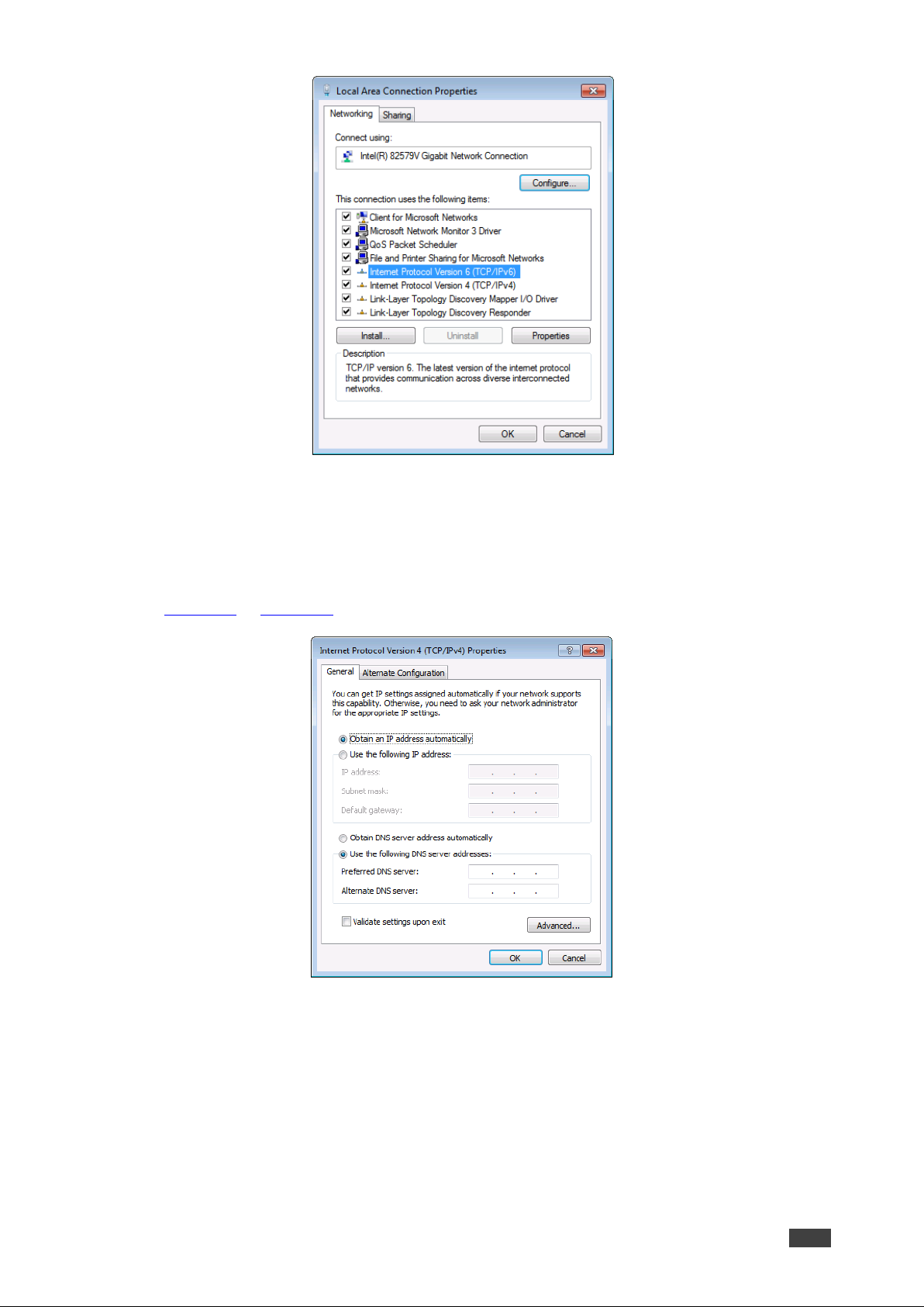
The Local Area Connection Properties window for the selected network adapter appears
as shown in Figure 11.
Page 22
Kramer Electronics Ltd.
VP-551X – Operating and Controlling VP-551X
20
Figure 11: Local Area Connection Properties Window
4. Highlight either Internet Protocol Version 6 (TCP/IPv6) or Internet Protocol Version
4 (TCP/IPv4) depending on the requirements of your IT system.
5. Click Properties.
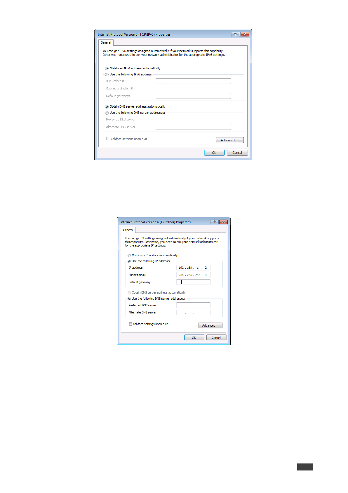
The Internet Protocol Properties window relevant to your IT system appears as shown in
Figure 12 or Figure 13.
Figure 12: Internet Protocol Version 4 Properties Window
Page 23
Kramer Electronics Ltd.
VP-551X – Operating and Controlling VP-551X
21
Figure 13: Internet Protocol Version 6 Properties Window
6. Select Use the following IP Address for static IP addressing and fill in the details as
shown in Figure 14.
For TCP/IPv4 you can use any IP address in the range 192.168.1.1 to 192.168.1.255
(excluding 192.168.1.39) that is provided by your IT department.
Figure 14: Internet Protocol Properties Window
7. Click OK.
8. Click Close.
Connecting the Ethernet Port via a Network Hub or Switch
You can connect the Ethernet port of the VP-551X to the Ethernet port on a network hub or
using a straight-through cable with RJ-45 connectors.
Page 24
Kramer Electronics Ltd.
VP-551X – Using the Embedded Webpages
22
Using the Embedded Webpages
The VP-551X can be operated remotely using the embedded webpages. The webpages are
accessed using a Web browser and an Ethernet connection.
Before attempting to connect:
• Perform the procedures in Operating via Ethernet on page 19.
• Ensure that your browser is supported.
The following operating systems and Web browsers are supported:
Operating Systems
Versions
Windows 7
IE Firefox
Chrome
Safari
Windows 10
IE
Edge
Firefox
Chrome
Mac
Safari
iOS
Safari
Some features might not be supported by some cellphone operating systems.
Browsing VP-551X Webpages
To browse the VP-551X webpages:
1. Open your Internet browser.
2. Type the IP Address of the device in the Address bar of your browser. For example, the
default IP Address:
Page 25
Kramer Electronics Ltd.
VP-551X – Using the Embedded Webpages
23
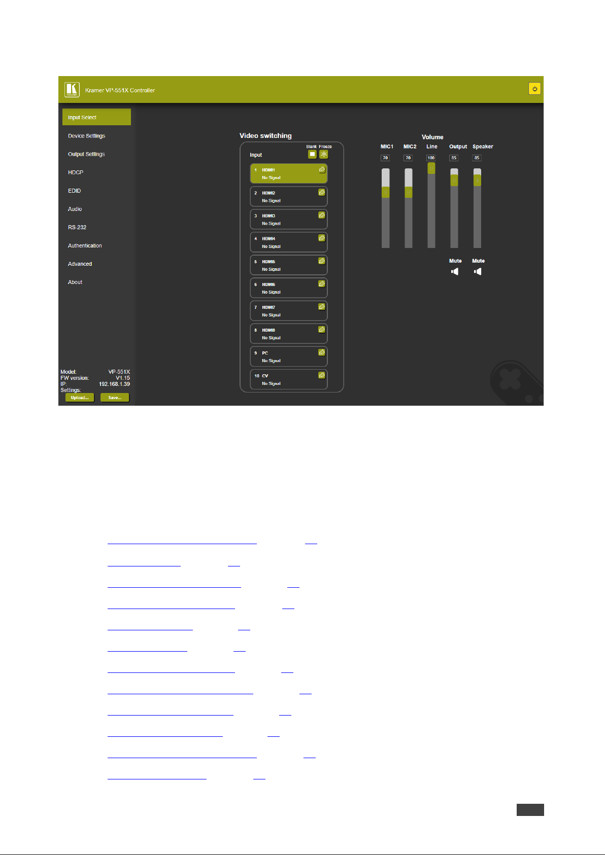
The Input Select webpage appears.
Figure 15: VP-551X Input Select Page with Navigation List on Left
The model name, FW version and IP Address appear on the lower left side of the main
page. The lower part of the screen lets you save the settings and upload a saved
setting.
3. Click the desired item in the navigation pane.
The VP-551X webpage enables performing the following functions:
• Browsing VP-551X Webpages on page 22.
• Selecting Input on page 24.
• Setting Device Parameters on page 27.
• Changing Output Settings on page 30.
• Managing HDCP on page 33.
• Managing EDID on page 34.
• Setting Audio Parameters on page 35.
• Setting RS-232 Port Function on page 37.
• Setting Webpage Access on page 41.
• Defining Auto Sync Off on page 44.
• Defining Auto Switching Mode on page 45.
• Defining Lock Mode on page 45.
Page 26

Kramer Electronics Ltd.
VP-551X – Using the Embedded Webpages
24
• System Maintenance on page 46.
• Viewing Device Information on page 47.
Selecting Input
Use the Input Select page to configure the inputs, route an input to one or more outputs, and
set the mic and output volumes.
The Input Select page enables performing the following functions:
• Video Switching on page 25.
• Editing an Input on page 26.
• Setting the Volume on page 27.
Page 27
Kramer Electronics Ltd.
VP-551X – Using the Embedded Webpages
25
Video Switching
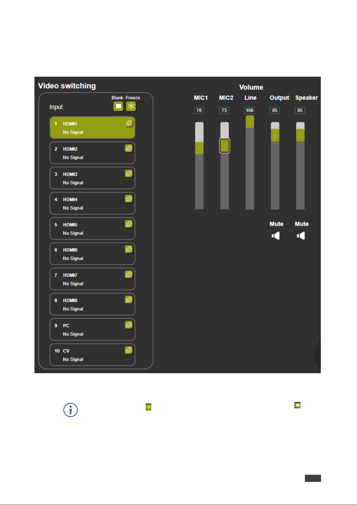
To select an input to route to the output:
1. In the Navigation pane, click Input Select. The Input Select page appears.
Figure 16: Input Select Page
2. Click an HDMI button. The selected input is routed to both outputs.
Use the freeze icon ( ) to freeze a selected input and the blank button ( ) to
display a blank image.
Page 28
Kramer Electronics Ltd.
VP-551X – Using the Embedded Webpages
26
Editing an Input
To edit an input button:
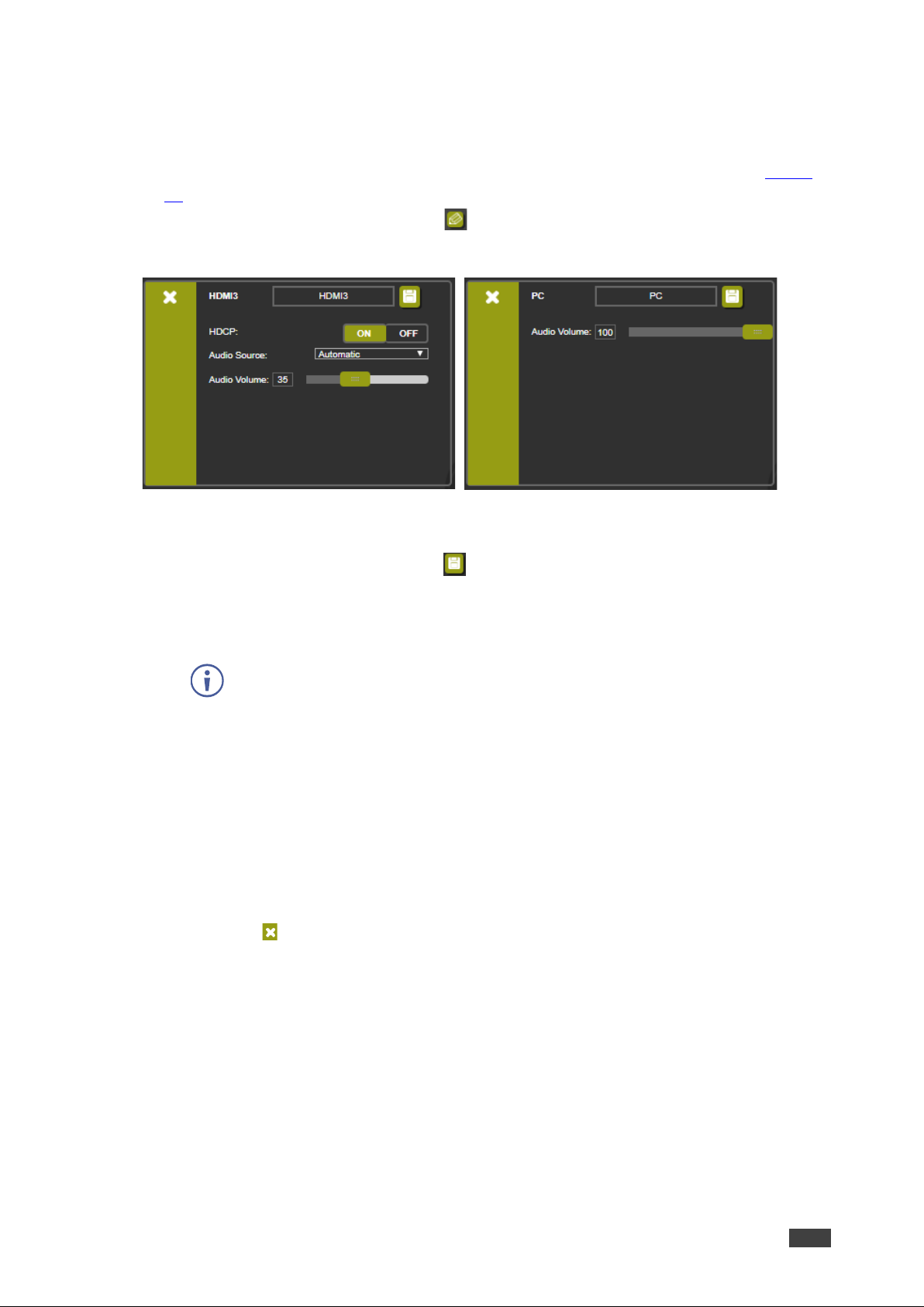
1. In the Navigation pane, click Input Select. The Input Select page appears (see Figure
16).
2. In the Video switching area, click the button in an HDMI/CV/PC button to edit that
input.
Figure 17: Input Select Page – Editing an Input Button
3. Edit the following features:
▪ Change the input name and click .
▪ Set the input Audio Volume.
▪ For HDMI inputs only, set the HDCP on the input to ON or OFF.
If HDCP is disabled on an input, an HDCP encrypted source will not pass
through the unit.
▪ For HDMI inputs only, select an analog or embedded audio source or set input audio
selection to automatic:
Automatic – The embedded audio on the HDMI input is selected for an HDMI
signal, or the analog audio input is selected if the input is not HDMI (for example,
for a DVI input signal).
Analog – The analog audio input is selected.
Embedded – The embedded audio in the HDMI signal is selected.
4. To exit, click .
Page 29

Kramer Electronics Ltd.
VP-551X – Using the Embedded Webpages
27
Setting the Volume
To set the mic and output volumes:
1. In the Navigation pane, click Input Select. The Input Select page appears
(see Figure 16).
2. Use the Volume sliders to adjust:
▪ MIC 1 /MIC 2 microphone volume.
▪ Line (the selected input) volume.
▪ Output (LINE OUT and S/PDIF OUT ) volume.
▪ Speaker volume.
You can also set a specific volume by entering the volume value in the text box above a
slider and pressing Enter on your PC.
3. Click the Mute icon to mute line / speaker audio signal.
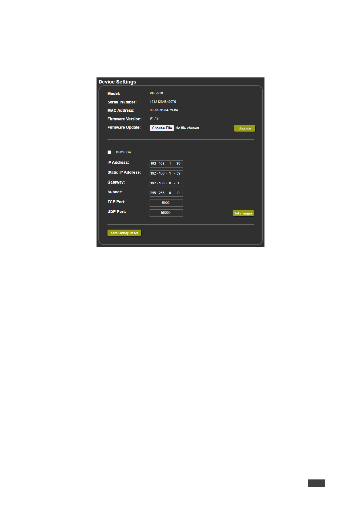
Setting Device Parameters
The Device Settings page shows the model name, its serial number and MAC address as
well as its current firmware version.
The Device Settings page enables performing the following functions:
• Updating the Firmware on page 28.
• Changing Ethernet Settings on page 29.
• Soft Factory Reset on page 30.
Page 30
Kramer Electronics Ltd.
VP-551X – Using the Embedded Webpages
28
Updating the Firmware
To update the firmware:
1. In the Navigation pane, click Device Settings. The Device Settings page appears.
Figure 18: Device Settings Page
2. Click Choose File. An Open window appears.
3. Select the correct firmware file.
4. Click Open. The selected file appears in the Firmware Update field.
5. Click Upgrade.
The new firmware is uploaded, the firmware is upgraded and the system restarts.
Upon completion, the webpage refreshes.
Page 31
Kramer Electronics Ltd.
VP-551X – Using the Embedded Webpages
29
Changing Ethernet Settings
To change Ethernet parameters:
1. In the Navigation pane, click Device Settings. The Device Settings page appears (see
Figure 18):
2. Check/uncheck the DHCP box ON or OFF (default).
When DHCP is checked, Static IP Address, gateway and Subnet are disabled.
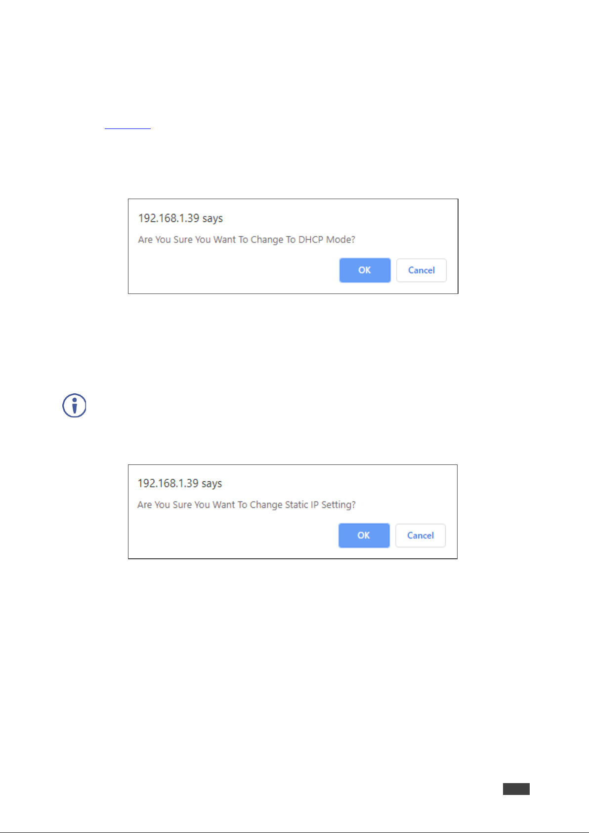
3. Click Set changes. The following message appears.
Figure 19: Device Settings Page – Changing DHCP Mode
4. Click OK.
5. If DHCP is OFF, change any of the parameters (IP Address, Netmask and/or Gateway).
6. Click Set Changes.
• After changing the IP Address, or DHCP to ON, the webpage reloads with the new IP
address.
• After changing the Subnet mask, turn the VP-551X power off and then on again.
Any change in the device settings requires confirmation.
Figure 20: Device Settings Page – Static IP Confirmation
7. Click OK.
Ethernet parameters are changed.
Page 32
Kramer Electronics Ltd.
VP-551X – Using the Embedded Webpages
30
Soft Factory Reset
To reset the device to its factory default parameters (except for the Ethernet
parameters):
1. In the Navigation pane, click Device Settings. The Device Settings page appears.
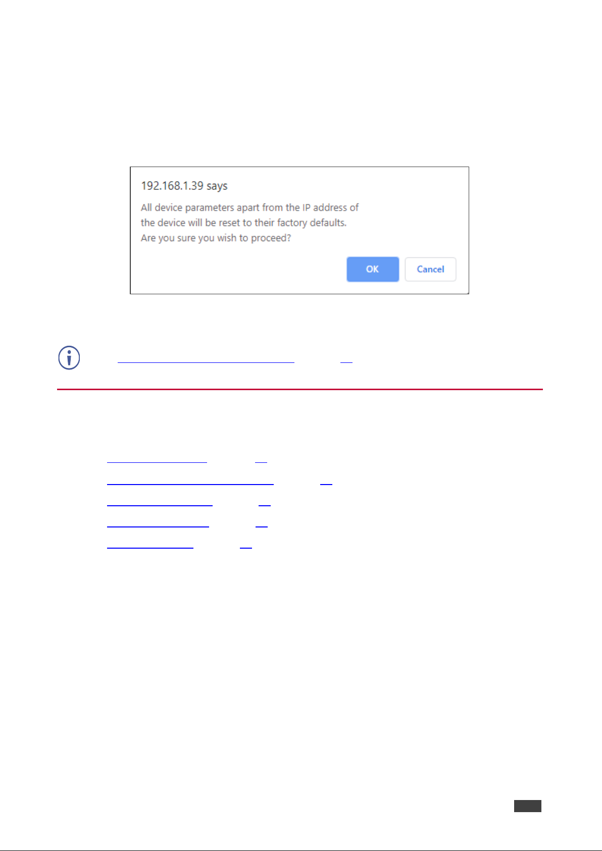
2. Click Soft Factory reset the following message appears:
Figure 21: Device Settings Page – Factory Reset Message
3. Click OK and wait for the webpage to reload following factory reset.
See Default Communication Parameters on page 51 to view other factory reset procedures.
Changing Output Settings
VP-551X enables performing the following functions on the outputs:
• Selecting Resolution on page 31.
• Setting Image Size on the Display on page 31.
• Setting Bypass Mode on page 31.
• Adjusting the Picture on page 32.
• Finetuning Image on page 32.
Page 33
Kramer Electronics Ltd.
VP-551X – Using the Embedded Webpages
31
Selecting Resolution
To select the resolution:
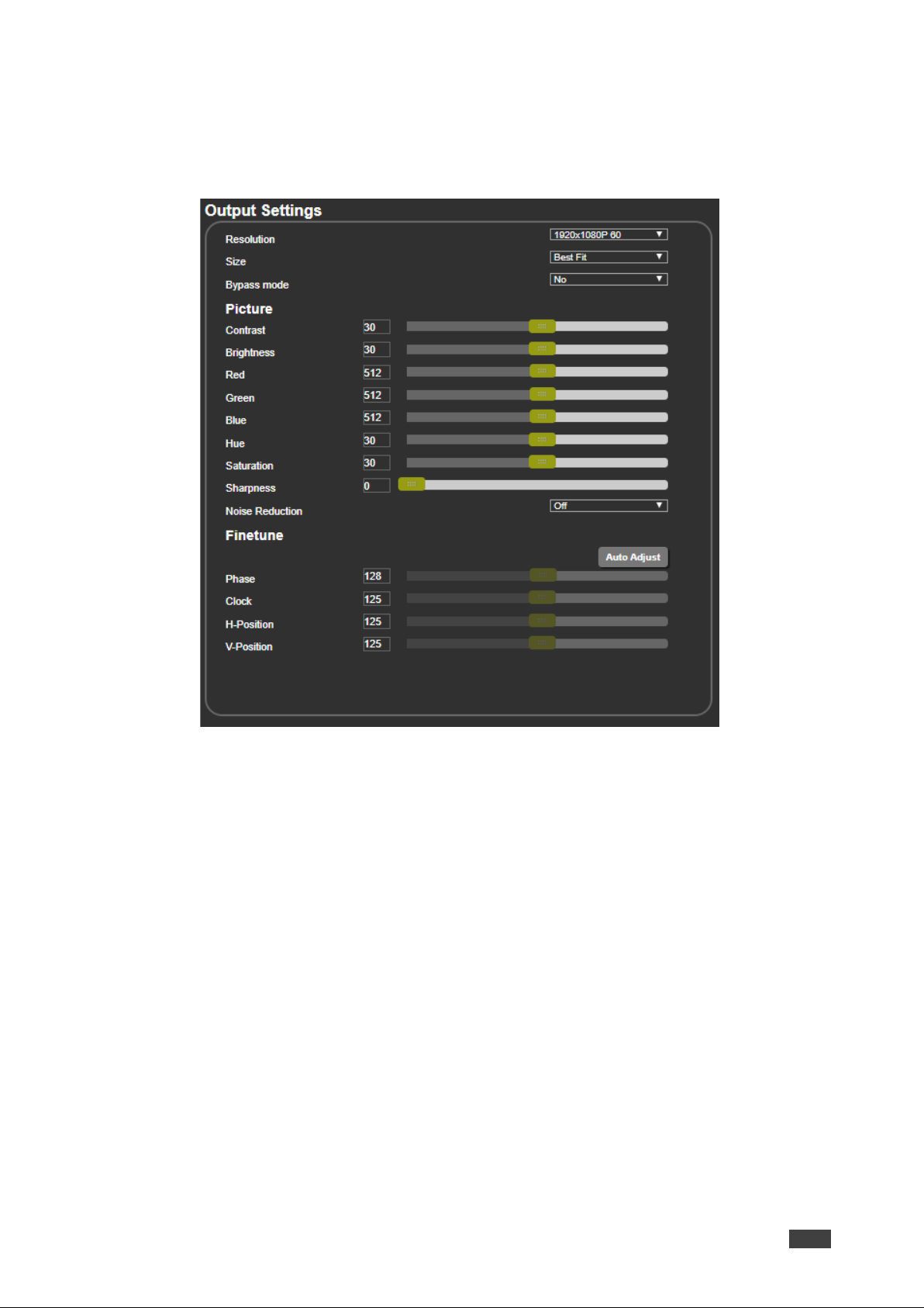
1. In the Navigation pane, click Device Settings. The Device Settings page appears.
Figure 22: Output Settings Page
2. Open the drop-down box next to Resolution to select the output resolution.
Output resolution is selected.
Setting Image Size on the Display
To set the image size:
1. In the Navigation pane, click Output Settings. The Device Settings page appears.
2. Open the drop-down box next to Size to set the image size.
Setting Bypass Mode
To set bypass mode:
1. In the Navigation pane, click Output Settings. The Device Settings page appears.
2. Open the drop-down box next to Bypass to set the bypass mode to:
▪ On – Process the HDMI signal via the scaler.
▪ Off – No video processing (scaler is bypassed).
Page 34
Kramer Electronics Ltd.
VP-551X – Using the Embedded Webpages
32
Adjusting the Picture
The picture parameters can be adjusted depending on the input type.
To Adjust the picture:
1. In the Navigation pane, click Output Settings. The Device Settings page appears.
2. Use the sliders under Picture to adjust contrast, brightness, colors (red, green and blue),
Hue Saturation and sharpness.
For HDMI and CV inputs all picture adjustments are available for the PC input, hue,
saturation and sharpness are disabled.
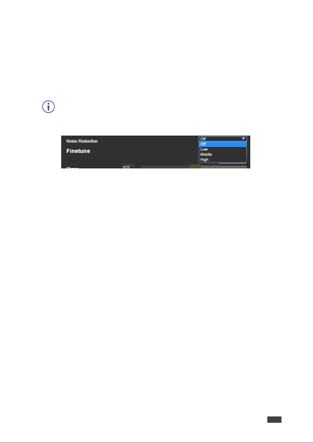
3. Open the Noise Reduction drop-down box to define noise reduction.
Figure 23: Output Settings Page – Noise Reduction
Finetuning Image
If the PC input is selected, you can fine tune the image.
To finetune the image:
1. In the Navigation pane, click Output Settings. The Output Settings page appears.
2. Click Auto Adjust to automatically adjust the image.
3. Use the sliders to adjust the phase, clock, H-Position and V-Position.
Page 35
Kramer Electronics Ltd.
VP-551X – Using the Embedded Webpages
33
Managing HDCP
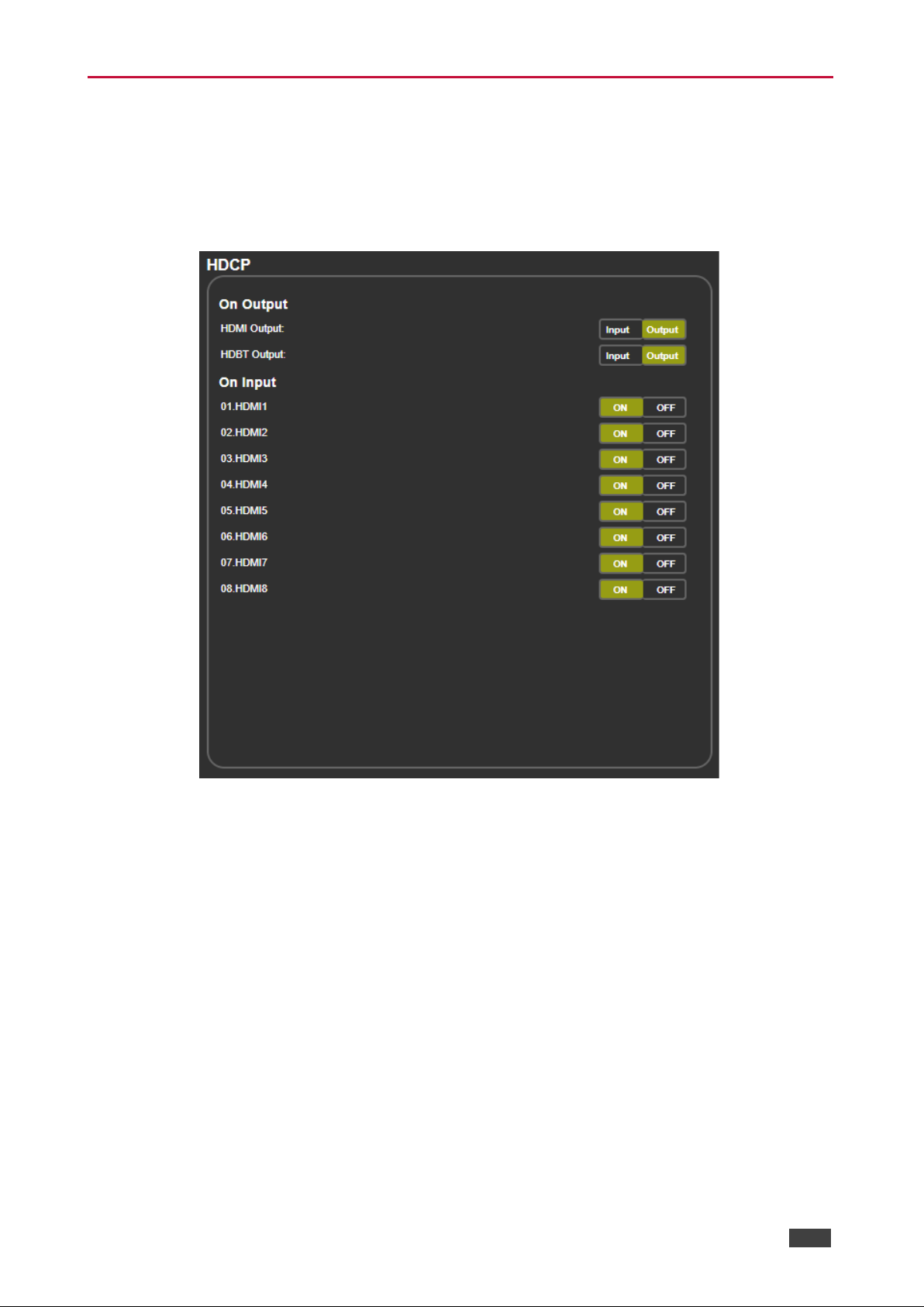
Use the HDCP page to define the encryption on the input and outputs.
To manage HDCP:
1. In the Navigation pane, click HDCP. The HDCP page appears.
Figure 24: HDCP Page
2. Perform the following actions:
▪ Set the HDMI output to follow Input or Output.
▪ Set the HDBT output to follow Input or Output.
▪ Set HDCP on each HDMI input separately to ON or OFF.
Page 36
Kramer Electronics Ltd.
VP-551X – Using the Embedded Webpages
34
Managing EDID
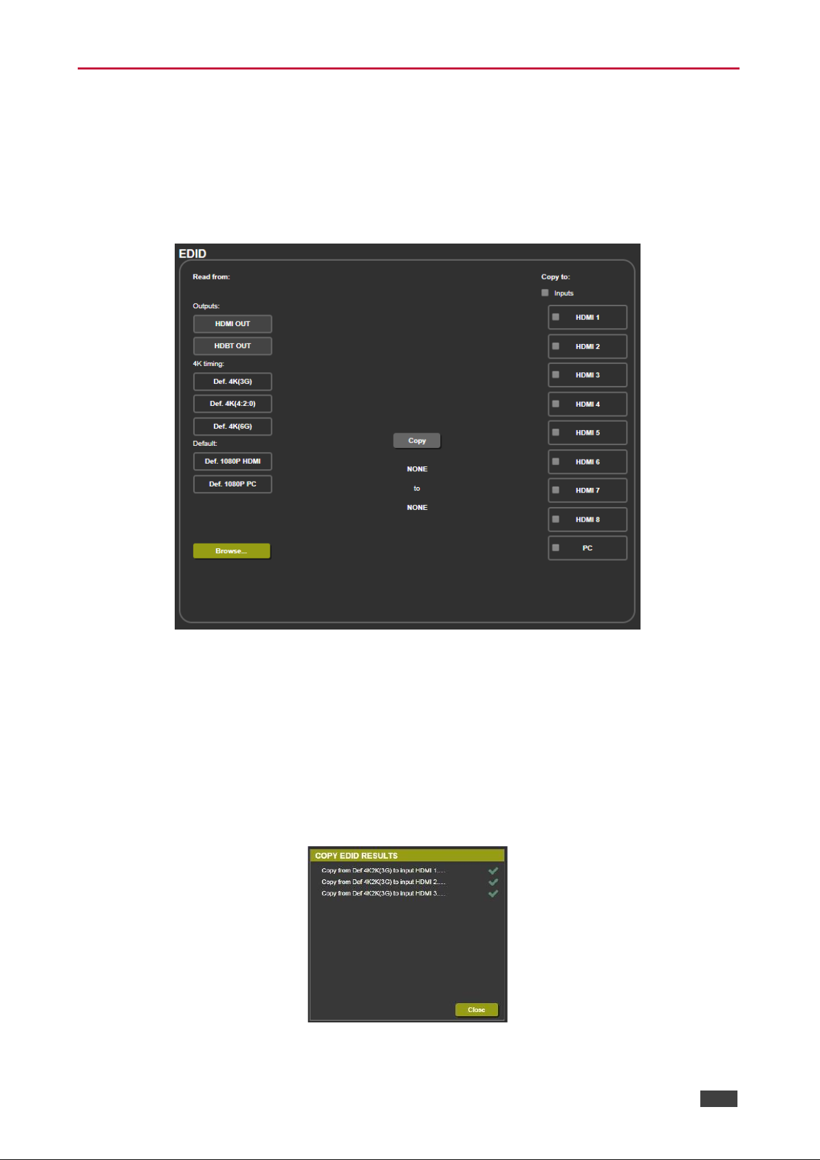
Acquire the EDID from the outputs (HDMI or HDBT), 4K timing or from defaults for HDMI or
PC.
To acquire EDID:
1. In the Navigation pane, click EDID. The EDID page appears.
Figure 25: EDID Page
2. In the Read from area on the left, click the required EDID source (outputs, timing, or
defaults) or click Browse to use an external EDID configuration File.
3. In the Copy to area on the right, click the input(s) to which to copy the selected EDID.
The Copy button is enabled.
4. Click Copy.
The selected EDID is copied to the selected inputs and the Copy EDID Results
message appears.
Figure 26: EDID Page –Copy EDID Results
5. Click Close.
Page 37
Kramer Electronics Ltd.
VP-551X – Using the Embedded Webpages
35
Setting Audio Parameters
VP-551X enables setting the audio delay time and performing the following functions:
• Setting Input Source and Volume on page 35.
• Adjusting Microphone Settings on page 36.
• Configuring Additional Audio Settings on page 36.
To set the microphone and output volumes, see Setting the Volume on page 27.
Setting Input Source and Volume
To set the input volume:
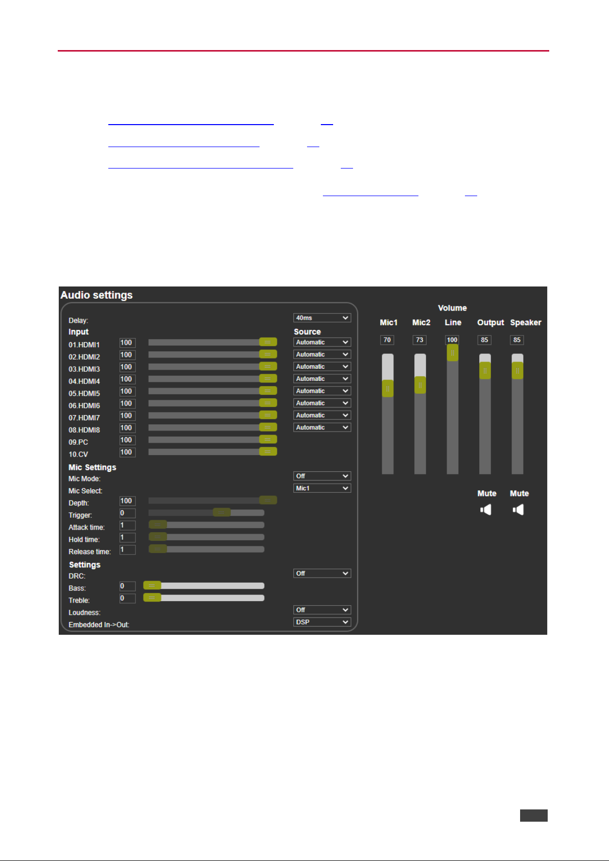
1. In the Navigation pane, click Audio Settings. The Audio Settings page appears.
Figure 27: Audio Settings Page
2. For each input, set the volume by:
▪ Entering the value in the text box next to the input name.
▪ Sliding the volume switch.
The volume is set.
Page 38

Kramer Electronics Ltd.
VP-551X – Using the Embedded Webpages
36
To set the input audio source:
1. In the Navigation pane, click Audio Settings. The Audio Settings page appears (see
Figure 27).
2. For each HDMI input, select the audio source (Automatic, Analog or Embedded) from
the drop-down box.
The input source is selected.
Adjusting Microphone Settings
To adjust microphone settings:
1. In the Navigation pane, click Audio Settings. The Audio Settings page appears (see
Figure 27).
2. Under Mic Settings you can do the following:
▪ Open the Mic Mode drop-down box and select the microphone mode.
▪ Select Mic1, Mic2 or Both.
3. When Mic mode is set to Talkover, set the Depth, Trigger, Attack time, Hold time and
Release time by:
▪ Entering the value in the text box next to the input name.
▪ Sliding the volume switch.
For further details, see Talkover Mode on page 15.
Configuring Additional Audio Settings
You can configure other audio parameters under the Settings area.
To configure additional audio settings:
1. In the Navigation pane, click Audio Settings. The Audio Settings page appears.
2. Under Settings you can do the following:
▪ Set DRC (Dynamic Range Compression) to On or Off (default).
▪ Adjust the Bass and Treble by:
Entering the value in the text box next to the input name.
Sliding the volume switch.
Set Loudness to On or Off (default).
▪ Apply DSP (default) to the embedded audio or Bypass it.
Page 39
Kramer Electronics Ltd.
VP-551X – Using the Embedded Webpages
37
Setting RS-232 Port Function
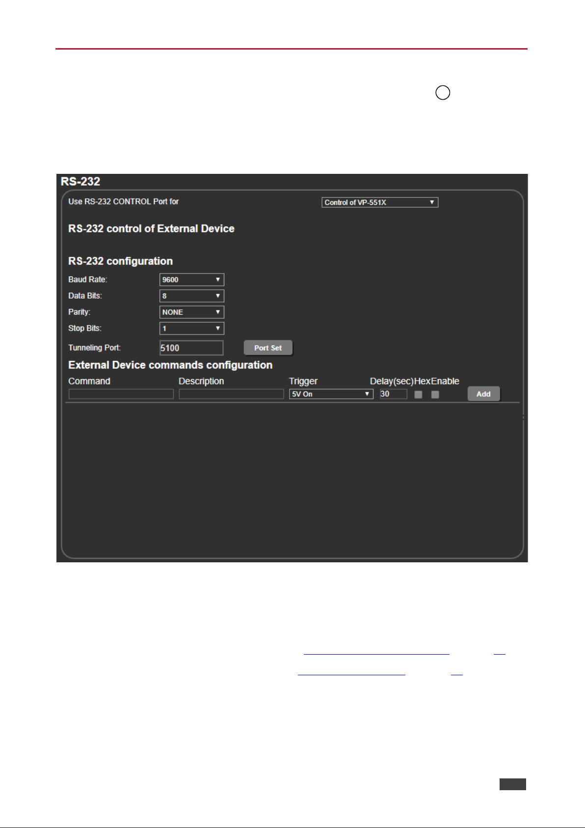
Use the RS-232 page to define the function of the RS-232 CONTROL port on the VP-
551X rear panel.
To set the RS-232 port function:
1. In the Navigation pane, click RS-232. The RS-232 page appears.
Figure 28: RS-232 Page – Control the Device Setting
2. In the Use RS-232 Control Port for drop down list, select one of the port options:
▪ Control of VP-551X – connect a system controller to the RS-232 port to control VP-
551X.
▪ Control of EXTERNAL DEVICE – see Controlling an External Device on page 38.
▪ RS-232 tunneling via Ethernet – see Tunneling via Ethernet on page 40.
Page 40
Kramer Electronics Ltd.
VP-551X – Using the Embedded Webpages
38
Controlling an External Device
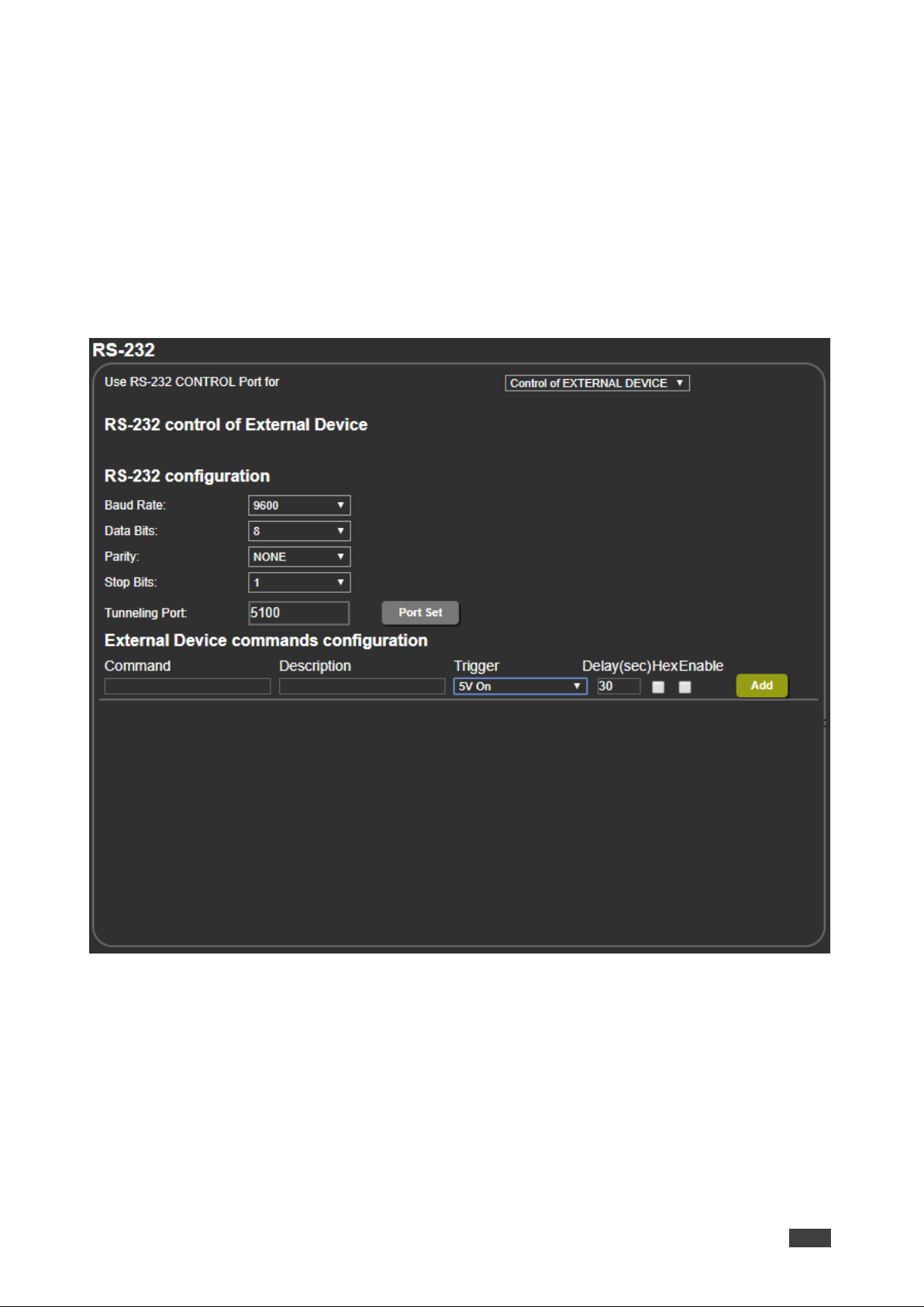
When Control of EXTERNAL DEVICE is selected, you can set VP-551X to automatically
send RS-232 commands to a device (for example, to turn off a projector when no video signal
is detected on the VP-551X input).
To send commands to an external device:
1. In the Navigation pane, click RS-232. The Audio RS-232 page appears.
2. Set RS-232 Control to Control of EXTERNAL DEVICE:
Figure 29: RS-232 Page – Controlling an External Device
3. Under RS-232 Configuration set the RS-232 port parameters to enable communication
with the acceptor.
Page 41
Kramer Electronics Ltd.
VP-551X – Using the Embedded Webpages
39
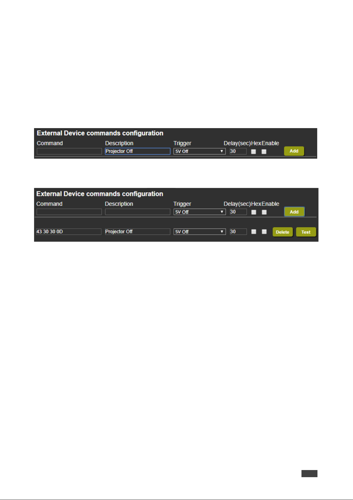
4. Configure the commands as follows:
▪ Enter a device command (for example, turn projector off).
▪ Enter the command description.
▪ Select a trigger from the drop-down box to carry out the command (5V On, 5V Off,
Sync/Clock or No Sync/No Clock).
▪ Enter a delay time, if required.
▪ Check Hex to view the Hex format, if required.
▪ Check enable to enable the command.
Figure 30: RS-232 – Creating a Command
5. Click Add.
Figure 31: RS-232 Page – Command Added
6. Optionally, perform the following for the command:
▪ Click Delete to delete the command.
▪ Click Test to test the command.
▪ Change any of the command configurations.
▪ Enable or disable the command.
Page 42
Kramer Electronics Ltd.
VP-551X – Using the Embedded Webpages
40
Tunneling via Ethernet
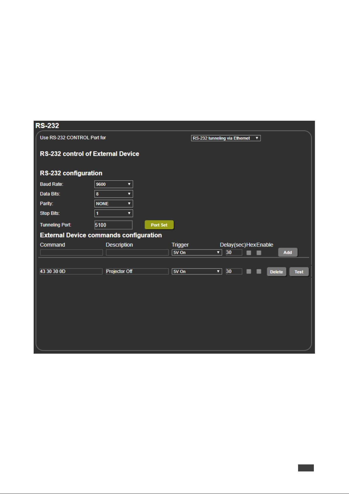
When RS-232 tunneling via Ethernet is selected, you can send commands via Ethernet,
allowing embedded RS-232 data tunneled between the Ethernet port and the RS-232
CONTROL port.
To send commands to the HDMI acceptor:
1. In the Navigation pane, click RS-232. The Audio RS-232 page appears.
2. Set RS-232 Control to RS-232 tunneling via Ethernet:
Figure 32: RS-232 Page – Tunneling via Ethernet
3. Under RS-232 Configuration set the RS-232 port parameters to enable communication
with the acceptor.
4. Enter the Tunneling Port and click Port Set.
Page 43
Kramer Electronics Ltd.
VP-551X – Using the Embedded Webpages
41
Setting Webpage Access
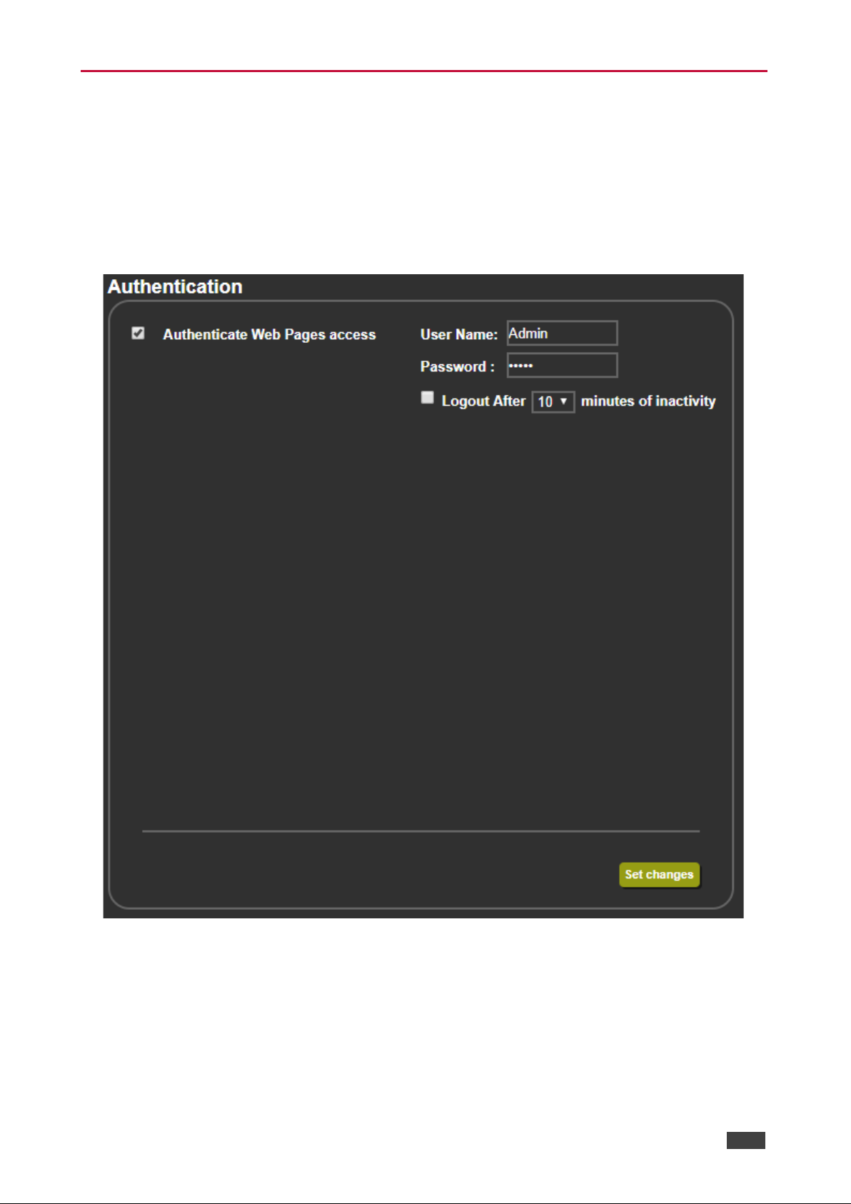
By default, the webpages are secured and require access permission (user name and
password are both: Admin). This section describes how to change the password and
disable/enable access permission.
To change the password:
1. In the Navigation pane, click Authentication. The Authentication page appears.
Figure 33: Authentication Page
2. Enter the new password.
Page 44
Kramer Electronics Ltd.
VP-551X – Using the Embedded Webpages
42
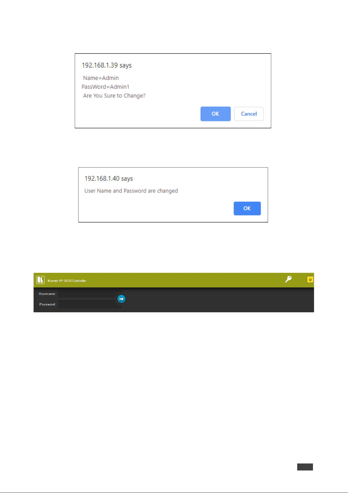
3. Click Set changes.
The following message appears:
Figure 34: Authentication Page – Changing the Name/Password
4. Click OK.
The following message appears:
Figure 35: Authentication Page – Password Change Confirmation
5. Click OK.
Username and password have changed.
6. Reenter the webpages.
Figure 36: Authentication Page – Password Authentication
7. Click arrow.
the webpage reloads.
To disable security:
1. In the Navigation pane, click Authentication. The Authentication page appears.
2. Uncheck Authenticate Web Pages access.
Page 45
Kramer Electronics Ltd.
VP-551X – Using the Embedded Webpages
43
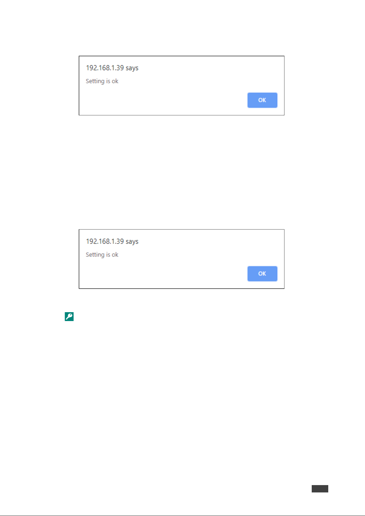
3. Click Set changes
The following message appears:
Figure 37: Authentication Page – Security Disable Confirmation
4. Click OK.
Authentication is not required.
To enable security:
1. In the Navigation pane, click Security. The Security page appears.
2. Check Authenticate Web pages Access.
Previous credentials are restored.
3. Click Set changes.
The following message appears:
Figure 38: Security – Security Enable Confirmation
4. Click OK.
appears, and authentication is now required.
Page 46
Kramer Electronics Ltd.
VP-551X – Using the Embedded Webpages
44
Defining Auto Sync Off
Define auto sync off when signal is lost (also set via the OSD menu, see Setting Sleep Mode
on page 17).
To define auto sync off:
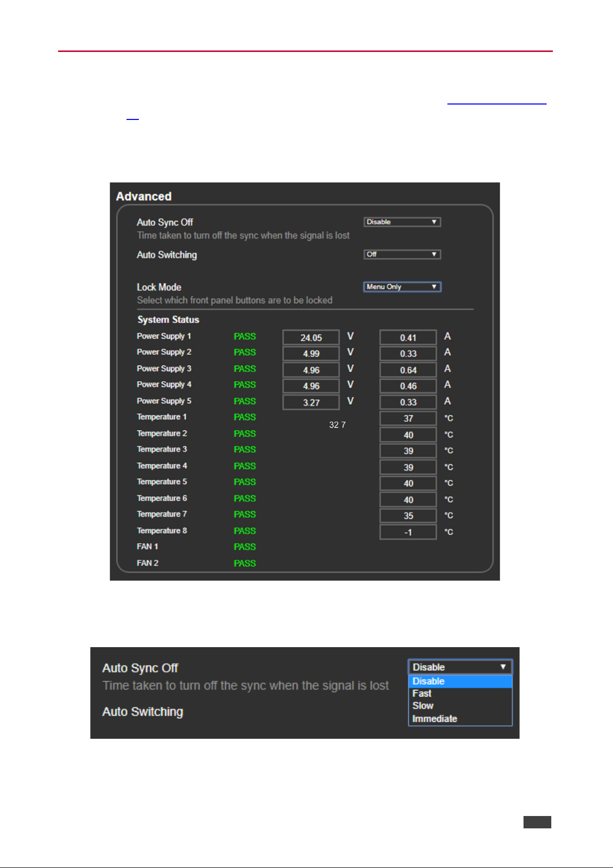
1. In the Navigation pane, click Advanced. The Advanced page appears.
Figure 39: Advanced Page
2. In the Auto Sync Off drop-down box, select the sync mode (Disable, Slow, Fast or
Immediate).
Figure 40: Advanced Page – Defining Auto Sync Off
Auto Sync Off mode is set.
Page 47
Kramer Electronics Ltd.
VP-551X – Using the Embedded Webpages
45
Defining Auto Switching Mode
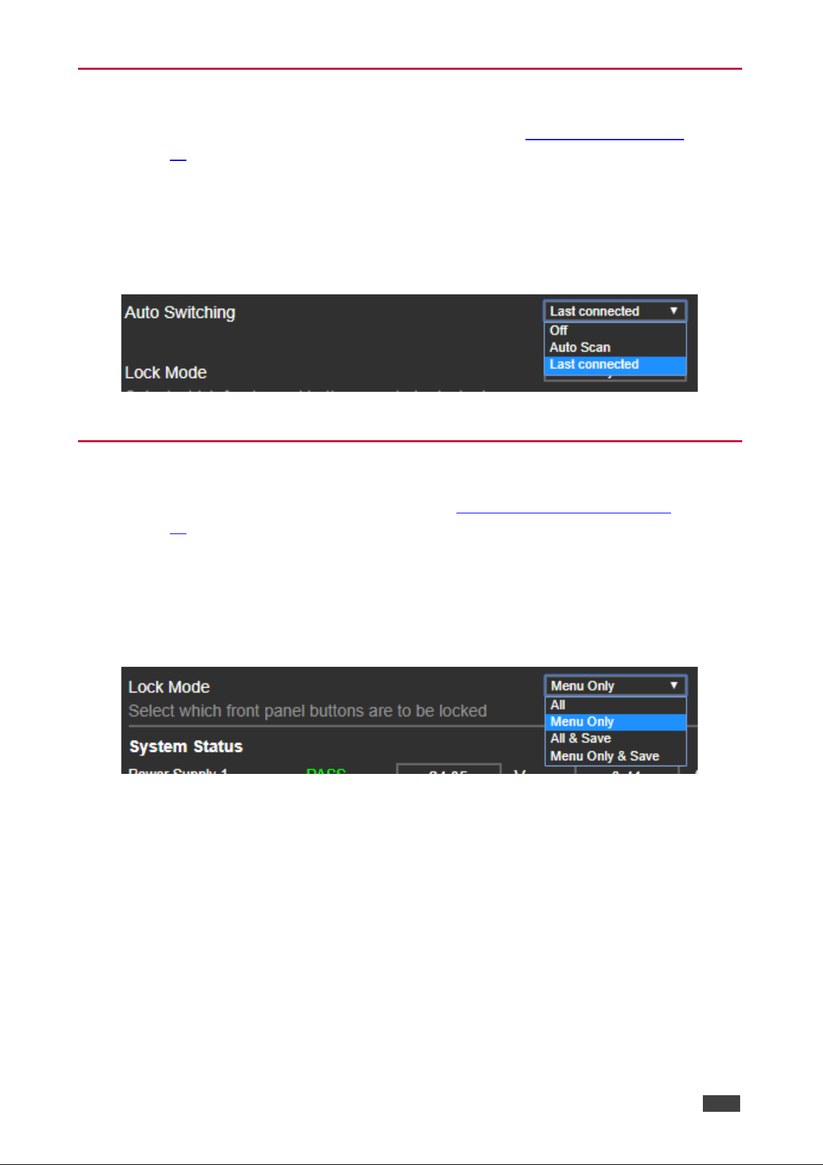
Define auto switching mode (also set via the OSD menu, see Setting Switching Mode
on page 17).
To define auto switching mode:
1. In the Navigation pane, click Advanced. The Advanced page appears.
2. Next to Auto Switching, open the drop-down box to select the switching mode (Off
(manual), Auto Scan or Last Connected).
Figure 41: Advanced Page – Defining Switching Mode
Defining Lock Mode
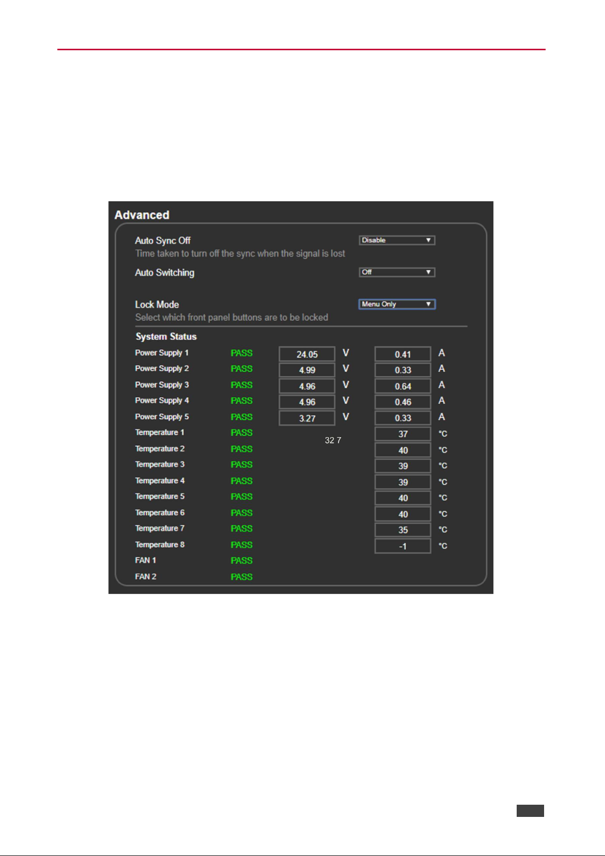
Define lock mode (also set via the OSD menu, see Setting Lock Mode Functionality
on page 18).
To define Lock mode:
1. In the Navigation pane, click Advanced. The Advanced page appears.
2. Next to Lock Mode, open the drop-down box to select the lock mode (All, Menu Only, All
& Save or Menu Only & Save).
Figure 42: Advanced Page – Defining Lock Mode
Page 48
Kramer Electronics Ltd.
VP-551X – Using the Embedded Webpages
46
System Maintenance
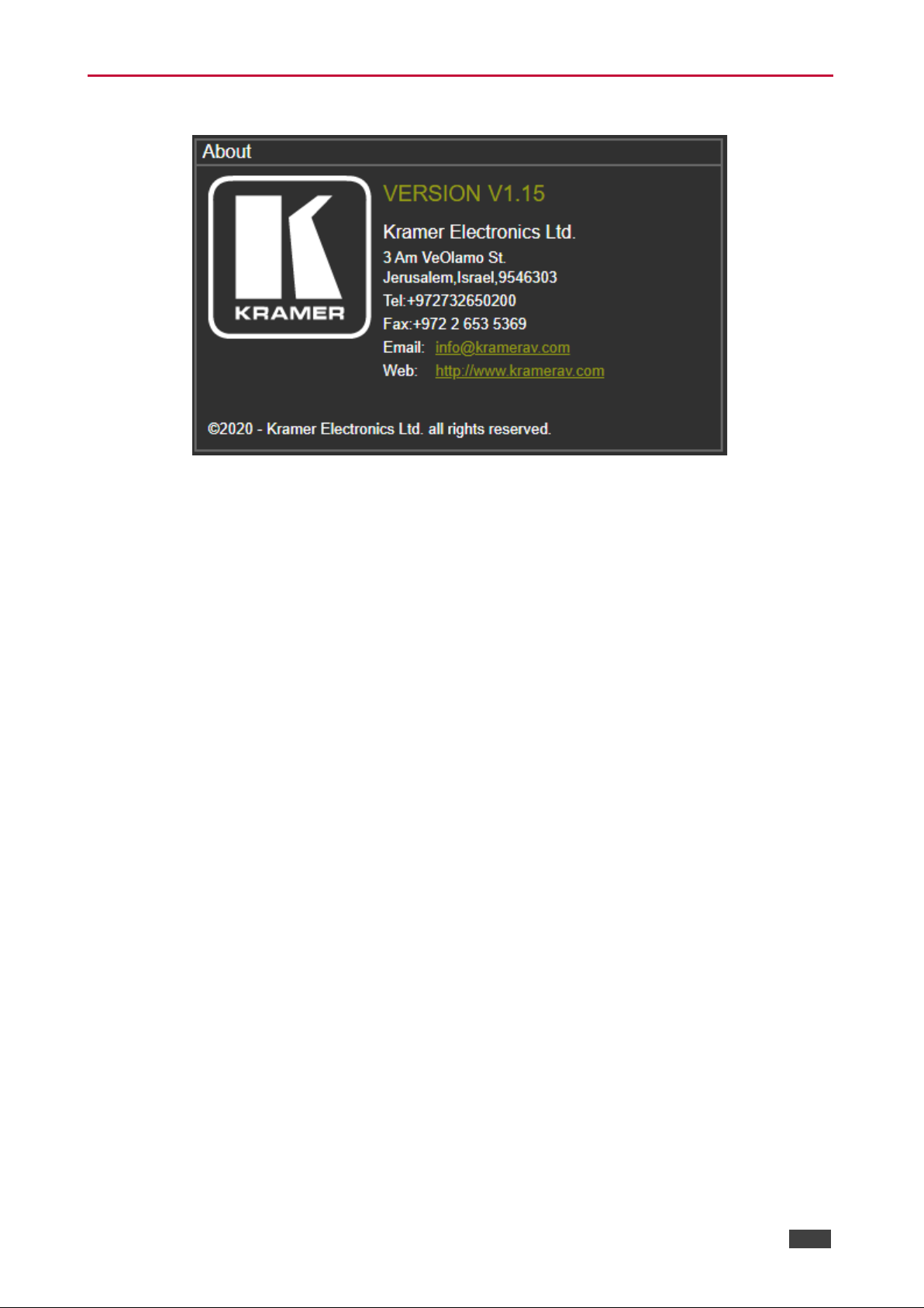
System Status in the Advanced page shows the device hardware status. If hardware failure
occurs or any of the parameters exceed their limits, system status indicates the problem.
To view system status:
1. In the Navigation pane, click Advanced. The Advanced page appears.
2. In System Status area, view power supply, temperature and fan indicators.
Figure 43: Advanced Page – System Status
Page 49
Kramer Electronics Ltd.
VP-551X – Using the Embedded Webpages
47
Viewing Device Information
Figure 44: About Page
Page 50

Kramer Electronics Ltd.
VP-551X – Upgrading the Firmware
48
Upgrading the Firmware
Upgrade the firmware via the webpages (see Updating the Firmware on page 28).
Page 51

Kramer Electronics Ltd.
VP-551X – Technical Specifications
49
Technical Specifications
Inputs
8 HDMI
On female HDMI connectors
1 Computer Graphics
On a 15-pin HD connector
1 Composite Video
On an RCA connector
8 Unbalanced Stereo Analog
Audio
On 3-pin terminal blocks (1 to accompany
each of the HDMI inputs)
1 Unbalanced Stereo Analog
Audio
On a 3-pin terminal block (to accompany the
Computer Graphics input)
1 Unbalanced Stereo Analog
Audio
On a 3-pin terminal block (to accompany the
CV input)
2 Microphone
On 6mm jacks
Outputs
1 HDBT
On an RJ-45 connector
1 HDMI
On a female HDMI connector
1 Balanced Analog Stereo Audio
On a 5-pin terminal block
1 Digital Audio
On a female RCA connector
1 Speaker
On a 4-pin terminal block
Ports
1 RS-232 (Data)
On a 3-pin terminal block
1 RS-232 (Control)
On a 3-pin terminal block
1 Ethernet
On an RJ-45 connector
Amplifier
Output Power
2 x 20W into 4Ω
Video
Max Bandwidth
18Gbps (6Gbps per graphic channel)
Max Resolution
4K@60Hz (4:4:4)
Compliance
HDMI and up to HDCP 2.2
Latency
Less than 2 frames
Extension Range
4k@30Hz
Up to 40m (130ft)
Full HD (1080p@60Hz)
Up to 70m (230ft)
Audio
Max. Input Level
1.3Vrms
Max. Output Level
2.35Vrms
THD + N
0.006%
Controls
Rear Panel
Mic type selection
Front Panel
IR remote, Input selection, freeze, mute,
XGA/1080p reset, and panel lock buttons,
OSD menu
Indication LEDs
Front Panel
IR LED
Selected input LEDs
1 Power on LED
Analog Audio
Speaker
2x20W into 4Ω
Power
Consumption
130VA
Source
100–240V AC 50/60Hz
Environmental
Conditions
Operating Temperature
0° to +40°C (32° to 104°F)
Storage Temperature
-40° to +70°C (-40° to 158°F)
Humidity
10% to 90%, RHL non-condensing
Regulatory
Compliance
Safety
CE, FCC
Environmental
RoHs, WEEE
Enclosure
Size
19” 1U
Type
Aluminum
Cooling
Fan ventilation
Page 52
Kramer Electronics Ltd.
VP-551X – Technical Specifications
50
General
Net Dimensions (W, D, H)
43.64cm x 23.72cm x 4.36cm
(17.18" x 9.34" x 1.72")
Shipping Dimensions (W, D, H)
55.00cm x 27.60cm x 10.70cm
(21.65" x 10.87" x 4.21")
Net Weight
2.3kg (5.1lbs) approx.
Shipping Weight
3.4kg (7.5lbs) approx.
Accessories
Included
Power adapter cord, IR remote control
Optional
To achieve specified extension distances,
use the recommended Kramer cables
available at www.kramerav.com/product/VP-
551X
Specifications are subject to change without notice at www.kramerav.com
Page 53
Kramer Electronics Ltd.
VP-551X – Technical Specifications
51
Default Communication Parameters
RS-232
Baud Rate:
115,200
Data Bits:
8
Stop Bits:
1
Parity:
None
Command Format:
ASCII
Example (Route the video HDMI2 input to the output ports):
#ROUTE 1,1,2<cr>
Ethernet
To reset the IP settings to the factory reset values go to: Menu->Setup -> Factory Reset-> press Enter to
confirm
IP Address:
192.168.1.39
Subnet mask:
255.255.0.0
Default gateway:
192.168.0.1
TCP Port #:
5000
UDP Port #:
50000
Default Username / Password:
Admin / Admin
Number of TCP clients
4
Number of UDP clients
2
Full Factory Reset
OSD
Go to: Menu-> Factory-> RESET-> YES and press Enter
Input Resolutions Support
VP-551X supports the following input resolutions.
HDMI Input Resolutions
480i/576i
480p/576p
1080i@60/50Hz
720p@60/50Hz
1080p@60/50Hz
1080p@24/25/30Hz
640x480@60/72/75/85Hz
800x600@56/60/72/75Hz
1024x768@60/70/75Hz
1280x1024@60/75Hz
1280x960@60Hz
1280x720@60Hz
1920x1080@60Hz
1600x1200@60Hz
1280x768@60Hz
1280x800@60Hz
1360x768@60Hz
1366x768@60Hz
1400x1050@60Hz
1600x900@60Hz RB
1680x1050@60Hz
1920x1200@60Hz RB
4K2K@50/60Hz (4:2:0),
4K2K@24/25/30/50/60Hz (4:4:4)
Computer Graphics Input Resolutions
640x480@60/72/75/85Hz
800x600@56/60/72/75Hz
1024x768@60/70/75Hz
1280x1024@60/75Hz
1280x960@60Hz
1280x720@60Hz
1920x1080@60Hz
1600x1200@60Hz
1280x768@60Hz
1280x800@60Hz
1360x768@60Hz
1366x768@60Hz
1400x1050@60Hz
1680x1050@60Hz
1920x1200@60Hz RB
CV Input Resolution
480i/576i
Page 54
Kramer Electronics Ltd.
VP-551X – Technical Specifications
52
Output Resolution Support
VP-551X supports the following output resolutions.
HDMI Output Resolutions
640x480@60Hz
800x600@60Hz
1024x768@60Hz
1280x768@60Hz
1360x768@60Hz
1280x720@60Hz
1280x800@60Hz
1280x1024@60Hz
1440x900@60Hz
1400x1050@60Hz
1680x1050@60Hz
1600x1200@60Hz
1920x1080@60Hz
1920x1200@60Hz RB
480p@60Hz
576p@50Hz
720p@50/60Hz
1080p@24/25/30/50/60Hz
2560x1440@60Hz RB
2560x1600@60Hz RB
4K/2K@50/60Hz (4:2:0)
4K/2K@24/25/30/50/60Hz (4:4:4)
HDBT Output Resolutions
640x480@60Hz
800x600@60Hz
1024x768@60Hz
1280x768@60Hz
1360x768@60Hz
1280x720@60Hz
1280x800@60Hz
1280x1024@60Hz
1440x900@60Hz
1400x1050@60Hz
1680x1050@60Hz
1600x1200@60Hz
1920x1080@60Hz
1920x1200@60Hz RB
480p@60Hz
576p@50Hz
720p@50/60Hz
1080p@24/25/30/50/60Hz
4K/2K@24/25/30/50/60Hz (4:4:4)
Default EDID
Monitor #1 [Real-time 0x0072]
Model name............... VP-551X
Manufacturer............. KMR
Plug and Play ID......... KMR060D
Serial number............ 49
Manufacture date......... 2018, ISO week 6
Filter driver............ None
-------------------------
EDID revision............ 1.3
Input signal type........ Digital
Color bit depth.......... Undefined
Display type............. Monochrome/grayscale
Screen size.............. 360 x 360 mm (20.0 in)
Power management......... Standby, Suspend
Extension blocs.......... 1 (CEA/CTA-EXT)
-------------------------
DDC/CI................... Not supported
Color characteristics
Default color space...... Non-sRGB
Display gamma............ 2.40
Red chromaticity......... Rx 0.611 - Ry 0.329
Green chromaticity....... Gx 0.313 - Gy 0.559
Blue chromaticity........ Bx 0.148 - By 0.131
White point (default).... Wx 0.320 - Wy 0.336
Additional descriptors... None
Timing characteristics
Horizontal scan range.... 15-136kHz
Vertical scan range...... 23-61Hz
Video bandwidth.......... 600MHz
CVT standard............. Not supported
GTF standard............. Not supported
Additional descriptors... None
Preferred timing......... Yes
Native/preferred timing.. 3840x2160p at 60Hz (16:9)
Modeline............... "3840x2160" 594.000 3840 4016 4104 4400 2160 2168 2178 2250 +hsync +vsync
Detailed timing #1....... 1920x1080p at 60Hz (16:9)
Modeline............... "1920x1080" 148.500 1920 2008 2052 2200 1080 1084 1089 1125 +hsync +vsync
Page 55

Kramer Electronics Ltd.
VP-551X – Technical Specifications
53
Standard timings supported
640 x 480p at 60Hz - IBM VGA
640 x 480p at 72Hz - VESA
640 x 480p at 75Hz - VESA
800 x 600p at 56Hz - VESA
800 x 600p at 60Hz - VESA
800 x 600p at 72Hz - VESA
800 x 600p at 75Hz - VESA
1024 x 768p at 60Hz - VESA
1024 x 768p at 70Hz - VESA
1024 x 768p at 75Hz - VESA
1280 x 1024p at 75Hz - VESA
1600 x 1200p at 60Hz - VESA STD
1280 x 1024p at 60Hz - VESA STD
1400 x 1050p at 60Hz - VESA STD
1920 x 1080p at 60Hz - VESA STD
640 x 480p at 85Hz - VESA STD
800 x 600p at 85Hz - VESA STD
1024 x 768p at 85Hz - VESA STD
1280 x 1024p at 85Hz - VESA STD
EIA/CEA/CTA-861 Information
Revision number.......... 3
IT underscan............. Supported
Basic audio.............. Supported
YCbCr 4:4:4.............. Supported
YCbCr 4:2:2.............. Supported
Native formats........... 0
Detailed timing #1....... 1440x900p at 60Hz (16:10)
Modeline............... "1440x900" 106.500 1440 1520 1672 1904 900 903 909 934 -hsync +vsync
Detailed timing #2....... 1366x768p at 60Hz (16:9)
Modeline............... "1366x768" 85.500 1366 1436 1579 1792 768 771 774 798 +hsync +vsync
Detailed timing #3....... 1920x1200p at 60Hz (16:10)
Modeline............... "1920x1200" 154.000 1920 1968 2000 2080 1200 1203 1209 1235 +hsync -vsync
CE video identifiers (VICs) - timing/formats supported
1920 x 1080p at 60Hz - HDTV (16:9, 1:1)
1920 x 1080p at 50Hz - HDTV (16:9, 1:1)
1280 x 720p at 60Hz - HDTV (16:9, 1:1)
1280 x 720p at 50Hz - HDTV (16:9, 1:1)
1920 x 1080i at 60Hz - HDTV (16:9, 1:1)
1920 x 1080i at 50Hz - HDTV (16:9, 1:1)
720 x 480p at 60Hz - EDTV (4:3, 8:9)
720 x 576p at 50Hz - EDTV (4:3, 16:15)
720 x 480i at 60Hz - Doublescan (4:3, 8:9)
720 x 576i at 50Hz - Doublescan (4:3, 16:15)
1920 x 1080p at 30Hz - HDTV (16:9, 1:1)
1920 x 1080p at 25Hz - HDTV (16:9, 1:1)
1920 x 1080p at 24Hz - HDTV (16:9, 1:1)
1920 x 1080p at 24Hz - HDTV (16:9, 1:1)
1920 x 1080p at 24Hz - HDTV (16:9, 1:1)
1920 x 1080p at 24Hz - HDTV (16:9, 1:1)
1920 x 1080p at 24Hz - HDTV (16:9, 1:1)
1920 x 1080p at 24Hz - HDTV (16:9, 1:1)
NB: NTSC refresh rate = (Hz*1000)/1001
CE audio data (formats supported)
LPCM 2-channel, 16/20/24 bit depths at 32/44/48 kHz
CE speaker allocation data
Channel configuration.... 2.0
Front left/right......... Yes
Front LFE................ No
Front center............. No
Rear left/right.......... No
Rear center.............. No
Front left/right center.. No
Rear left/right center... No
Rear LFE................. No
CE vendor specific data (VSDB)
IEEE registration number. 0x000C03
CEC physical address..... 1.0.0.0
Supports AI (ACP, ISRC).. No
Supports 48bpp........... Yes
Supports 36bpp........... Yes
Supports 30bpp........... Yes
Supports YCbCr 4:4:4..... Yes
Supports dual-link DVI... No
Maximum TMDS clock....... 300MHz
Audio/video latency (p).. n/a
Page 56

Kramer Electronics Ltd.
VP-551X – Technical Specifications
54
Audio/video latency (i).. n/a
HDMI video capabilities.. Yes
EDID screen size......... No additional info
3D formats supported..... Not supported
Data payload............. 030C001000783C20008001020304
CE vendor specific data (VSDB)
IEEE registration number. 0xC45DD8
CEC physical address..... 0.1.7.8
Supports AI (ACP, ISRC).. Yes
Supports 48bpp........... No
Supports 36bpp........... No
Supports 30bpp........... No
Supports YCbCr 4:4:4..... No
Supports dual-link DVI... No
Maximum TMDS clock....... 35MHz
YCbCr 4:2:0 capability map data
Data payload............. 0F000003
Report information
Date generated........... 9/24/2020
Software revision........ 2.91.0.1043
Data source.............. Real-time 0x0072
Operating system......... 10.0.18362.2
Raw data
00,FF,FF,FF,FF,FF,FF,00,2D,B2,0D,06,31,00,00,00,06,1C,01,03,80,24,24,8C,C2,90,20,9C,54,50,8F,26,
21,52,56,2F,CF,00,A9,40,81,80,90,40,D1,C0,31,59,45,59,61,59,81,99,08,E8,00,30,F2,70,5A,80,B0,58,
8A,00,BA,88,21,00,00,1E,02,3A,80,18,71,38,2D,40,58,2C,45,00,BA,88,21,00,00,1E,00,00,00,FC,00,56,
50,2D,35,35,31,58,0A,20,20,20,20,20,00,00,00,FD,00,17,3D,0F,88,3C,00,0A,20,20,20,20,20,20,01,F6,
02,03,3B,F0,52,10,1F,04,13,05,14,02,11,06,15,22,21,20,5D,5E,5F,60,61,23,09,07,07,83,01,00,00,6E,
03,0C,00,10,00,78,3C,20,00,80,01,02,03,04,67,D8,5D,C4,01,78,80,07,E4,0F,00,00,03,9A,29,A0,D0,51,
84,22,30,50,98,36,00,10,0A,00,00,00,1C,66,21,56,AA,51,00,1E,30,46,8F,33,00,10,09,00,00,00,1E,28,
3C,80,A0,70,B0,23,40,30,20,36,00,10,0A,00,00,00,1A,00,00,00,00,00,00,00,00,00,00,00,00,00,00,E0
---------------------------
Hardware data
BUS_SLOT = PCI00000.PCI00004.PCI00008.PCI0000C.PCI00010.PCI00014.PCI00018.PCI0001C
00000000 = 59108086.00900006.06000005.00000000.00000000.00000000.00000000.00000000
00000008 = 19018086.00100407.06040005.00810010.00000000.00000000.00010100.20004040
00000010 = 591B8086.00100407.03000004.00000010.F 2000 004 .0000 00 2F.C000000C.0000002F
000000A0 = A12F8086.02900406.0C033031.00800000.63380004.00000000.00000000.00000000
000000A2 = A1318086.00100006.11800031.00000000.F3018004.0000002F.00000000.00000000
000000A8 = A1608086.00100400.11800031.00800010.FFFFE004.0000002F.00000000.00000000
000000AA = A1628086.00100400.11800031.00800010.FFFFD004.0000002F.00000000.00000000
000000B0 = A13A8086.00100406.07800031.00800000.FFFFF004.0000002F.00000000.00000000
000000B8 = 282A8086.02B00407.01040031.00000000.63390000.6339C000.00005081.00005089
000000E0 = A1128086.00100406.060400F1.00810010.00000000.00000000.00020200.200000F0
000000E3 = A1138086.00100407.060400F1.00810010.00000000.00000000.00030300.20003030
000000E4 = A1148086.00100406.060400F1.00810010.00000000.00000000.00FE0400.200000F0
000000F8 = A1528086.02000007.06010031.00800000.00000000.00000000.00000000.00000000
000000FA = A1218086.00000006.05800031.00800000.63398000.00000000.00000000.00000000
000000FB = A1718086.00100006.04030031.00002010.F3010004.0000002F.00000000.00000000
000000FC = A1238086.02800003.0C050031.00000000.F3014004.0000002F.00000000.00000000
00000100 = 1C2010DE.00100006. 03 00 00A 1. 008 00 01 0.620 00 00 0.5 00 000 0C.00000000.6000000C
00000101 = 10F110DE.00100006.040300A1. 00 800000. 630FC 000 .000000 00. 0000 00 00. 00000000
00000200 = 24FD8086.00100406.02800078.00000010.63200004.00000000.00000000.00000000
00000300 = 816810EC.00100407.02000010.00000010.00003001.00000000.63104004.00000000
------- 02070000 = 00FFFFFF.FFFFFF00.2DB20D06.31000000.061C0103.8024248C.C290209C.54508F26
00000020 = 2152562F.CF00A940.81809040.D1C03159.45596159.819908E8.0030F270.5A80B058
00000040 = 8A00BA88.2100001E. 02 3A 801 8. 713 82D 40.582C4500.BA882100.001E0000.00FC0056
00000060 = 502D3535.31580A20.20202020.000000FD.00 17 3D0F. 883C000A. 20 202020.2 02001F6
02070100 = 02033BF0.52101F04.13051402.11061522.21205D5E.5F6 061 23.0 907 07 83. 01 00 00 6E
00000020 = 030C0010.00783C20.00800102. 030467D8.5DC40178.8007E40F.0000039A.29A0D051
00000040 = 84223050.98360010.0A000000.1C662156.AA51001E.30468F 33 .001009 00. 0000 1E2 8
00000060 = 3C80A070.B0234030.20360010.0A000000.1A000000.00000000.00000000.000000E0
Page 57
Kramer Electronics Ltd.
VP-551X – Protocol 3000
55
Protocol 3000
Kramer devices can be operated using Kramer Protocol 3000 commands sent via serial or
Ethernet ports.
Understanding Protocol 3000
Protocol 3000 commands are a sequence of ASCII letters, structured according to the
following.
• Command format:
Prefix
Command Name
Constant
(Space)
Parameter(s)
Suffix
#
Command
Parameter
<CR>
• Feedback format:
Prefix
Device ID
Constant
Command Name
Parameter(s)
Suffix
~
nn
@
Command
Parameter
<CR><LF>
• Command parameters – Multiple parameters must be separated by a comma (,). In
addition, multiple parameters can be grouped as a single parameter using brackets ([
and ]).
• Command chain separator character – Multiple commands can be chained in the
same string. Each command is delimited by a pipe character (|).
• Parameters attributes – Parameters may contain multiple attributes. Attributes are
indicated with pointy brackets (<…>) and must be separated by a period (.).
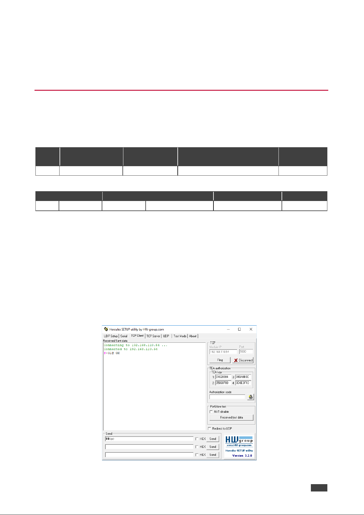
The command framing varies according to how you interface with the VS-88UT. The following
figure displays how the # command is framed using terminal communication software (such
as Hercules):
Page 58
Kramer Electronics Ltd.
VP-551X – Protocol 3000
56
Protocol 3000 Commands
Function
Description
Syntax
Parameters/Attributes
Example
#
Protocol handshaking.
Validates the Protocol
3000 connection and gets
the machine number.
Step-in master products
use this command to
identify the availability of
a device.
COMMAND
#<CR>
FEEDBACK
~nn@OK<CR><LF>
#<CR>
AUD-EMB
Set audio in video
embedding status.
COMMAND
#AUD-EMBin,out,status<CR>
FEEDBACK
~nn@AUD-EMB in,out,status<CR><LF>
in – Audio input to be embedded
number
0 = HDMI 1
1 = HDMI 2
2 = HDMI 3
3 = HDMI 4
4 = HDMI 5
5 = HDMI 6
6 = HDMI 7
7 = HDMI 8
out = 0
status – Embedding status
0 = Analog
1 = Embedded
2 = Auto
Set audio in video embedding
status for input 3 and the
output to analog:
#AUD-EMB 2,1,0< CR>
AUD-EMB?
Get audio in video
embedding status.
COMMAND
#AUD-EMB? in,out<CR>
FEEDBACK
~nn@AUD-EMB in,out,status<CR><LF>
in – Audio input to be embedded
number
0 = HDMI 1
1 = HDMI 2
2 = HDMI 3
3 = HDMI 4
4 = HDMI 5
5 = HDMI 6
6 = HDMI 7
7 = HDMI 8
out = 0
status – Embedding status
0 = Analog
1 = Embedded
2 = Auto
Get audio in video embedding
status for input 2 and the
output:
#AUD-EMB? 1,0<CR>
AUDIOBYPASS
Set audio bypass status.
COMMAND
#AUDIO-BYPASS status<CR>
FEEDBACK
#AUDIO-BYBASS status<CR>
status – On/Off
0 = Off
1 = On
Set audio-bypass to off:
#AUDIO-BYPASS0<CR>
AUDIOBYPASS?
Get audio bypass status.
COMMAND
#AUDIO-BYPASS? <CR>
FEEDBACK
#AUDIO-BYPASS? status<CR><LF>
status – On/Off
0 = Off
1 = On
Get audio bypass status:
#AUDIO-BYPASS?<CR>
AUD-LVL
Set volume level.
COMMAND
#AUD-LVLstage,channel,volume<CR>
FEEDBACK
~nn@AUD-LVL stage,channel,volume<CR><LF>
stage – Input/Output
0 = Input
1 = Output
2 – Line level
channel –
For Input:
0 = HDMI 1
1 = HDMI 2
2 = HDMI 3
3 = HDMI 4
4 = HDMI 5
5 = HDMI 6
6 = HDMI 7
7 = HDMI 8
8 = PC
9 = CV
For Output
0 = Line Output
1 = Speaker
volume – Volume level 0 to 100;
++ (increase current value by 1dB);
-- (decrease current value by 1dB)
Set AUDIO PC input level to
50:
#AUD-LVL 0,8,50<CR>
Page 59
Kramer Electronics Ltd.
VP-551X – Protocol 3000
57
Function
Description
Syntax
Parameters/Attributes
Example
AUD-LVL?
Get volume level.
COMMAND
#AUD-LVL? stage,channel<C R>
FEEDBACK
~nn@AUD-LVL stage,channel,volume<CR><LF>
stage – Input/Output
0 = Input
1 = Output
2 – Line level
channel –
For Input:
0 = HDMI 1
1 = HDMI 2
2 = HDMI 3
3 = HDMI 4
4 = HDMI 5
5 = HDMI 6
6 = HDMI 7
7 = HDMI 8
8 = PC
9 = CV
For Output
0 = Line Output
1 = Speaker
volume – Volume level 0 to 100;
Get Speaker audio level
#AUD-LVL? 1,1<CR>
BASS
Set audio bass level.
COMMAND
#BASSchannel,bass_level<CR>
FEEDBACK
~nn@BASSchannel,bass_level<CR><LF>
channel = 1
bass_level = 0-30
Set audio bass level 5:
#BASS1, 5<CR>
BASS?
Get audio bass level.
COMMAND
#BASS?channel<CR>
FEEDBACK
~nn@BASSchannel,bass_level<CR><LF>
channel = 1
bass_level = 0-30
Get audio bass level:
#BASS?1<CR>
BUILD-DATE?
Get device build date.
COMMAND
#BUILD-DATE? <CR>
FEEDBACK
~nn@BUILD-DATE date, time<CR><LF>
date – Format: YYYY/MM/DD where
YYYY = Year
MM = Month
DD = Day
time – Format: hh:mm:ss where
hh = hours
mm = minutes
ss = seconds
Get the device build date:
#BUILD-DATE?<CR>
CPEDID
Copy EDID data from the
output to the input
EEPROM.
Destination bitmap
size depends on device
properties (for 64 inputs it
is a 64-bit word).
Example: bitmap 0x0013
means inputs 1,2 and 5
are loaded with the new
EDID.
In certain products
Safe_mode is an optional
parameter. See the HELP
command for its
availability.
COMMAND
#CPEDIDedid_io,src_id,edid_io,dest_bitmap<CR>
or
#CPEDIDedid_io,src_id,edid_io,dest_bitmap,safe_mode<CR>
FEEDBACK
~nn@CPEDIDedid_io,src_id,edid_io,dest_bitmap<CR><LF>
~nn@CPEDIDedid_io,src_id,edid_io,dest_bitmap,safe_mode<CR
><LF>
edid_io – EDID source type (usually
output)
0 = Input
1 = Output
2 = Default EDID
3 = Custom EDID
src_id – Number of chosen source
stage
0 = Default EDID source
1 = Output 1
2 = Output 2
edid_io – EDID destination type
(usually input)
0 = Input
1 = Output
2 = Default EDID
3 = Custom EDID
dest_bitmap – Bitmap representing
destination IDs. Format: XXXX…X,
where X is hex digit. The binary form
of every hex digit represents
corresponding destinations.
0 = indicates that EDID data is not
copied to this destination.
1 = indicates that EDID data is
copied to this destination.
safe_mode – Safe mode
0 = device accepts the EDID as is
without trying to adjust
1 = device tries to adjust the EDID
(default value if no parameter is
sent)
Copy the EDID data from the
Output 1 (EDID source) to the
Input:
#CPEDID1,1,0,0 x1<CR>
Copy the EDID data from the
default EDID source to the
Input:
#CPEDID2,0,0,0 x1<CR>
DISPLAY?
Get output HPD status.
COMMAND
#DISPLAY?out_id<CR>
FEEDBACK
~nn@DISPLAYout_id,status<CR><LF>
out_id – Output number
1 = HDMI
2 = HDBT
status – HPD status according to
signal validation
0 = Signal or sink is not valid
1 = Signal or sink is valid
2 = Sink and EDID is valid
Get the output HPD status of
the HDMI output:
#DISPLAY?1<CR>
ETH-PORT
Set Ethernet port
protocol.
If the port number you
enter is already in use, an
error is returned.
The port number must be
within the following range:
0-(2^16-1).
COMMAND
#ETH-PORT portType,port_id<CR>
FEEDBACK
~nn@ETH-PORT portType,port_id<CR><LF>
portType – TCP/UDP
Port_id – TCP/UDP port number
TCP – (5000-5099)
UDP – (50000-50999)
Set TCP port number to 5000:
#ETH-PORT TCP,5000<CR>
ETH-PORT?
Get Ethernet port
protocol.
COMMAND
#ETH-PORT? port_type<CR>
FEEDBACK
~nn@ETH-PORT port_type,port_id<CR><LF>
port_type – TCP/UDP
port_id –
when port_type = TCP:
5000~5099
when port_type = UDP:
50000~50999
Get the Ethernet port number
for UDP:
#ETH-PORT? UDP<CR>
Page 60
Kramer Electronics Ltd.
VP-551X – Protocol 3000
58
Function
Description
Syntax
Parameters/Attributes
Example
FACTORY
Reset device to factory
default configuration.
This command
deletes all user data from
the device. The deletion
can take some time.
Your device may require
powering off and
powering on for the
changes to take effect.
COMMAND
#FACTORY<CR>
FEEDBACK
~nn@FACTORYOK<CR><LF>
Reset the device to factory
default configuration:
#FACTORY<CR>
FAN?
Get fan status.
COMMAND
#FAN? <CR>
FEEDBACK
~nn@FAN?status <CR><LF>
status –
0 = Fail
1 = Pass
Get fan status:
#FAN?<CR>
HDCP-MOD
Set HDCP mode.
Set HDCP working
mode on the device input:
HDCP supported HDCP_ON [default].
HDCP not supported HDCP OFF.
HDCP support changes
following detected sink MIRROR OUTPUT.
When you define 3 as the
mode, the HDCP status is
defined according to the
connected output in the
following priority: OUT 1,
OUT 2. If the connected
display on OUT 2
supports HDCP, but OUT
1 does not, then HDCP is
defined as not supported.
If OUT 1 is not
connected, then HDCP is
defined by OUT 2.
COMMAND
#HDCP-MOD stage,inp_id,mode<CR>
FEEDBACK
~nn@HDCP-MOD stage,inp_id,mode<CR><LF>
stage – Input/Output
0 = Input
1 = Output
inp_id – Input number:
1 = HDMI 1
2 = HDMI 2
3 = HDMI 3
4 = HDMI 4
5 = HDMI 5
6 = HDMI 6
7 = HDMI 7
8 = HDMI 8
Output number
1 = HDMI
2 = HDBT
mode – HDCP mode
Input:
0 = Off
1 = On
Output:
2 = Follow input
3 = Follow output
Set the input HDCP-MODE of
input HDMI 1 to Off:
#HDCP-MOD 0,1,0<CR>
HDCP-MOD?
Get HDCP mode.
Set HDCP working
mode on the device input:
HDCP supported HDCP_ON [default].
HDCP not supported HDCP OFF.
HDCP support changes
following detected sink MIRROR OUTPUT.
COMMAND
#HDCP-MOD? stage,inp_id<CR>
FEEDBACK
~nn@HDCP-MOD stage,inp_id,mode<CR><LF>
stage – Input/Output
0 = Input
1 = Output
inp_id – Input number:
1 = HDMI 1
2 = HDMI 2
3 = HDMI 3
4 = HDMI 4
5 = HDMI 5
6 = HDMI 6
7 = HDMI 7
8 = HDMI 8
Output number
1 = HDMI
2 = HDBT
mode – HDCP mode
Input:
0 = Off
1 = On
Output:
2 = Follow input
3 = Follow output
Get the input HDCP-MODE of
input HDMI 1:
#HDCP-MOD? 0,1<CR>
HELP
Get command list or help
for specific command.
COMMAND
#HELP<CR>
#HELPcommand_name<CR>
FEEDBACK
1. Multi-line:
~nn@Devicecommand,command…<CR><LF>
To get help for command use: HELP (COMMAND_NAME)<CR><LF>
~nn@HELPco mmand:<CR><LF>
description<CR><LF>
USAGE:usage<CR><LF>
command – Name of a specific
command
Get the command list:
#HELP<CR>
To get help for
AV-SW-TIMEOUT:
HELPAV-SW-TIMEOUT<CR>
IMAGE-PROP
Set the image size.
Sets the image
properties of the selected
scaler.
COMMAND
#IMAGE-PROP scaler,status<CR>
FEEDBACK
~nn@IMAGE-PROP P1,P2…<CR><LF>
scaler = 1
status – Status
0 = Over scan
1 = Full
2 = Best fit
3 = Pan scan
4 = Letter box
5 = Under 2
6 = Under 1
7 = Follow in
Set the image size to Full:
#IMAGE-PROP 1,1<CR>
Page 61
Kramer Electronics Ltd.
VP-551X – Protocol 3000
59
Function
Description
Syntax
Parameters/Attributes
Example
IMAGE-PROP?
Get the image size.
Gets the image
properties of the selected
scaler.
COMMAND
#IMAGE-PROP? P1,…,P6<CR>
FEEDBACK
~nn@IMAGE-PROP P1,P2…<CR><LF>
scaler = 1
status – Status
0 = Over scan
1 = Full
2 = Best fit
3 = Pan scan
4 = Letter box
5 = Under 2
6 = Under 1
7 = Follow in
Get the image size:
#IMAGE-PROP? 1<CR>
LOCK-FP
Lock the front panel.
COMMAND
#LOCK-FPL ock/U nlock<CR>
FEEDBACK
~nn@LOCK-FP Lock/Unlock<CR><LF>
Lock/Unlock – On/Off
0 = Off unlocks front panel
1 = On locks front panel
Unlock front panel:
#LOCK-FP 0<CR>
LOCK-FP?
Get the front panel lock
state.
COMMAND
#LOCK-FP? <CR>
FEEDBACK
~nn@LOCK-FP Lock/Unlock<CR><LF>
Lock/Unlock – On/Off
0 = Off unlocks front panel
1 = On locks front panel
Get the front panel lock state:
#LOCK-FP?<CR>
LOUDNESS
Set audio loudness.
COMMAND
#LOUDNESSchannel,loudness<CR>
FEEDBACK
~nn@LOUDNESSchannel,loudness<CR><LF>
channel = 1
loudness – On/Off
0 = Off
1 = On
Set audio loudness:
#LOUDNESS1,1<CR>
LOUDNESS?
Get audio loudness.
COMMAND
#LOUDNESS?channel<CR>
FEEDBACK
~nn@LOUDNESSchannel,loudness<CR><LF>
channel = 1
loudness – On/Off
0 = Off
1 = On
Get audio loudness:
#LOUDNESS?1<CR>
MIC-GAIN
Set the microphone gain.
Sets the microphone
input audio gain.
COMMAND
#MIC-GAIN P1,P2,P3<CR>
FEEDBACK
~nn@MIC-GAIN P1,P2,P3<CR><LF>
P1 = 0
P1 – Mic number
0 = Mic 1
1 = Mic 2
P3 – Level = 0 to 100
++ increase current value
– decrease current value
Set mic 1 gain to 35:
#MIC-GAIN 0,0,35<CR>
MIC-GAIN?
Get the microphone gain.
Gets the microphone
input audio gain.
COMMAND
#MIC-GAIN? P1,P2<CR>
FEEDBACK
~nn@MIC-GAIN P1,P2,P3<CR><LF>
P1 = 0
P1 – Mic number
0 = Mic 1
1 = Mic 2
P3 – Level = 0 to 100
Get the mic 2 gain:
#MIC-GAIN? 0,1<CR>
MIC-TLK
Set mic talkover
parameters.
COMMAND
#MIC-TLKchannel,P1,value<CR>
FEEDBACK
~nn@MIC-TLK channel,P1 ,va lue<CR><LF>
channel = 0
P1 – Parameter setting
0 = Depth
1 = Trigger
2 = Attack time
3 = Hold time
4 = Release time
value – P1 value (in corresponding
to P1 units)
Depth: 0-100%
Trigger: 0-100 (-60dB to 40dB)
Attack time/Hold time/Release time:
0-200 (0 to 20sec)
Set mic depth to 50:
#MIC-TLK 0,0,50<CR>
MIC-TLK?
Get mic talkover
parameters.
COMMAND
#MIC-TLK? channel,P1<CR>
FEEDBACK
~nn@MIC-TLK channel,P1 ,va lue<CR><LF>
channel = 0
P1 – Parameter setting
0 = Depth
1 = Trigger
2 = Attack time
3 = Hold time
4 = Release time
value – P1 value (in corresponding
to P1 units)
Depth: 0-100%
Trigger: 0-100 (-60dB to 40dB)
Attack time/Hold time/Release time:
0-200 (0 to 20sec)
Get mic trigger value:
#MIC-TLK? 0,1<CR>
MODEL?
Get device model.
This command
identifies equipment
connected to VP-551X
and notifies of identity
changes to the connected
equipment. The Scaler
saves this data in
memory to answer
REMOTE-INFO requests.
COMMAND
#MODEL?<CR>
FEEDBACK
~nn@MODELmodel_name<CR><LF>
model_name – String of up to 19
printable ASCII chars
Get the device model:
#MODEL?<CR>
MUTE
Set audio mute.
COMMAND
#MUTEchannel,mute_mode<CR>
FEEDBACK
~nn@MUTEchannel,mute_mode<CR><LF>
channel –
0 = Output
1 – Scaler
mute_mode – On/Off
0 = Off
1 = On
Set output to mute:
#MUTE0, 1<CR>
MUTE?
Get audio mute.
COMMAND
#MUTE?channel<CR>
FEEDBACK
~nn@MUTEchannel,mute_mode<CR><LF>
channel –
0 = Output
1 – Scaler
mute_mode – On/Off
0 = Off
1 = On
Get mute status of output
#MUTE0?<CR>
Page 62
Kramer Electronics Ltd.
VP-551X – Protocol 3000
60
Function
Description
Syntax
Parameters/Attributes
Example
NAME
Set machine (DNS)
name.
The machine name is
not the same as the
model name. The
machine name is used to
identify a specific
machine or a network in
use (with DNS feature
on).
COMMAND
#NAMEmachine_name<CR>
FEEDBACK
~nn@NAMEma chine_name<CR><LF>
machine_name – String of up to 15
alpha-numeric chars (can include
hyphen, not at the beginning or end)
Set the DNS name of the
device to room-442:
#NAMEroom-442<CR>
NAME?
Get machine (DNS)
name.
The machine name is
not the same as the
model name. The
machine name is used to
identify a specific
machine or a network in
use (with DNS feature
on).
COMMAND
#NAME?<CR>
FEEDBACK
~nn@NAMEma chine_name<CR><LF>
machine_name – String of up to 15
alpha-numeric chars (can include
hyphen, not at the beginning or end)
Get the DNS name of the
device:
#NAME?<CR>
NAME-RST
Reset machine (DNS)
name to factory default.
Factory default of
machine (DNS) name is
“KRAMER_” + 4 last
digits of device serial
number.
COMMAND
#NAME-RST<CR>
FEEDBACK
~nn@NAME-RST OK<CR><LF>
Reset the machine name (S/N
last digits are 0102):
#NAMERSTKRAMER_0102<CR>
NET-DHCP
Set DHCP mode.
COMMAND
#NET-DHCP dhcp_state<CR>
FEEDBACK
~nn@NET-DHCP dhcp_state<CR><LF>
dhcp_state –
0 = Off
1 = On (Use DHCP if unavailable,
use the IP address set by the
factory or the net-ip
command).
Enable DHCP mode:
#NET-DHCP 1<CR>
NET-DHCP?
Get DHCP mode.
COMMAND
#NET-DHCP?<CR>
FEEDBACK
~nn@NET-DHCP dhcp_state <CR><LF>
dhcp_state –
0 = Off
1 = On (Use DHCP if unavailable,
use the IP address set by the
factory or the net-ip
command).
Get DHCP mode:
#NET-DHCP? <CR>
NET-GATE
Set gateway IP.
A network gateway
connects the device via
another network and
maybe over the Internet.
Be careful of security
issues. For proper
settings consult your
network administrator.
COMMAND
#NET-GATE ip_address<CR>
FEEDBACK
~nn@NET-GATE ip_address<CR><LF>
ip_address – Format:
xxx.xxx.xxx.xxx
Set the gateway IP address to
192.168.0.1:
#NETGATE192.168.000.001<CR
>
NET-GATE?
Get gateway IP.
A network gateway
connects the device via
another network and
maybe over the Internet.
Be aware of security
problems.
COMMAND
#NET-GATE? <CR>
FEEDBACK
~nn@NET-GATE ip_address<CR><LF>
ip_address – Format:
xxx.xxx.xxx.xxx
Get the gateway IP address:
#NET-GATE? <CR>
NET-IP
Set IP address.
For proper settings
consult your network
administrator.
COMMAND
#NET-IPip_address<CR>
FEEDBACK
~nn@NET-IP ip_address<CR><LF>
ip_address – Format:
xxx.xxx.xxx.xxx
Set the IP address to
192.168.1.39:
#NETIP192.168.001.039<CR>
NET-IP?
Get IP address.
COMMAND
#NET-IP?<CR>
FEEDBACK
~nn@NET-IP ip_address<CR><LF>
ip_address – Format:
xxx.xxx.xxx.xxx
Get the IP address:
#NET-IP? <CR>
NET-MAC?
Get MAC address.
For backward
compatibility, the id
parameter can be
omitted. In this case, the
Network ID, by default, is
0, which is the Ethernet
control port.
COMMAND
#NET-MAC? id<CR>
FEEDBACK
~nn@NET-MAC id,mac_address<CR><LF>
id – Network ID–the device network
interface (if there are more than one).
Counting is 0 based, meaning the
control port i s ‘0’, additional ports are
1,2,3….
mac_address – Unique MAC
address. Format: XX-XX-XX-XX-XXXX where X is hex digit
#NET-MAC? id<CR>
NET-MASK
Set subnet mask.
For proper settings
consult your network
administrator.
COMMAND
#NET-MASK net_mask<CR>
FEEDBACK
~nn@NET-MASK net_mask<CR><LF>
net_mask – Format: xxx.xxx.xxx.xxx
Set the subnet mask to
255.255.0.0:
#NETMASK255.255.000.000<CR
>
NET-MASK?
Get subnet mask.
COMMAND
#NET-MASK? <CR>
FEEDBACK
~nn@NET-MASK net_mask<CR><LF>
net_mask – Format: xxx.xxx.xxx.xxx
Get the subnet mask:
#NET-MASK?<CR>
PROT-VER?
Get device protocol
version.
COMMAND
#PROT-VER? <CR>
FEEDBACK
~nn@PROT-VER 3000:version<CR><LF>
version – XX.XX where X is a
decimal digit
Get the device protocol
version:
#PROT-VER? <CR>
PSU?
Get PSU status.
COMMAND
#PSU? <CR>
FEEDBACK
~nn@PSU?status <CR><LF>
status –
0 = Fail
1 = Pass
Get PSU status:
#PSU? <CR>
Page 63
Kramer Electronics Ltd.
VP-551X – Protocol 3000
61
Function
Description
Syntax
Parameters/Attributes
Example
RESET
Reset device.
To avoid locking the
port due to a USB bug in
Windows, disconnect
USB connections
immediately after running
this command. If the port
was locked, disconnect
and reconnect the cable
to reopen the port.
COMMAND
#RESET<CR>
FEEDBACK
~nn@RESETOK<CR><LF>
Reset the device:
#RESET<CR>
ROUTE
Set layer routing.
This command
replaces all other routing
commands.
COMMAND
#ROUTElayer,dest,src<CR>
FEEDBACK
~nn@ROUTElayer,dest,src<CR><LF>
layer Layer Enumeration
1 = Video+audio
dest
1 = Scaler
src – Source id
1 = HDMI 1
2 = HDMI 2
3 = HDMI 3
4 = HDMI 4
5 = HDMI 5
6 = HDMI 6
7 = HDMI 7
8 = HDMI 8
9 = PC
10 = CV
Route HDMI 2 to the output:
#ROUTE1,1,2<CR>
ROUTE?
Get layer routing.
This command
replaces all other routing
commands.
COMMAND
#ROUTE?layer,dest<CR>
FEEDBACK
~nn@ROUTElayer,dest,src<CR><LF>
layer Layer Enumeration
1 = Video+audio
dest
1 = Scaler
src – Source id
1 = HDMI 1
2 = HDMI 2
3 = HDMI 3
4 = HDMI 4
5 = HDMI 5
6 = HDMI 6
7 = HDMI 7
8 = HDMI 8
9 = PC
10 = CV
Get the layer routing:
#ROUTE? layer,dest
<CR>
SCLR-AS
Set auto-sync features.
Sets the auto sync
features for the selected
scaler.
COMMAND
#SCLR-ASP1,P2<CR>
FEEDBACK
Set / Get :
~nn@SCLR-AS P1,P2….<CR><LF>
P1 –1
P2 – Sync Speed
0 = disable
1 = fast
2 = slow
3 = immediate
Set auto-sync to fast:
#SCLR-AS 1,1<CR>
SCLR-AS?
Get auto-sync features.
Gets the auto sync
features for the selected
scaler.
COMMAND
#SCLR-AS? P1<CR>
FEEDBACK
Set / Get :
~nn@SCLR-AS P1,P2….<CR><LF>
P1 –1
P2 – Sync Speed
0 = disable
1 = fast
2 = slow
3 = immediate
Get auto-sync features:
#SCLR-AS? 1<CR>
SCLR-AUDIODELAY
Set the scaler audio
delay.
Sets the audio delay
for the selected audio
output.
COMMAND
#SCLR-AUDIO-DELAYP1,P2<CR>
FEEDBACK
~nn@SCLR-AUDIO-DELAYP1,P2<CR><LF>
P1 – Audio output number
1 = Scaler
P2 – Delay
0 = Off
1 = 40ms
2 = 110ms
3 = 150ms
Set the scaler audio delay to
40ms:
#SCLR-AUDIO-DELAY1,1<C
R>
SCLR-AUDIODELAY?
Get the scaler audio
delay.
Gets the audio delay
for the selected audio
output.
COMMAND
#SCLR-AUDIO-DELAY?P1<CR>
FEEDBACK
~nn@SCLR-AUDIO-DELAYP1,P2<CR><LF>
P1 – Audio output number
1 = Scaler
P2 – Delay
0 = Off
1 = 40ms
2 = 110ms
3 = 150ms
Get the scaler audio delay:
#SCLR-AUDIO-DELAY?1<CR
>
SCLR-PCAUTO
Set PC auto sync of
scaler.
Trigger the Auto
Adjust feature of PC
input.
COMMAND
#SCLR-PCAUTO P1,P2<CR>
FEEDBACK
~nn@SCLR-PCAUTOP1,P2….<CR><LF>
P1 – Scaler Number
1 = Scaler1
P2 –Yes (“ Yes” trig gers the Auto-scan
function. When complete, the unit
returns to the “ No” state)
Set PC auto sync of scaler:
#SCLR-PCAUTO 1,yes<CR>
SIGNAL?
Get input signal status.
COMMAND
#SIGNAL?inp_id<CR>
FEEDBACK
~nn@SIGNALinp_id,status<CR><LF>
inp_id – Input number
1 = HDMI 1
2 = HDMI 2
3 = HDMI 3
4 = HDMI 4
5 = HDMI 5
6 = HDMI 6
7 = HDMI 7
8 = HDMI 8
status – Signal status according to
signal validation:
0 = Off
1 = On
Get the input signal lock status
of IN 1:
#SIGNAL?1<CR>
SN?
Get device serial
number.
COMMAND
#SN?<CR>
FEEDBACK
~nn@SNserial_number<CR><LF>
serial_number – 14 decimal digits,
factory assigned
Get the device serial number:
#SN?<CR>
Page 64
Kramer Electronics Ltd.
VP-551X – Protocol 3000
62
Function
Description
Syntax
Parameters/Attributes
Example
STANDBY
Set standby mode.
COMMAND
#STANDBYon_off<CR>
FEEDBACK
~nn@STANDBYvalue<CR><LF>
value – On/Off
0 = Off
1 = On
Set standby mode:
#STANDBY1<CR>
STANDBY?
Get standby mode status.
COMMAND
#STANDBY?<CR>
FEEDBACK
~nn@STANDBYvalue<CR><LF>
value – On/Off
0 = Off
1 = On
Get standby mode status:
#STANDBY?<CR>
TEMPERATURE
?
Get temperature status.
COMMAND
#TEMPERATURE? <CR>
FEEDBACK
~nn@TEMPERATURE?status<CR><LF>
status –
0 = Fail
1 = Pass
Get temperature status:
#TEMP ERATU RE?<CR>
TEST-MODE
Perform device test
according tow defined
test parameters.
This command starts
device test procedure.
COMMAND
#TEST-MODE<CR>
FEEDBACK
~nn@TEST-MODE result<CR><LF>
result – Test Results
0 = OK
1 = Failed (general)
2…..N – Device specific failed error
code
Perform device test according
to defined test parameters:
#TEST-MODE<CR>
TLK
Set audio talkover mode
status.
COMMAND
#TLKchannel,talkover_mode<CR>
FEEDBACK
~nn@TLKchannel,talkover_mode<CR><LF>
channel = 1 (scaler)
talkover_mode –
0 = off
1 = mixer
2 = talkover
3 = mic only
Set audio talkover mode
status:
#TLK1, 1<CR>
TLK?
Get audio talkover mode
status.
COMMAND
#TLK?channel<CR>
FEEDBACK
~nn@TLKchannel,talkover_mode<CR><LF>
channel = 1 (scaler)
talkover_mode –
0 = off
1 = mixer
2 = talkover
3 = mic only
Get audio talkover mode
status:
#TLK?1<CR>
TREBLE
Set audio treble level.
COMMAND
#TREBLEchannel,treble_level<CR>
FEEDBACK
~nn@TREBLEchannel,treble_level<CR><LF>
channel = 1 (scaler)
treble_level – Audio parameter in
Kramer units 0-30
Set audio treble level to 1:
#TREBLE1,1<CR>
TREBLE?
Get audio treble level.
COMMAND
#TREBLE?channel<CR>
FEEDBACK
~nn@TREBLEchannel,treble_level<CR><LF>
channel = 1 (scaler)
treble_level – Audio parameter in
Kramer units 0-30
Get audio treble level:
#TREBLE?1<CR>
VERSION?
Get firmware version
number.
COMMAND
#VERSION?<CR>
FEEDBACK
~nn@VERSIONfirmware_version<CR><LF>
firmware_version – XX.XX.XXXX
where the digit groups are:
major.minor.build version
Get the device firmware
version number:
#VERSION?<CR>
VFRZ
Set freeze on selected
output.
COMMAND
#VFRZout_id,freeze_flag<CR>
FEEDBACK
~nn@VFRZwin_num,freeze_flag<CR><LF>
out_id – 1 (scaler)
freeze_flag – On/Off
0 = Off
1 = On
Set freeze on selected output:
#VFRZ1, 1<CR>
VFRZ?
Get output freeze status.
COMMAND
#VFRZ?out_id<CR>
FEEDBACK
~nn@VFRZwin_num,freeze_flag<CR><LF>
out_id – 1 (scaler)
freeze_flag – On/Off
0 = Off
1 = On
Get output freeze status:
#VFRZ?1<CR>
VIDEOBYPASS
Set video bypass status.
COMMAND
#VIDEO -BYPASSstatus<CR>
FEEDBACK
#VIDEO -BYBASSstatus<CR>
status – On/Off
0 = Off
1 = On
Set audio-bypass to off:
#VIDEO -BYPASS0<CR>
VIDEO BYPASS?
Get video bypass status.
COMMAND
#VIDEO -BYPASS?<CR>
FEEDBACK
#VIDEO -BYPASS?status<CR><LF>
status – On/Off
0 = Off
1 = On
Get audio bypass status:
# VIDEO -BYPASS?<CR>
Page 65
Kramer Electronics Ltd.
VP-551X – Protocol 3000
63
Function
Description
Syntax
Parameters/Attributes
Example
VID-RES
Set output resolution.
“Set” command is only
applicable for
stage=Output.
“Set” command with
is_native=ON sets native
resolution on selected
output (resolution index
sent = 0). Device sends
as answer actual VIC ID
of native resolution.
“Get” command with
is_native=ON returns
native resolution VIC,
with is_native=OFF
returns current resolution.
To use “custom
resolutions” (entr ies 100-
105 In View Modes),
define them using the
DEF-RES command.
COMMAND
#VID-RESstage,stage_id,is_native,resolution<CR>
FEEDBACK
~nn@VID-RES stage,stage_id,is_native,resolution<CR><LF>
stage – Output
1 = Output
stage_id = 1 (scaler )
is_native – Native resolution flag
0 = Off
resolution – Resolution index
200= Native HDMI
201=640x480
202=800x600
203=1024x768
204=1280x768
205=1360x768
206=1280x720
207=1280x800
208=1280x1024
209=1440x900
210=1400x1050
211=1680x1050
212=1600x1200
213=1920x1080
214=1920x1200
215=2560x1600
216=2560x1440
217=480p
218=576p
219=720p50
220=720p60
221=1080p24
222=1080p25
223=1080p30
224=1080p50
225=1080p60
226=4K24
227=4K25
228=4K30
229=4K50
230=4K60
231=4K50(4:2:0)
232=4K60(4:2:0)
233=Native HDBT
Set output resolution to 480p:
#VID-RES 1,1,0, 217<CR>
VID-RES?
Set output resolution.
“Get” command is
only applicable for
stage=Output.
“Set” command with
is_native=ON sets native
resolution on selected
output (resolution index
sent = 0). Device sends
as answer actual VIC ID
of native resolution.
“Get” command with
is_native=ON returns
native resolution VIC,
with is_native=OFF
returns current resolution.
To use “custom
resolutions” (entr ies 100-
105 In View Modes),
define them using the
DEF-RES command.
COMMAND
#VID-RES? stage,stage_id, is_native<CR>
FEEDBACK
~nn@VID-RES? stage,stage_id,is_native,resolution<CR><LF>
stage –Output
1 = Output
stage_id = 1 (scaler )
is_native – Native resolution flag
0 = Off
resolution – Resolution index
200= Native HDMI
201=640x480
202=800x600
203=1024x768
204=1280x768
205=1360x768
206=1280x720
207=1280x800
208=1280x1024
209=1440x900
210=1400x1050
211=1680x1050
212=1600x1200
213=1920x1080
214=1920x1200
215=2560x1600
216=2560x1440
217=480p
218=576p
219=720p50
220=720p60
221=1080p24
222=1080p25
223=1080p30
224=1080p50
225=1080p60
226=4K24
227=4K25
228=4K30
229=4K50
230=4K60
231=4K50(4:2:0)
232=4K60(4:2:0)
233=Native HDBT
Get output resolution:
#VID-RES? 1,1,0<CR>
VMUTE
Set enable/disable video
on output.
COMMAND
#VMUTEoutput_id,flag<CR>
FEEDBACK
~nn@VMUTEoutput_id,flag<CR><LF>
output_id = 1 (scaler)
flag – Video Mute
0– Off (video enabled)
1– On (video disabled)
Disable the video output on
OUT 1:
#VMUTE1,0<CR>
VMUTE?
Get video on output
status.
COMMAND
#VMUTE?output_id_<CR>
FEEDBACK
~nn@VMUTEoutput_id,flag<CR><LF>
output_id = 1 (scaler)
flag – Video Mute
0– Off (video enabled)
1– On (video disabled)
Get video on output status:
#VMUTE?1<CR>
Page 66

Kramer Electronics Ltd.
VP-551X – Protocol 3000
64
Result and Error Codes
Syntax
In case of an error, the device responds with an error message. The error message syntax:
• ~NN@ERR XXX<CR><LF> – when general error, no specific command
• ~NN@CMD ERR XXX<CR><LF> – for specific command
• NN – machine number of device, default = 01
• XXX – error code
Error Codes
Error Name
Error Code
Description
P3K_NO_ERROR
0
No error
ERR_PROTOCOL_SYNTAX
1
Protocol syntax
ERR_COMMAND_NOT_AVAILABLE
2
Command not available
ERR_PARAMETER_OUT_OF_RANGE
3
Parameter out of range
ERR_UNAUTHORIZED_ACCESS
4
Unauthorized access
ERR_INTERNAL_FW_ERROR
5
Internal FW error
ERR_BUSY
6
Protocol busy
ERR_WRONG_CRC
7
Wrong CRC
ERR_TIMEDOUT
8
Timeout
ERR_RESERVED
9
(Reserved)
ERR_FW_NOT_ENOUGH_SPACE
10
Not enough space for data (firmware, FPGA…)
ERR_FS_NOT_ENOUGH_SPACE
11
Not enough space – file system
ERR_FS_FILE_NOT_EXISTS
12
File does not exist
ERR_FS_FILE_CANT_CREATED
13
File can’t be created
ERR_FS_FILE_CANT_OPEN
14
File can’t open
ERR_FEATURE_NOT_SUPPORTED
15
Feature is not supported
ERR_RESERVED_2
16
(Reserved)
ERR_RESERVED_3
17
(Reserved)
ERR_RESERVED_4
18
(Reserved)
ERR_RESERVED_5
19
(Reserved)
ERR_RESERVED_6
20
(Reserved)
ERR_PACKET_CRC
21
Packet CRC error
ERR_PACKET_MISSED
22
Packet number isn't expected (missing packet)
ERR_PACKET_SIZE
23
Packet size is wrong
ERR_RESERVED_7
24
(Reserved)
ERR_RESERVED_8
25
(Reserved)
ERR_RESERVED_9
26
(Reserved)
ERR_RESERVED_10
27
(Reserved)
ERR_RESERVED_11
28
(Reserved)
ERR_RESERVED_12
29
(Reserved)
ERR_EDID_CORRUPTED
30
EDID corrupted
ERR_NON_LISTED
31
Device specific errors
ERR_SAME_CRC
32
File has the same CRC – no changed
ERR_WRONG_MODE
33
Wrong operation mode
ERR_NOT_CONFIGURED
34
Device/chip was not initialized
Page 67

The warranty obligations of Kramer Electronics Inc. (“Kramer Elect ronics ”) f or this product are limited to the term s set fort h below:
What is Covered
This limited warranty covers defects in materials and workmanship in this product.
What is Not Covered
This limited warranty does not cover any damage, deterioration or malfunction resulting from any alteration, modification, improper or unreasonable use or
maintenance, misuse, abuse, accident, neglect, exposure to excess moisture, fire, improper packing and shipping (such claims must be presented to the carrier),
lightning, power surges, or other acts of nature. This limited warranty does not cover any damage, deterioration or malfunction resulting from the installation or
removal of this product from any installation, any unauthorized tampering with this product, any repairs attempted by anyone unauthorized by Kramer Electronics
to make such repairs, or any other cause which does not relate directly to a defect in materials and/or workmanship of this product. This limited warranty does not
cover cartons, equipment enclosures, cables or accessories used in conjunction with this product.
Without limiting any other exclusion herein, Kramer Electronics does not warrant that the product covered hereby, including, without limitation, the technology
and/or integrated circuit(s) included in the product, will not become obsolete or that such items are or will remain compatible with any other product or technology
with which the product may be used.
How Long this Coverage Lasts
The standard limited warranty for Kramer products is seven (7) years from the date of original purchase, with the following exceptions:
1. All Kramer VIA hardware products are covered by a standard three (3) year warranty for the VIA hardware and a standard three (3) year
warranty for firmware and software updates; all Kramer VIA accessories, adapters, tags, and dongles are covered by a standard one (1) year
warranty.
2. Kramer fiber optic cables, adapter-size fiber optic extenders, pluggable optical modules, active cables, cable retractors, ring mounted
adapters, portable power chargers, Kramer speakers, and Kramer touch panels are all covered by a standard one (1) year warranty.
3. All Kramer Cobra products, all Kramer Calibre products, all Kramer Minicom digital signage products, all HighSecLabs products, all
streaming, and all wireless products are covered by a standard three (3) year warranty.
4. All Sierra Video MultiViewers are covered by a standard five (5) year warranty.
5. Sierra switchers & control panels are covered by a standard seven (7) year warranty (excluding power supplies and fans that are covered for
three (3) years).
6. K-Touch software is covered by a standard one (1) year warranty for software updates.
7. All Kramer passive cables are covered by a ten (10) year warranty.
Who is Covered
Only the original purchaser of this product is covered under this limited warranty. This limited warranty is not transferable to subsequent purchas ers or owners of
this product.
What Kramer Electronics Will Do
Kramer Electronics will, at its sole option, provide one of the following three remedies to whatever extent it shall deem necessary to satisfy a proper claim under
this limited warranty:
1. Elect to repair or facilitate the repair of any defective parts within a reasonable period of time, free of any charge for the necessary parts and
labor to complete the repair and restore this product to its proper operating condition. Kramer Electronics will also pay the shipping costs
necessary to return this product once the repair is complete.
2. Replace this product with a direct replacement or with a similar product deemed by Kramer Electronics to perform substantially the same
function as the original product. If a direct or similar replace ment product is supp lied, the original product’s e nd warranty date remains
unchanged and is transferred to the replacement product.
3. Issue a refund of the original purchase price less depreciation to be determined based on the age of the product at the time remedy is sought
under this limited warranty.
What Kramer Electronics Will Not Do Under This Limited Warranty
If this product is returned to Kramer Electronics or the authorized dealer from which it was purchased or any other party authorized to repair Kramer Electronics
products, this product must be insured during shipment, with the insurance and shipping charges prepaid by you. If this product is returned uninsured, you assume
all risks of loss or damage during shipment. Kramer Electronics will not be responsible for any costs related to the removal or re-installation of this product from or
into any installation. Kramer Electronics will not be responsible for any costs related to any setting up this product, any adjustment of user controls or any
programming required for a specific installation of this product.
How to Obtain a Remedy Under This Limited Warranty
To obtain a remedy under this limited warranty, you must contact either the authorized Kramer Electronics reseller from whom you purchased this product or the
Kramer Electronics office nearest you. For a list of authorized Kramer Electronics resellers and/or Kramer Electronics authorized service providers, visit our web
site at www.kramerav.com or contact the Kramer Electronics office nearest you.
In order to pursue any remedy under this limited warranty, you must possess an original, dated receipt as proof of purchase from an authorized Kramer Elect ronics
reseller. If this product is returned under this limited warranty, a return authorization number, obtained from Kramer Electronics, will be required (RMA number).
You may also be directed to an authorized reseller or a person authorized by Kramer Electronics to repair the product.
If it is decided that this product should be returned directly to Kramer Electronics, this product should be properly packed, preferably in the original carton, for
shipping. Cartons not bearing a return authorization number will be refused.
Limitation of Liability
THE MAXIMUM LIABILITY OF KRAMER ELECTRONICS UNDER THIS LIMITED WARRANTY SHALL NOT EXCEED THE ACTUAL PURCHASE PRICE PAID
FOR THE PRODUCT. TO THE MAXIMUM EXTENT PERMITTED BY LAW, KRAMER ELECTRONICS IS NOT RESPONSIBLE FOR DIRECT, SPECIAL,
INCIDENTAL OR CONSEQUENTIAL DAMAGES RESULTING FROM ANY BREACH OF WARRANTY OR CONDITION, OR UNDER ANY OTHER LEGAL
THEORY. Some countries, districts or states do not allow the exclusion or limitation of relief, special, incidental, consequential or indirect damages, or the limitation
of liability to specified amounts, so the above limitations or exclusions may not apply to you.
Exclusive Remedy
TO THE MAXIMUM EXTENT PERMITTED BY LAW, THIS LIMITED WARRANTY AND THE REMEDIES SET FORTH ABOVE ARE EXCLUSIVE AND I N LIEU OF
ALL OTHER WARRANTIES, REMEDIES AND CONDITIONS, WHETHER ORAL OR WRITTEN, EXPRESS OR IMPLIED. TO THE MAXIMUM EXTENT
PERMITTED BY LAW, KRAMER ELECTRONICS SPECIFICALLY DISCLAIMS ANY AND ALL IMPLIED WARRANTIES, INCLUDING, WITHOUT LIMITATION,
WARRANTIES OF MERCHANTABILITY AND FITNESS FOR A PARTICULAR PURPOSE. IF KRAMER ELECTRONICS CANNOT LAWFULLY DISCLAIM OR
EXCLUDE IMPLIED WARRANTIES UNDER APPLICABLE LAW, THEN ALL IMPLIED WARRANTIES COVERING THIS PRODUCT, INCLUDING WARRANTIES
OF MERCHANTABILITY AND FITNESS FOR A PARTICULAR PURPOSE, SHALL APPLY TO THIS PRODUCT AS PROVIDED UNDER APPLICABLE LAW.
IF ANY PRODUCT TO WHIC H THIS LIM ITED WAR RANTY APPLIES IS A “CON SUM ER PROD UCT” UNDER THE MAGNUSON -MOSS WARRANTY ACT (15
U.S.C.A. §2301, ET SEQ.) OR OTHER APPLICABLE LAW, THE FOREGOING DISCLAIMER OF IMPLIED WARRANTIES SHALL NOT APPLY TO YOU, AND
ALL IMPLIED WARRANTIES ON THIS PRODUCT, INCLUDING WARRANTIES OF MERCHANTABILITY AND FITNESS FOR THE PARTICULAR PURPOSE,
SHALL APPLY AS PROVIDED UNDER APPLICABLE LAW.
Other Conditions
This limited warranty gives you specific legal rights, and you may have other rights which vary from country to country or state to state.
This limited warranty is void if (i) the label bearing the serial number of this product has been removed or defaced, (ii) the product is not distributed by Kramer
Electronics or (iii) this product is not purchased from an authorized Kramer Electronics reseller. If you are unsure whether a reseller is an authorized Kramer
Electronics reseller, visit our web site at www.kramerav.com or contact a Kramer Electronics office from the list at the end of this document.
Your rights under this limited warranty are not diminished if you do not complete and return the product registration form or complete and submit the online product
registration form. Kramer Electronics thanks you for purchasing a Kramer Electronics product. We hope it will give you years of satisfaction.
Page 68

www.KramerAV.com
[email protected]
P/N:
2900-301296
Rev:
7
SAFETY WARNING
Disconnect the unit from the power supply before opening and servicing
For the latest information on our products and a list of Kramer distributors, visit our Web site where
updates to this user manual may be found.
We welcome your questions, comments, and feedback.
The terms HDMI, HDMI High-Definition Multimedia Interface, and the HDMI Logo are trademarks or registered trademarks of HDMI Licensing Administrator, I nc.
All brand names, product names, and trademarks are the property of their respective owners.
 Loading...