

Page 1
VP-550X Quick Start
P/N:
2900- 301381QS
Rev:
2
Scan for full manual
VP-550X Quick Start Guide
This guide helps you install and use your VP-550X for the first time.
Go to www.kramerav.com/downloads/VP-550X to download the latest user manual and check if firmware
upgrades are available.
Step 1: Check what’s in the box
VP-550X 4K Presentation Switcher/Scaler
1 Set of rack ears
4 Rubber feet
Remote control transmitter with batteries
1 Power cord
1 Quick start guide
2 Cable straps
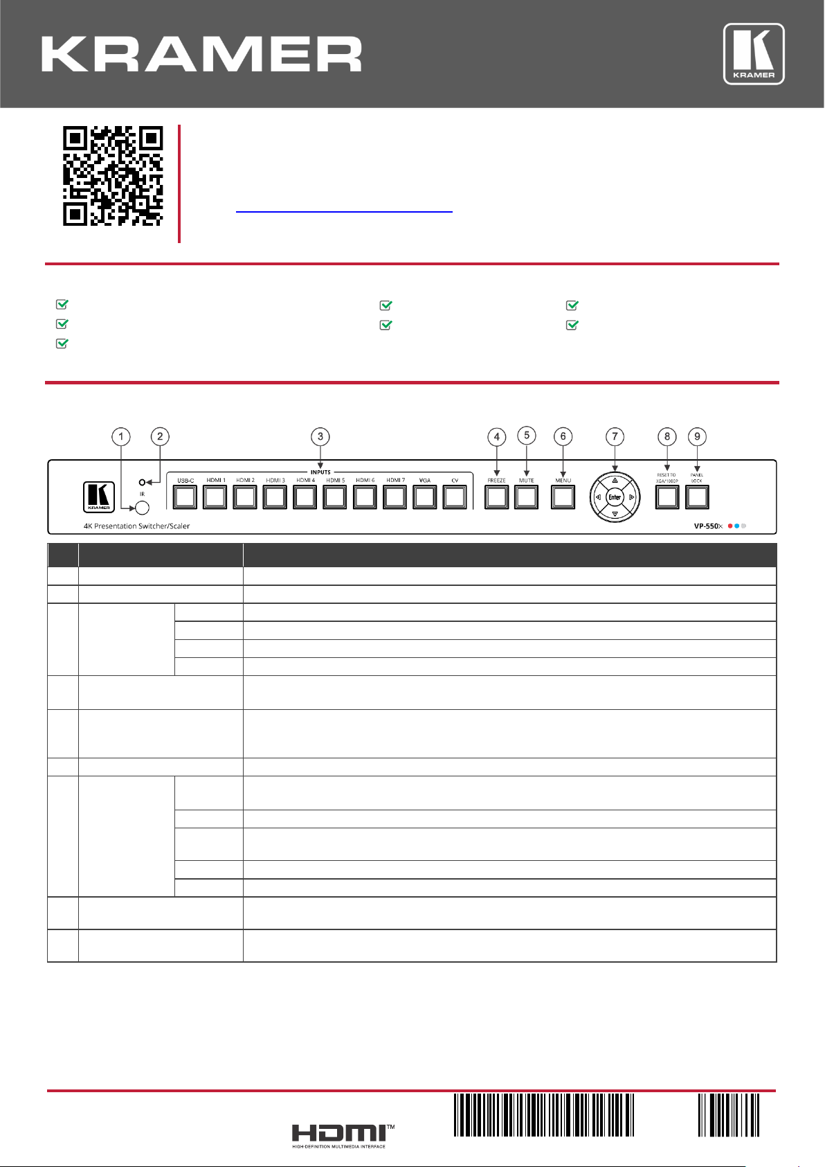
Step 2: Get to know your VP-550X
#
Feature
Function
1
IR Receiver
Receives signals from the remote-control transmitter.
2
IR LED
Lights when the unit accepts IR remote commands.
3
Input Selector
Buttons
USB-C
Press to select a USB-C source.
HDMI
Press to select the HDMI input (from HDMI 1 to HDMI 7).
VGA
Press to select the computer graphics input.
CV
Press to select the composite video input.
4
FREEZE Button
Press to freeze/unfreeze the output video image.
Not applicable when in video bypass mode.
5
MUTE Button
Press to toggle between muting (blocking out the sound) and enabling the audio output (both
line and speakers).
Muting the audio is not applicable when in audio bypass mode.
6
MENU Button
Press to enter/exit the on-screen display (OSD) menu.
7
Navigation
Buttons
Press to decrease numerical values or select from several definitions.
When not within the OSD menu mode, press to decrease the output volume.
Press to move up the menu list.
Press to increase numerical values or select from several definitions.
When not within the OSD menu mode, press to increase the output volume.
Press to move down the menu list.
Enter
Press to accept changes and change the SETUP parameters.
8
RESET TO XGA/1080p
Button
Press and hold for about 5 seconds to toggle resetting the video resolution to XGA or 1080p.
9
PANEL LOCK Button
Press and hold for about 5 seconds to lock/unlock the front panel buttons (panel locking
options are configurable).
Page 2
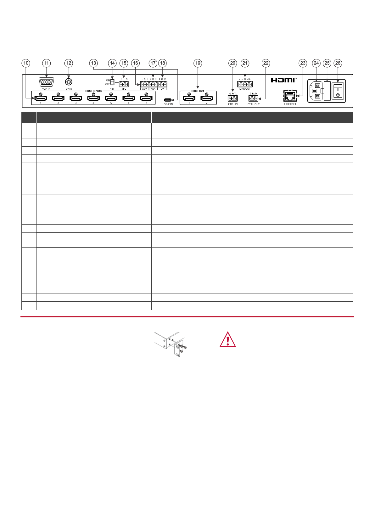
#
Feature
Function
10
HDMI INPUT Connectors
Connect to an HDMI source (from 1 to 7).
You can connect Step-in devices to inputs 1 and 2.
11
VGA 15-pin HD Connector
Connect to a computer graphics source.
12
CV IN RCA Connector
Connect to a composite video source.
13
USB-C IN Connector
Connect to a USB-C port, charging up to 18W.
14
48V MIC Switch
Move up (ON) to select a condenser type microphone; down (OFF) to select
a dynamic-type microphone.
15
MIC 3-pin Terminal Block Connector
Connect to a microphone source.
16
AUX 3-pin Terminal Block Connector
Connect to an auxiliary source.
17
VGA 3-pin Terminal Block Connector
(audio signal related to VGA IN)
Connect to the analog audio associated with the computer graphics source.
18
CV 3-pin Terminal Block Connector
(audio signal related to CV IN)
Connect to the analog audio associated with the composite video source.
19
HDMI OUT Connectors
Connect to HDMI acceptors (from 1 to 2).
20
CTRL IN 3-pin Terminal Block Connector
Connect to a PC or remote controller to control VP-550X via RS-232 Protocol
commands.
21
LINE OUT Balanced Stereo 5-pin Terminal
Block Connector
Connect to a balanced stereo analog audio acceptor.
22
CTRL OUT 3-pin Terminal Block
Connectors
Connect to an acceptor (for example, a display) to control it via RS-232
Protocol 3000 commands.
23
ETHERNET Connector
Connects to the PC or other Serial Controller through computer networking.
24
Mains Socket
Connect the mains power cord.
25
Mains Fuse Holder
Fuse for protecting the device.
26
Power Switch
Switch for turning the unit ON or OFF.
Step 3: Mount VP-550X
To rack mount the machine, attach both rack
ears (by removing the screws from each side of
the machine and replacing those screws through
the rack ears) or place the machine on a table.
• Ensure that the environment (e.g., maximum ambient
temperature & air flow) is compatible for the device.
• Avoid uneven mechanical loading.
• Appropriate consideration of equipment nameplate ratings
should be used for avoiding overloading of the circuits.
• Reliable earthing of rack-mounted equipment should be
maintained.
Page 3
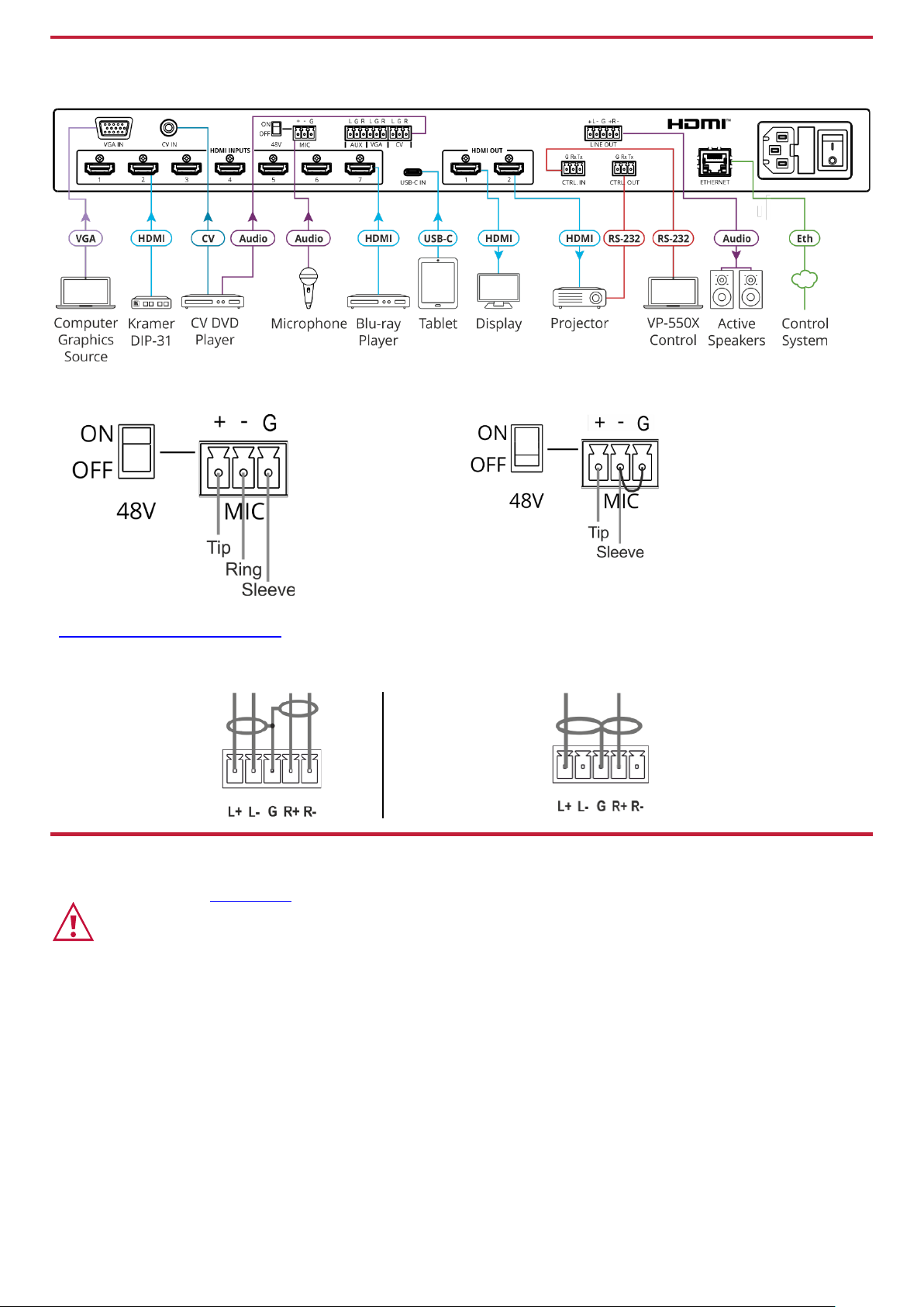
Step 4: Connect inputs and outputs
Always switch OFF the power on each device before connecting it to your VP-550X.
Condenser Microphone Pinout
Dynamic Microphone Pinout
For optimum range and performance use the recommended Kramer cables available at
www.kramerav.com/product/VP-550X.
Connecting the audio output
To a balanced stereo
audio acceptor:
To an unbalanced stereo
audio acceptor:
Step 5: Connect power
Connect the power cord to VP-550X and plug it into the mains electricity.
Safety Instructions (See www.kramerav.com for updated safety information)
Caution:
• For products with relay terminals and GPI\O ports, please refer to the permitted rating for an external connection, located next to the terminal or in the User Manual.
• There are no operator serviceable parts inside the unit.
Warning:
• Use only the power cord that is supplied with the unit.
• Disconnect the power and unplug the unit from the wall before installing.
• Do not open the unit. High voltages can cause electrical shock! Servicing by qualified personnel only.
• To ensure continuous risk protection, replace fuses only according to the rating specified on the product label which located on the bottom of the unit.
Page 4
Step 6: Operate VP-550X
Operate VP-550X:
• Remotely, by RS-232 serial
commands transmitted by a touch
screen system, PC, or other serial
controller.
• Using the embedded webpages
via the Ethernet
• Remotely, using the IR remote
control transmitter.
• Via the front panel buttons.
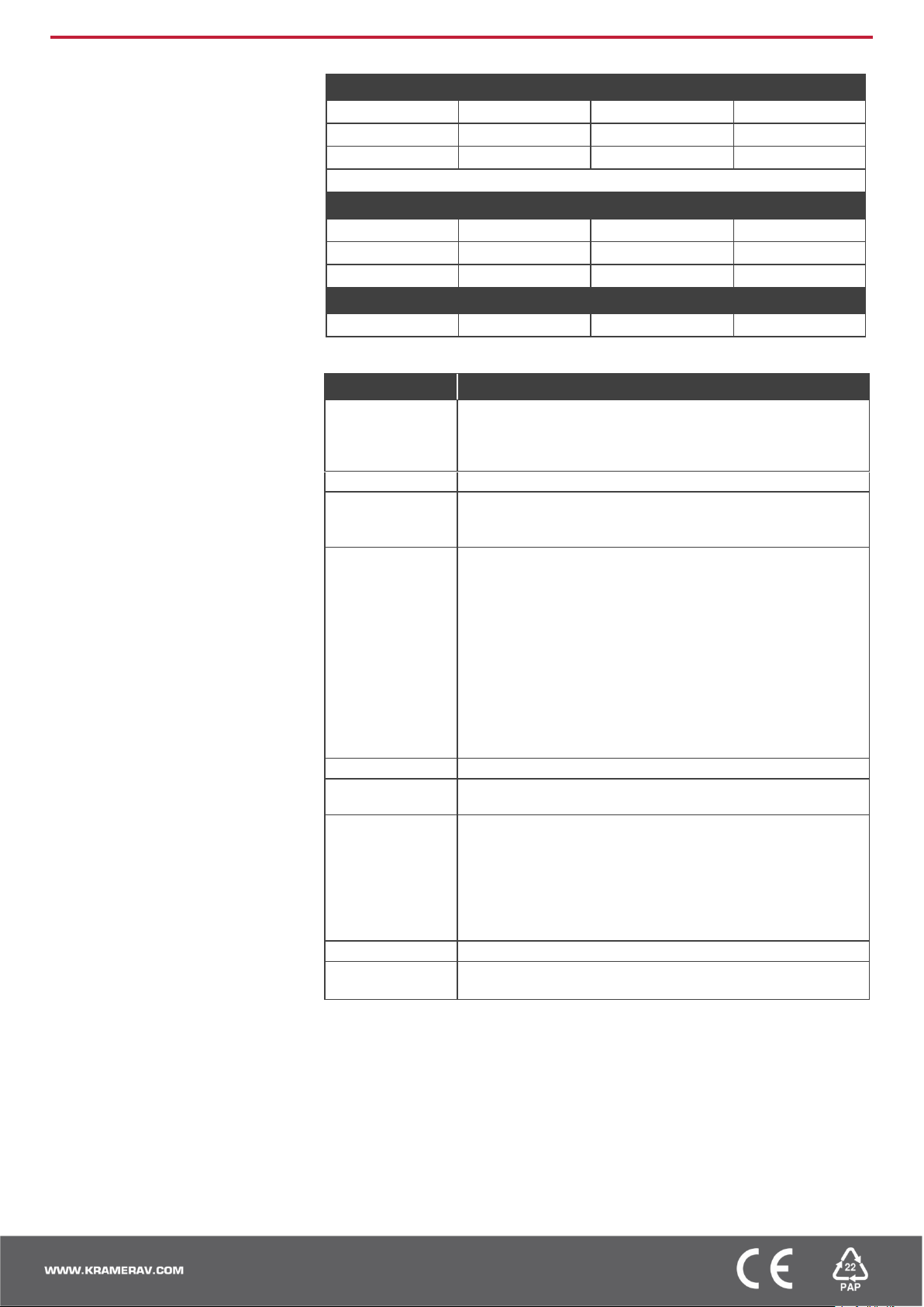
RS-232 Control / Protocol 3000
Baud Rate:
115,200
Parity:
None
Data Bits:
8
Command Format:
ASCII
Stop Bits:
1
Example: (route input HDMI 2 to the outputs): #ROUTE1,1,2<CR>
Default Ethernet Parameters
IP Address:
192.168.1.39
UDP Port #:
50000
Subnet mask:
255.255.0.0
TCP Port #:
5000
Gateway:
192.168.0.1
Authentication
User/Password
Admin/Admin
• Via the OSD menu buttons using the front panel navigation buttons.
OSD Menu Item
Function
Picture
Set the Contrast brightness and color.
For VGA: adjust the phase, clock horizontal and vertical
position.
For video: adjust the hue, sharpness, and noise reduction.
Input
Select the input.
Output
Define image size.
Enable or disable bypass mode.
Select the output resolution.
Audio
Set the input volume for each input individually.
Set the output volume.
Set delay time.
Enable or disable DRC and loudness.
Mute/unmute the output audio.
Set the audio source for each input to analog or embedded, or
select automatically.
Define microphone settings: mic mode, depth, trigger, attack
time, hold time, and release time.
Adjust mic volume.
Adjust equalizer level per bandwidth.
Enable/bypass DSP.
OSD
Define OSD position, timeout timer, transparency, and display.
EDID Manage
For each input, acquire the EDID from a selected output or use
a default EDID value.
Advanced
Define Ethernet parameters.
Set HDCP modes.
AUTO sync off option.
Define auto switch mode.
Set Lock mode behavior.
Enable/disable daily reset.
View device lifetime.
Info.
View the input and output information, and firmware version.
Factory
Perform full factory reset.
Perform soft reset, excluding Ethernet parameters.
The terms HDMI, HDMI High-Definition Multimedia Interface, and the HDMI Logo are trademarks or registered trademarks of HDMI Licensing Administrator, Inc.
 Loading...