

Page 1
VP-440X Quick Start
P/N:
2900- 301233QS
Rev:
1
Scan for full manual
VP-440X Quick Start Guide
This guide helps you install and use your VP-440X for the first time.
Go to www.kramerav.com/downloads/VP-440X to download the latest user manual and check if firmware
upgrades are available.
Step 1: Check what’s in the box
VP-440X 4K Presentation Switcher Scaler
1 Quick start guide
1 Power adapter and cord
4 Rubber feet
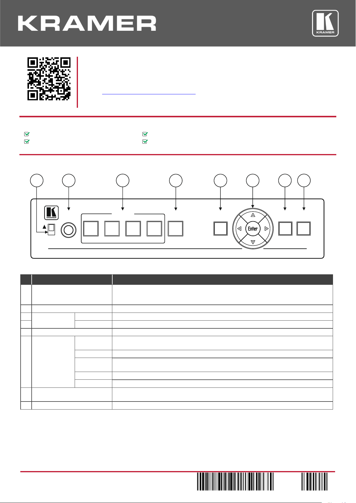
Step 2: Get to know your VP-440X
The terms HDMI, HDMI High-Definition Multimedia Interface, and the HDMI Logo are trademarks or registered trademarks of HDMI Licensing Administrator, Inc.
#
Feature
Function
1
48 V () Slide Switch
Slide up (48V) to select a condenser type microphone; slide down to select a dynamic
type microphone (we recommend that you slide down if a microphone is not connected to
the VP-440X).
2
MIC 6.3mm Jack
Connect to the microphone source.
3
Input Selector
Buttons
HDMI IN
Press to select the HDMI input (from 1 to 4).
4
PC IN
Press to select the computer graphics input.
5
MENU Button
Displays the OSD menu.
6
Navigation
Buttons
Press to decrease numerical values or select from several definitions.
When not in the OSD menu, press to reduce the output volume.
Press to move up the menu list values.
Press to increase numerical values or select from several definitions.
When not in the OSD menu, press to increase the output volume.
Press to move down the menu list.
ENTER
Press to accept changes and change the SETUP parameters.
7
RESET TO XGA/1080p Button
Press and hold for about 5 seconds to toggle the output resolution between XGA and
1080p, alternatively.
8
PANEL LOCK Button
Press and hold for about 5 seconds to lock/unlock the front panel buttons.
4K Presentation Switcher / Scaler
HDMI
TM
48 V
MENU
ESET TOR
XGA /1080 P
ANEL
OCK
P
L
VP-440X
ICM
NPC I
NI 2 NI 3
NI 4
NI 1
1 2 3 4 5 6 7 8
Page 2
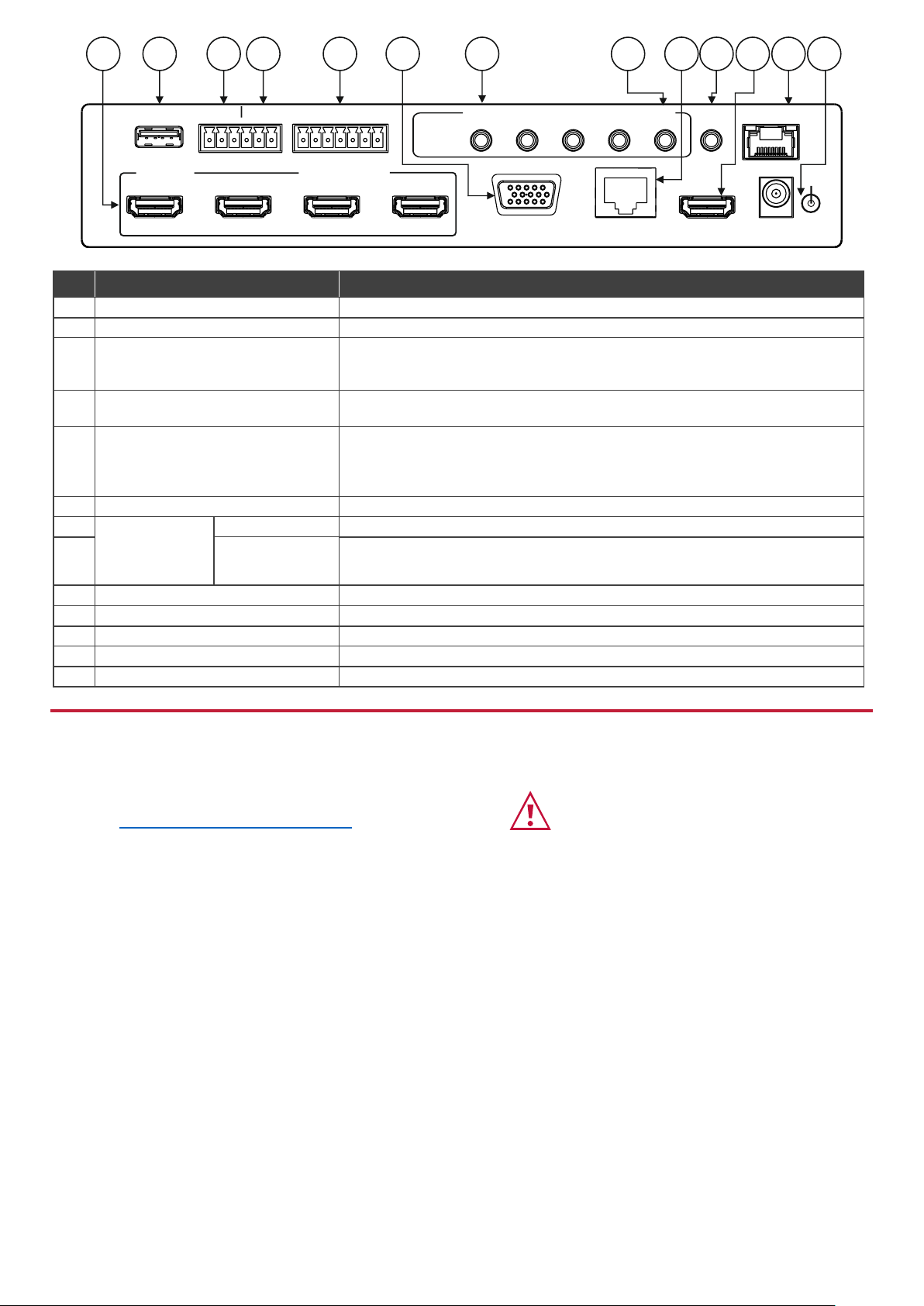
#
Feature
Function
9
Connect to an HDMI source (from 1 to 4).
10
PROG USB Type A Connector
Use to upgrade the firmware.
11
DATA (Tx, Rx, GND) Terminal Block
Connectors
Connect to a PC to Extend RS-232 signals via the HDBT OUT port, for example,
to control peripheral devices that are connected to the HDBT RECEIVER (e.g. a
projector connected to TP-780Rxr) via a PC or a serial controller.
12
CONTROL (Tx, Rx, GND) Terminal
Block Connector
Connect to a PC or serial controller to control the VP-440X or control the output
display (configurable).
13
SELECT 7-pin Terminal Block
Connector
HDMI 1 to HDMI 4 and PC: connect to contact closure switches (by momentary
contact between the desired pin and G pin) to select an input.
REMOTE: momentarily connect the pin to G, or connect an occupancy detector to
turn on/off the display (configurable for edge or for level triggering).
14
PC IN 15-pin HD Connector
Connect to the computer graphics source.
15
AUDIO INPUT
Unbalanced
Stereo 3.5 Mini
Jack
HDMI
Connect to the analog audio HDMI source (from 1 to 4).
16
PC
Connect to the analog audio computer graphics source.
17
HDBT OUT RJ-45 Connector
Connect to an HDBT receiver (for example, TP-780Rxr).
18
AUDIO OUT 3.5 Mini Jack
Connect to an unbalanced stereo audio acceptor.
19
HDMI OUT Connector
Connect to the HDMI acceptor.
20
ETHERNET Connector
Connects to the PC or other controller through computer networking.
21
5V DC
+5V DC connector for powering the unit.
Step 3: Install VP-440X
Install VP-440X using one of the following methods:
• Attach the rubber feet and place the unit on a flat surface.
• Mount the unit in a rack using the recommended rack adapter
(see www.kramerav.com/product/VP-440X).
• Ensure that the environment (e.g., maximum ambient temperature &
air flow) is compatible for the device.
• Avoid uneven mechanical loading.
• Appropriate consideration of equipment nameplate ratings should be
used for avoiding overloading of the circuits.
• Reliable earthing of rack-mounted equipment should be maintained.
• Maximum mounting height for the device is 2 meters.
UTHDBT O UTO
G
G
XR
PC
REMOTE
XT
UDIO
OUT
ADATA HDMI 2 HDMI 4
PC
HDMI
UDIO
NPUTS
A
I
NPC I 5V DC
THERNETE
PROG HDMI 3ONTROLC
G
XR
XT
HDMI 2
HDMI 3
HDMI 4
HDMI 1
HDMI
HDMI
TM
+
NI 2 NI 3
NI 4
NI 1
SELECT
9 10 11 12 13 1514 17 18 2016 2119
Page 3
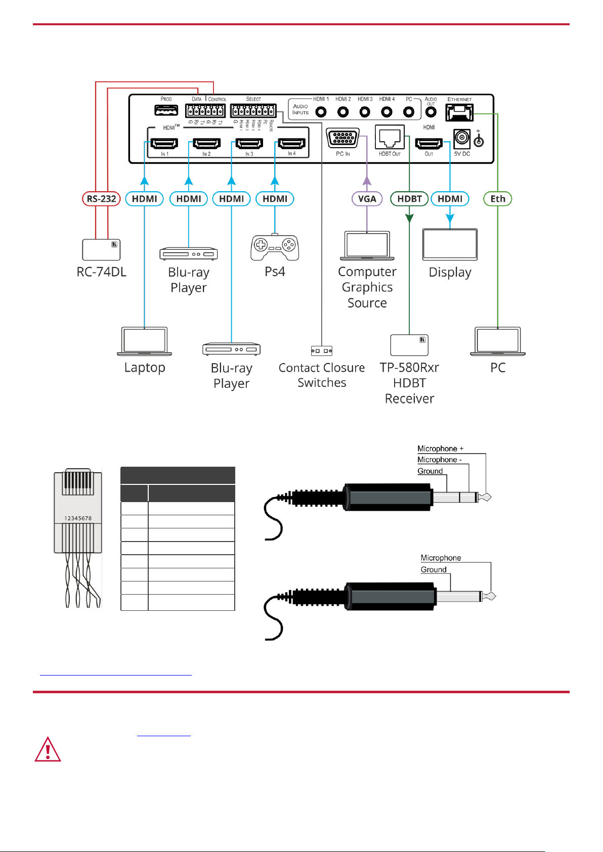
Step 4: Connect the inputs and outputs
Always switch OFF the power on each device before connecting it to your VP-440X. For best results, we recommend that you
always use Kramer high-performance cables to connect AV equipment to VP-440X.
RJ-45 Pinout:
Microphone Pinout:
For HDBT cables, it is recommended that the
cable ground shielding be connected/soldered
to the connector shield.
The microphone 6mm jack pinout for a condenser microphone
The microphone 6mm jack pinout for a dynamic microphone.
PIN EIA /TIA 568B
PIN
Wire Color
1
Orange / White
2
Orange
3
Green / White
4
Blue
5 Blue / White
6
Green
7
Brown / White
8
Brown
For optimum range and performance use the
recommended Kramer cables available at
www.kramerav.com/product/VP-440X.
Step 5: Connect the power
Connect the power adapter to VP-440X and plug it into the mains electricity.
Safety Instructions (See www.kramerav.com for updated safety information)
Caution:
• For products with relay terminals and GPI\O ports, please refer to the permitted rating for an external connection, located next to the terminal or in the User Manual.
• There are no operator serviceable parts inside the unit.
Warning:
• Use only the power cord that is supplied with the unit.
• Disconnect the power and unplug the unit from the wall before installing.
Page 4
Step 6: Operate and control the VP-440X
Operate VP-440X via:
• Input select and MENU front panel buttons (as well as reset and panel lock buttons).
• Remotely, by RS-232 serial commands transmitted by a touch screen system, PC, or other serial
controller.
• Embedded web pages via the Ethernet.
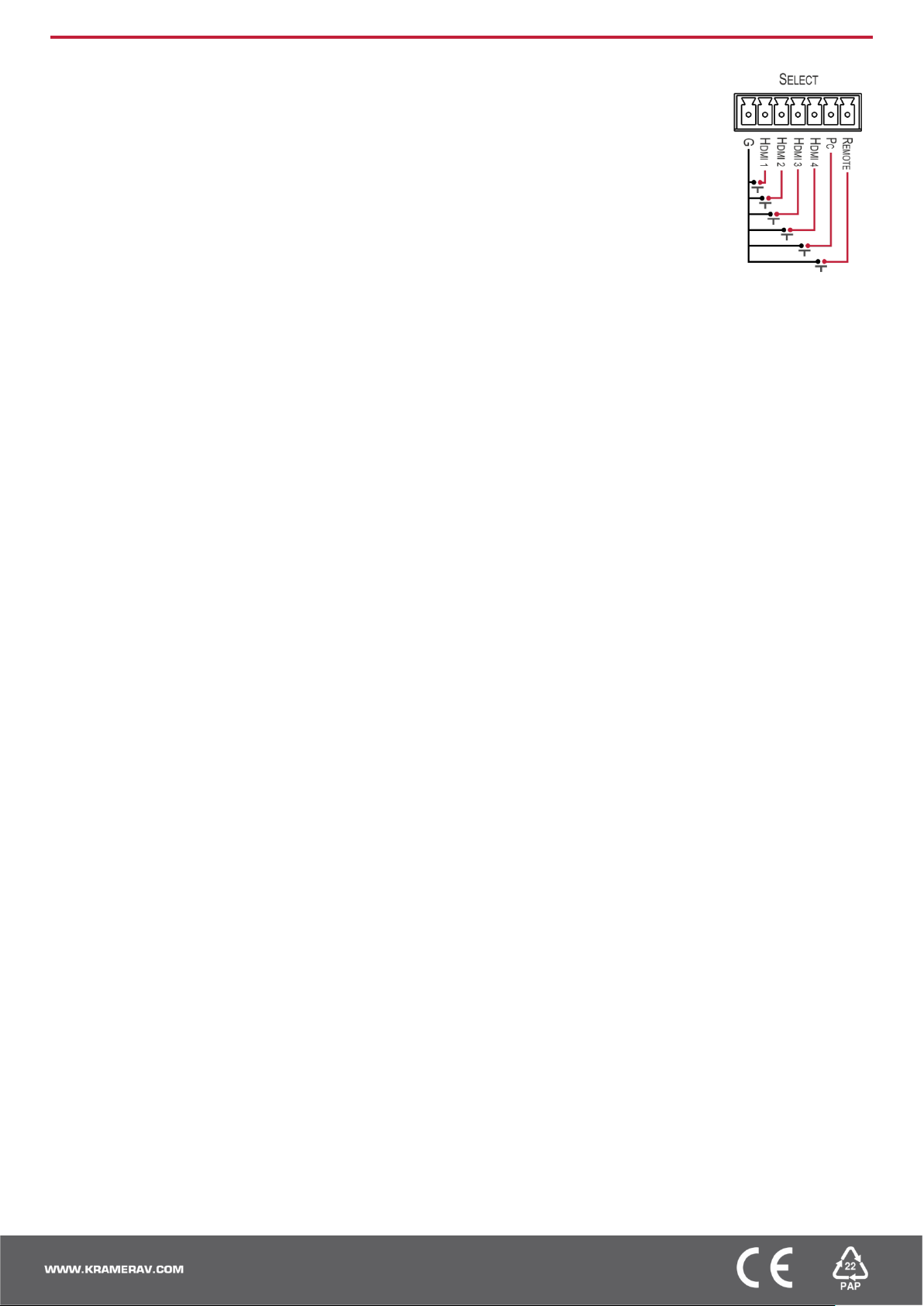
Select an input via:
• Front panel IN buttons.
• OSD menu.
• Contact closure terminal blocks to select an input remotely with the press of a button (HDMI 1
to HDMI 4, and PC).
• Embedded web pages.
Press the MENU button to configure and control the device via OSD menu:
• Set brightness, contrast, color, etc.
• Select resolution and aspect ratio.
• Select the input source, manage audio
input & output volume.
• Manage microphone settings and volume.
• Define OSD display.
• Configure HDCP behavior on input/output.
• Set auto-switching type and lock mode.
• Set Ethernet IP mode, IP address,
TCP/UDP ports, etc.
• Manage auto power down (Auto Sync Off).
• Manage EDID.
• View device information.
• Reset to factory default parameters.
 Loading...