

Page 1
VM-4DKT Quick Start
P/N:
2900- 301544QS
Rev:
1
Scan for full manual
VM-4DKT Quick Start Guide
This guide HELPS you install and use your VM-4DKT for the first time.
Go to www.kramerav.com/downloads/VM-4DKT to download the latest user manual and check if firmware
upgrades are available.
Step 1: Check what’s in the box
VM-4DKT 1:4 4K HDMI/DGKAT Distribution Amplifier Transmitter
4 Rubber feet
1 Quick start guide
1 Power cord and adapter
IMPORTANT NOTICE!
We highly recommend using only Kramer UNIKAT cables with these products. If using 3rd party shielded CAT-6A cables, both ends of the
shield must be soldered to the connectors for the products to function properly. Do not use any jumpers, unshielded wall plates or midspan cable connections. These extenders are not compatible with HDBaseT technologies. Prior to signal extension, ensure that the
extension line cable is lying straight and not coiled.
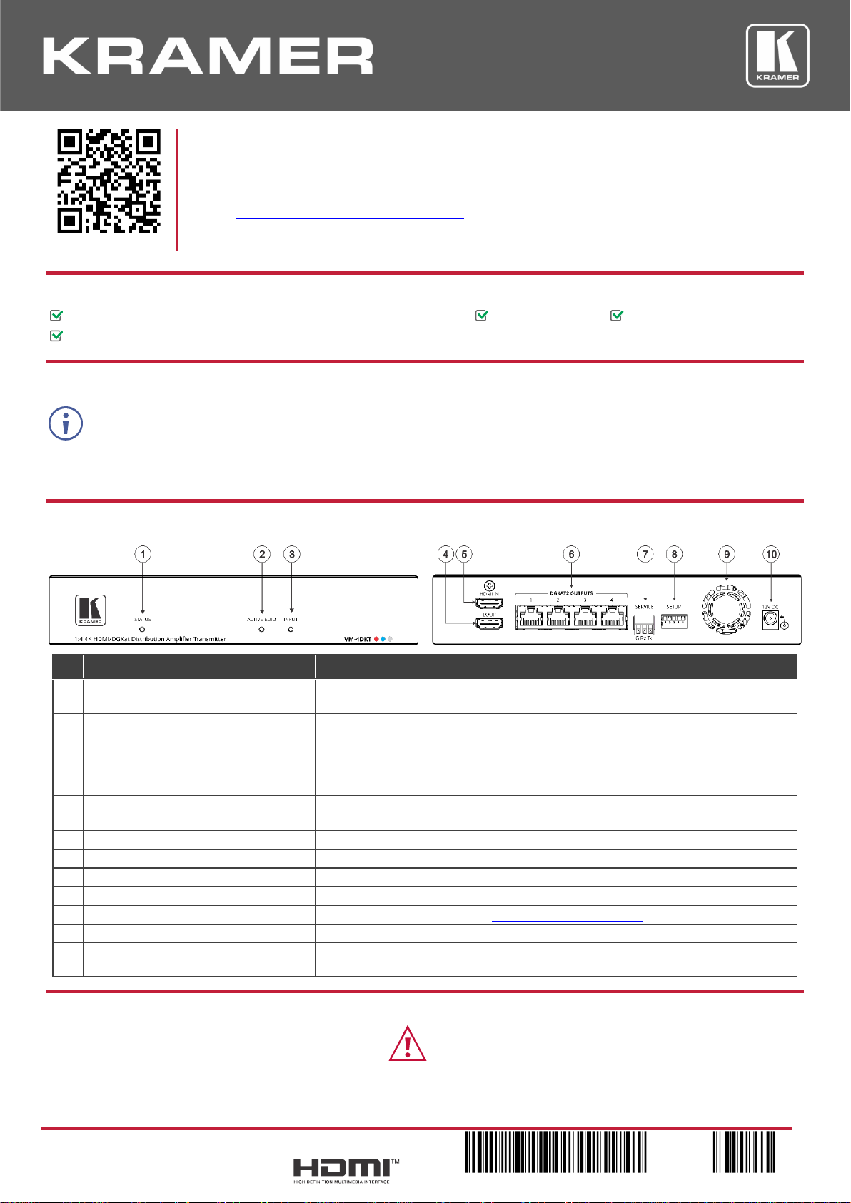
Step 2: Get to know your VM-4DKT
#
Feature
Function
1
STATUS LED
Red – Power up.
Green – Power is on.
2
ACTIVE EDID LED
The LED color indicates the active EDID type. When flashing, the state is in the
process of being activated.
Yellow – Default EDID.
Blue – Output-acquired EDID.
Green – Custom EDID.
3
INPUT LED
On – Input signal detected.
Flashing – Source connected, but no signal detected.
4
HDMI IN Connector
Connect to an HDMI source.
5
LOOP Connector
Connect to a local HDMI display.
6
DGKAT2 OUTPUTS Connectors (x4)
Connect to a DGKat-2.0 receiver (for example, PT-872xr) using twisted pair cable.
7
SERVICE 3-pin terminal block
Connect to a serial controller.
8
SETUP DIP-switches
Sets the device behavior (see Step 6: Operate VM-4DKT).
9
Fan Vent
For heat ventilation.
10
12V DC Power Connector
Connect the 12V DC power adapter into the device and then connect it to the
mains.
Step 3: Mount VM-4DKT
Install VM-4DKT using one of the following methods:
• Attach the rubber feet and place the unit on a flat
surface.
• Ensure that the environment (e.g., maximum ambient temperature & air flow) is
compatible for the device.
• Avoid uneven mechanical loading.
• Appropriate consideration of equipment nameplate ratings should be used for avoiding
overloading of the circuits.
• Reliable earthing of rack-mounted equipment should be maintained.
• Maximum mounting height for the device is 2 meters.
Page 2
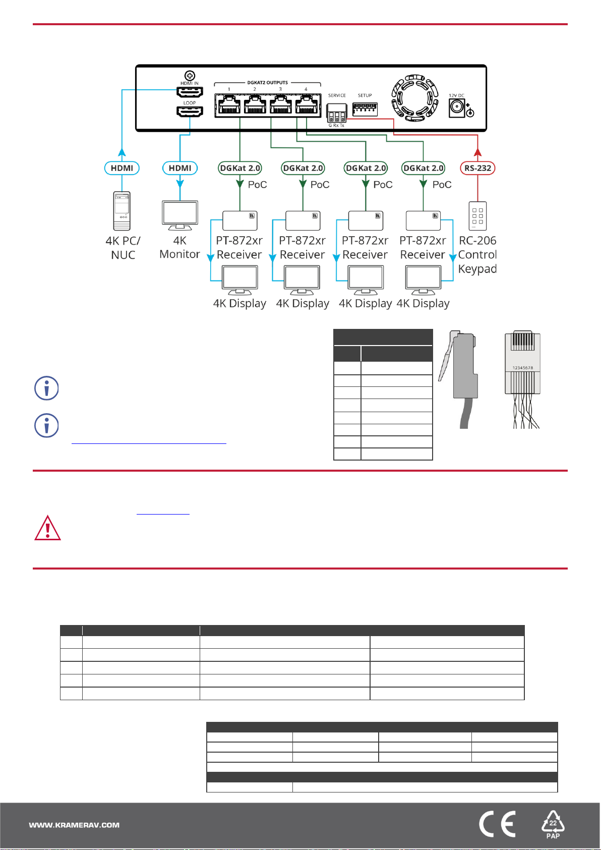
Step 4: Connect inputs and outputs
Always switch OFF the power on each device before connecting it to your VM-4DKT.
Wiring the RJ-45 Connectors
This section defines the DGKAT pinout, using a straight pin-to-pin cable
with RJ-45 connectors.
EIA /TIA 568B
PIN
Wire Color
1
Orange / White
The ground shielding must be connected/soldered to the
connector shield.
2
Orange
3
Green / White
4
Blue
To achieve specified extension distances, use the
recommended Kramer cables available at
www.kramerav.com/product/VM-4DKT.
Using third-party cables may cause damage!
5
Blue / White
6
Green
7
Brown / White
8
Brown
Step 5: Connect power
Connect the power adapter to the VM-4DKT and then plug it into the mains electricity.
Safety Instructions (See www.kramerav.com for updated safety information)
Caution:
• For products with relay terminals and GPI\O ports, please refer to the permitted rating for an external connection, located next to the terminal or in the User Manual.
• There are no operator serviceable parts inside the unit.
Warning:
• Use only the power cord that is supplied with the unit.
• Disconnect the power and unplug the unit from the wall before installing.
Step 6: Operate VM-4DKT
Set the VM-4DKT DIP-switches:
A DIP-switch that is down is on, up is off. Changes to the DIP-switches take effect immediately.
#
Function
Status
1
Active EDID source
ON (down) – Default EDID (default)
OFF (up) – 1st OUT EDID
2
EDID auto-acquire
OFF (up) – Auto-acquire enabled (default)
ON (down) – Auto-acquire disabled
3
Input HDCP appearance
OFF (up) – Active (default)
ON (down) – Inactive
4
Compression setup
OFF (up) – Standard (default)
ON (down) – High
5
RS-232 operation mode
OFF (up) – Normal operation mode (default)
ON (down) – Firmware upgrade mode.
Control the devices:
Operate remotely, by RS-232 serial
commands transmitted by PC, or
other serial controller.
RS-232 Control / Protocol 3000
Baud Rate:
115,200
Parity:
None
Data Bits:
8
Command Format:
ASCII
Stop Bits:
1
Example (get device model name): #model?<cr>
Factory Default Parameters
P3K command:
#factory<cr>
 Loading...