

Page 1

KRAMER ELECTRONIC S LTD.
USER MANUAL
MODEL:
VM-1 02 1N
1:20 Video Distributor
P/N: 2900-300429 Rev 1
Page 2
Page 3

VM-1021N – Contents
i
Contents
1 Introduction 1
2 Getting Started 2
2.1 Achieving the Best Performance 2
2.2 Safety Instructions 3
2.3 Recycling Kramer Products 3
3 Overview 4
4 Installing in a Rack 7
5 Connecting the VM-1021N 8
6 VM-1021N Technical Specifications 10
Figures
Figure 1: VM-1021N 1:20 Video Distributor Front Panel 5
Figure 2: VM-1021N 1:20 Video Distributor Rear Panel 6
Figure 3: Connecting the VM-1021N 8
Page 4

VM-1021N - Introduction
1
1 Introduction
Welcome to Kramer Electronics! Since 1981, Kramer Electronics has been
providing a world of unique, creative, and affordable solutions to the vast range of
problems that confront the video, audio, presentation, and broadcasting
professional on a daily basis. In recent years, we have redesigned and upgraded
most of our line, making the best even better!
Our 1,000-plus different models now appear in 14 groups that are clearly defined
by function: GROUP 1: Distribution Amplifiers; GROUP 2: Switchers and Routers;
GROUP 3: Control Systems; GROUP 4: Format/Standards Converters; GROUP 5:
Range Extenders and Repeaters; GROUP 6: Specialty AV Products; GROUP 7:
Scan Converters and Scalers; GROUP 8: Cables and Connectors; GROUP 9:
Room Connectivity; GROUP 10: Accessories and Rack Adapters; GROUP 11:
Sierra Video Products; GROUP 12: Digital Signage; GROUP 13: Audio; and
GROUP 14: Collaboration.
Congratulations on purchasing your Kramer VM-1021NN distribution amplifier that
is ideal for the following typical applications:
Broadcast, production, or presentation systems requiring high-quality signal
distribution
Schools, retail, sports bars, other point-of-sale and CCTV applications
Computer RGB or component video distribution
Page 5

2
VM-1021N - Getting Started
Go to http://www.kramerelectronics.com/support/product_downloads.asp
to check for up-to-date user manuals, application programs, and to check if
firmware upgrades are available (where appropriate).
This equipment is to be used only inside a building. It may only be
connected to other equipment that is installed inside a building.
i
!
2 Getting Started
We recommend that you:
Unpack the equipment carefully and save the original box and packaging
materials for possible future shipment
Review the contents of this user manual
2.1 Achieving the Best Performance
To achieve the best performance:
Use only good quality connection cables (we recommend Kramer high-
performance, high-resolution cables) to avoid interference, deterioration in
signal quality due to poor matching, and elevated noise levels (often
associated with low quality cables)
Do not secure the cables in tight bundles or roll the slack into tight coils
Avoid interference from neighboring electrical appliances that may adversely
influence signal quality
Position your Kramer VM-1021N away from moisture, excessive sunlight and
dust
Page 6

VM-1021N - Getting Started
3
Caution:
There are no operator serviceable parts inside the unit
Warning:
Use only the power cord that is supplied with the unit
Warning:
Do not open the unit. High voltages can cause
electrical shock! Servicing by qualified personnel only
Warning:
Disconnect the power and unplug the unit from the wall
before installing
!
2.2 Safety Instructions
2.3 Recycling Kramer Products
The Waste Electrical and Electronic Equipment (WEEE) Directive 2002/96/EC
aims to reduce the amount of WEEE sent for disposal to landfill or incineration by
requiring it to be collected and recycled. To comply with the WEEE Directive,
Kramer Electronics has made arrangements with the European Advanced
Recycling Network (EARN) and will cover any costs of treatment, recycling and
recovery of waste Kramer Electronics branded equipment on arrival at the EARN
facility. For details of Kramer’s recycling arrangements in your particular country
go to our recycling pages at http://www.kramerelectronics.com/support/recycling/.
Page 7

4
VM-1021N - Overview
3 Overview
The VM-1021N is a high-performance distribution amplifier for composite or SDI
video signals. It provides controls to compensate for signal losses inherent in long
cable runs.
The VM-1021N is a full broadcast, state-of-the-art, 1:20 video distribution amplifier
designed for studio and other demanding applications. The unit splits a single
input source into twenty identical outputs with no discernible signal degradation.
The outputs are divided into 4 sets of five each, where each set may be
individually trimmed (level and EQ) for maximal flexibility. The machine may be
used to distribute analog or SD-SDI video signals, composite or single component.
The unit features:
High bandwidth of 350MHz (-3dB)
Grouped level (gain) and EQ (peaking) controls
Looping inputs
Selectable input signal termination
DC coupling
Standard 19” rack mount size of 1U
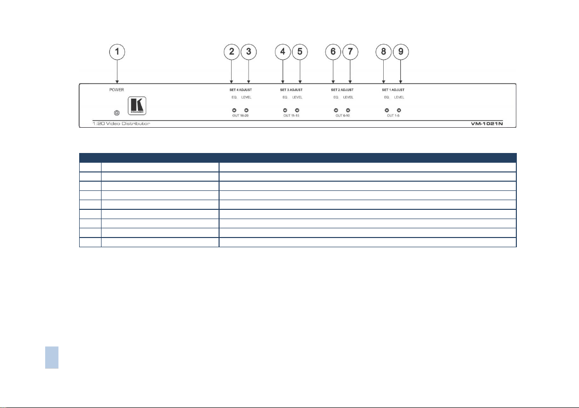
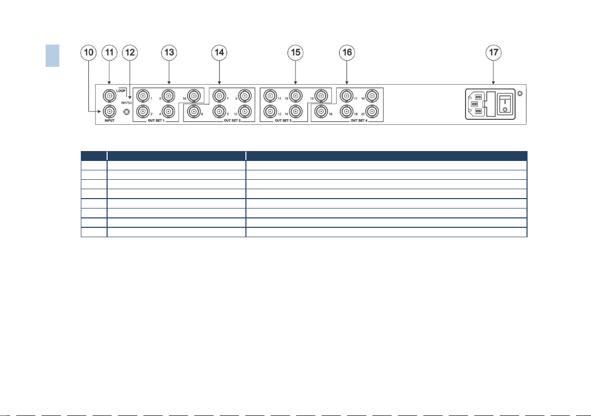
Figure 1 and Figure 2 define the unit.
Page 8
VM-1021N - Overview
5
VM-1021N – Overview
5
#
Feature
Function
1
POWER LED
Illuminates when the device is turned on
2
SET 4 ADJUST EQ Trimmer
Controls cable equalization of SET 4 video outputs 16-20
3
SET 4 ADJUST LEVEL Trimmer
Controls level of SET 4 video outputs 16-20
4
SET 3 ADJUST EQ Trimmer
Controls cable equalization of SET 3 video outputs 11-15
5
SET 3 ADJUST LEVEL Trimmer
Controls level of SET 3 video outputs 11-15
6
SET 2 ADJUST EQ Trimmer
Controls cable equalization of the SET 2 video outputs 6-10
7
SET 2 ADJUST LEVEL Trimmer
Controls level of SET 2 video outputs 6-10
8
SET 1 ADJUST EQ Trimmer
Controls cable equalization of the SET 1 video outputs 1-5
9
SET 1 ADJUST LEVEL Trimmer
Controls level of the SET 1 video outputs 1-5
Figure 1: VM-1021N 1:20 Video Distributor Front Panel
Page 9
6
VM-1021N - Overview
#
Feature
Function
10
INPUT BNC Connector
Connects to a composite/component/ analog sync video source
11
LOOP BNC Connector
Selects “75Ω“ or “HI-z” impedance when pressed (for looping select "Hi-z")
12
IN=75Ω Button
Provides video looping capability to increase number of outputs
13
OUT SET 1 BNC Connectors (1-5)
SET 1 of 5 amplified buffered and clamped video outputs 1-5
14
OUT SET 2 BNC Connectors (6-10)
SET 2 of 5 amplified buffered and clamped video outputs 6-10
15
OUT SET 3 BNC Connectors (11-15)
SET 3 of 5 amplified buffered and clamped video outputs 11-15
16
OUT SET 4 BNC Connectors (16-20)
SET 4 of 5 amplified buffered and clamped video outputs 16-20
17
Power Connector
AC connector, fuse and power switch enabling power supply to the unit
6
VM-1021N – Overview
Figure 2: VM-1021N 1:20 Video Distributor Rear Panel
Page 10
VM-1021N - Installing in a Rack
7
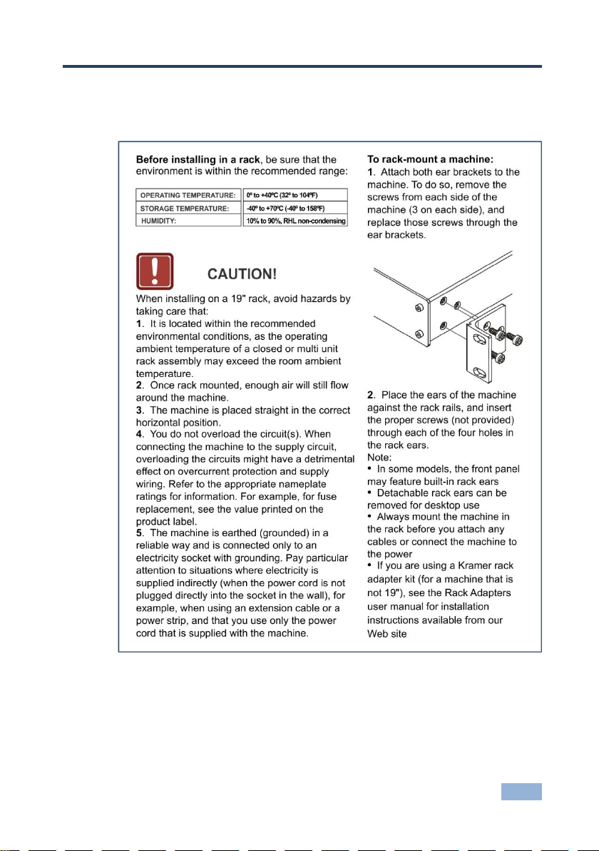
4 Installing in a Rack
This section provides instructions for rack mounting the unit.
Page 11
8
VM-1021N - Connecting the VM-1021N
Always switch off the power to each device before connecting it to your
VM-1021N. After connecting your VM-1021N, connect its power and
then switch on the power to each device.
i
5 Connecting the VM-1021N
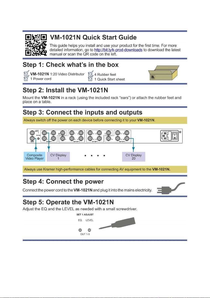
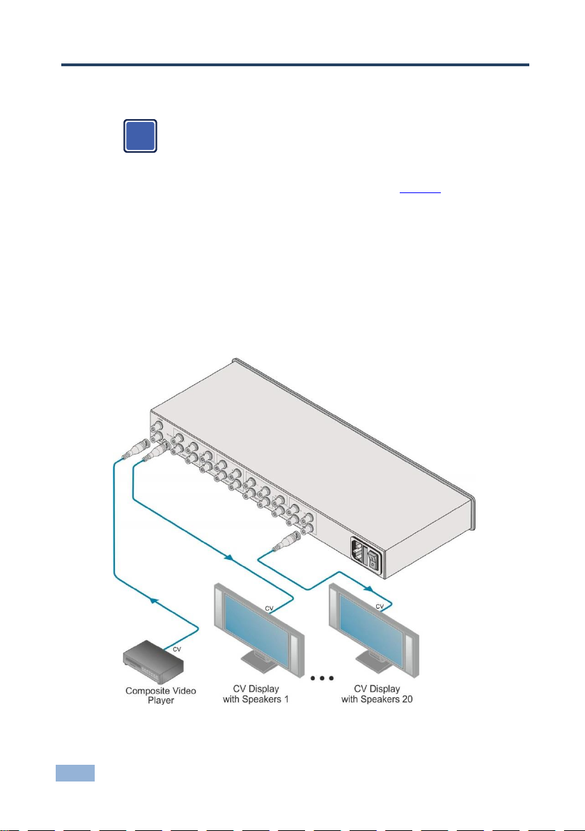
To connect the VM-1021N as illustrated in the example in Figure 3:
1. Connect a video source to the INPUT BNC connector (for example, a
composite video player).
2. Connect the OUT SET BNC connectors to up to 20 video acceptors, 4 sets
of 5 devices (for example, composite video displays with speakers).
3. Adjust the equalization (EQ) and level (LEVEL) for each of the 4 sets of 5
devices as needed.
Figure 3: Connecting the VM-1021N
Page 12

VM-1021N - Connecting the VM-1021N
9
Note:
Terminate unused inputs to 75Ω, and terminate active inputs at the
connecting source
The output signal format must match the input signal format (for example, if
the input is composite, the output is composite)
All signal cables to each device should be of equal length (for example, the
R,G,B cables between a camera and the amplifier should be of equal length)
Page 13
10
VM-1021N - VM-1021N Technical Specifications
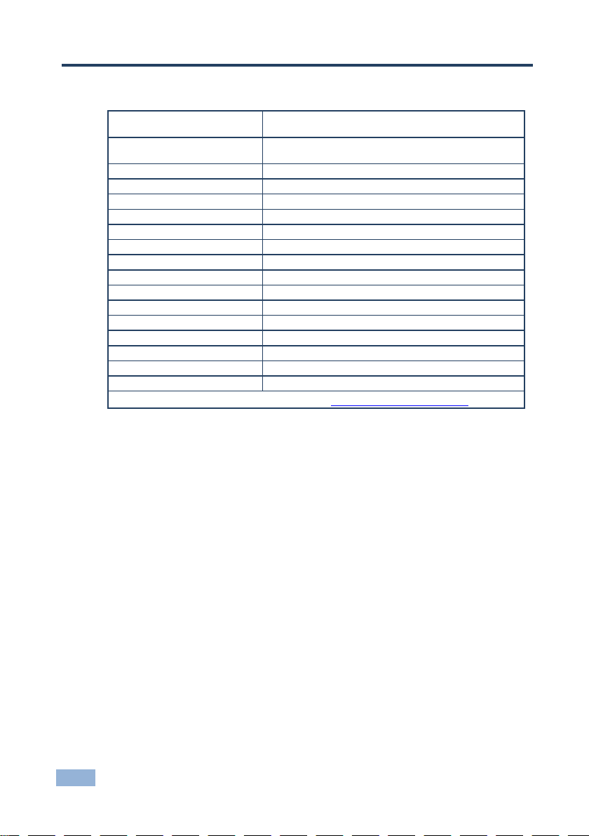
INPUT:
1 composite video or a single component, looping,
1Vpp/75Ω on BNC connectors with termination switch
OUTPUTS:
20 composite/component video, 1Vpp/75Ω on BNC
connectors
VIDEO BANDWIDTH(-3dB):
350MHz
DIFF. GAIN:
0.1%
DIFF. PHASE:
0.07Deg
K-FACTOR:
<0.05%
VIDEO S/N RATIO:
74dB
CONTROL:
Level: -1.1dB to + 2.7dB; EQ.: 0 to 2.9dB @4.4MHz
NON-LINEARITY:
0.1%
COUPLING:
DC
POWER SOURCE:
100-240V AC, 50/60Hz, 6.7VA
OPERATING TEMPERATURE:
0° to +40°C (32° to 104°F)
STORAGE TEMPERATURE:
-40° to +70°C (-40° to 158°F)
HUMIDITY:
10% to 90%, RHL non-condensing
DIMENSIONS:
19" x 7" x 1U W, D, H, rack mountable
WEIGHT:
2.6kg (5.7lbs) approx.
INCLUDED ACCESSORIES:
Power cord
Specifications are subject to change without notice at http://www.kramerelectronics.com
6 VM-1021N Technical Specifications
Page 14
Page 15
For the latest information on our products and a list of Kramer distributors, visit
our Web site where updates to this user manual may be found.
We welcome your questions, comments, and feedback.
Web site: www.kramerelectronics.com
E-mail: [email protected]
SAFETY WARNING
Disconnect the unit from the power
supply before opening and servicing
P/N:
2900-300429
Rev:
1
!
 Loading...