

Page 1
TP-789R Quick Start (P/N: 2900-300966QS REV 1)
P/N:
2900- 300966QS
Rev:
1
Scan for full manual
TP-789R Quick Start Guide
This guide helps you install and use your TP-789R for the first time.
Go to www.kramerav.com/downloads/TP-789R to download the latest user manual and check if firmware
upgrades are available.
Step 1: Check what’s in the box
TP-789R HDMI Line Receiver
4 Rubber feet
1 Quick start guide
1 Power adapter and cord
1 Bracket set
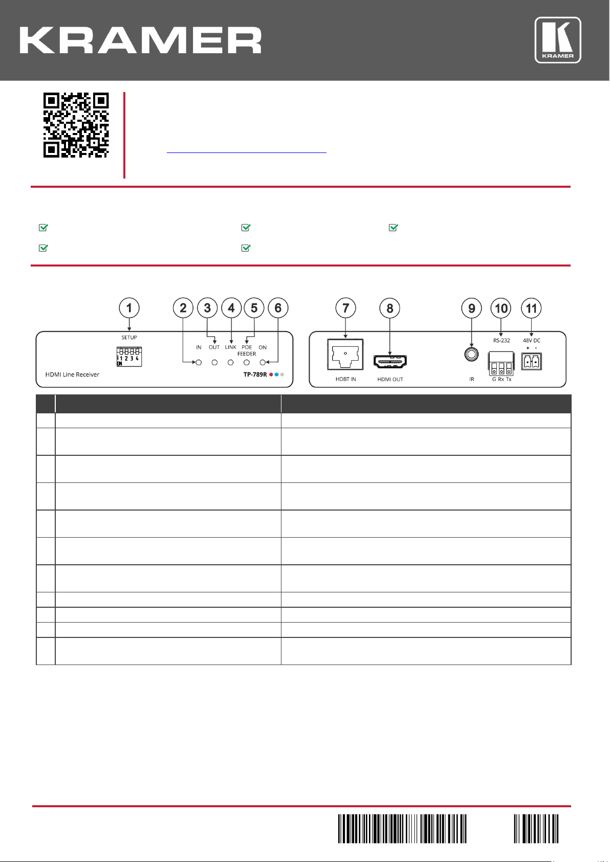
Step 2: Get to know your TP-789R
#
Feature
Function
1
SETUP DIP-switches
Set the operation DIP-switches.
2
IN LED
Lights green when an active far-end source device input signal is
detected.
3
OUT LED
Lights green when an active sink (acceptor) output signal is detected
via the HDBT link.
4
LINK LED
Lights green when an HDBT link is established with the HDBaseT
transmitter.
5
POE FEEDER LED
Lights green when the device is feeding PoE power to the HDBT
connected transmitter.
6
ON LED
Lights green when the device receives power either from the power
supply unit or by PoE.
7
HDBT IN RJ-45 Connector
Connect to the RJ-45 HDBT OUT connector on a transmitter (for
example, WP-20, TP-780T).
8
HDMI® OUT Connector
Connect to an HDMI acceptor.
9
IR 3.5mm Mini Jack Connector
Connect to an external infrared emitter / sensor.
10
RS-232 (G, Rx, Tx) 3-pin Terminal Block Connector
Connects to an RS-232 port for serial link extension to a transmitter.
11
48V DC Power Terminal Block Connector
If TP-789R provides PoE, connect it to the Kramer power adapter.
If it accepts PoE, no power connection is needed.
The terms HDMI, HDMI High-Definition Multimedia Interface, and the HDMI Logo are trademarks or registered trademarks of HDMI Licensing Administrator, Inc.
Page 2
Step 3: Install TP-789R
Install TP-789R using one of the following methods:
• Attach the rubber feet and place the unit on a flat surface.
• Fasten a bracket (included) on each side of the unit and attach it to a flat surface.
For more information go to
www.kramerav.com/downloads/TP-789R.
• Mount the unit in a rack using the recommended rack adapter
(see www.kramerav.com/product/TP-789R).
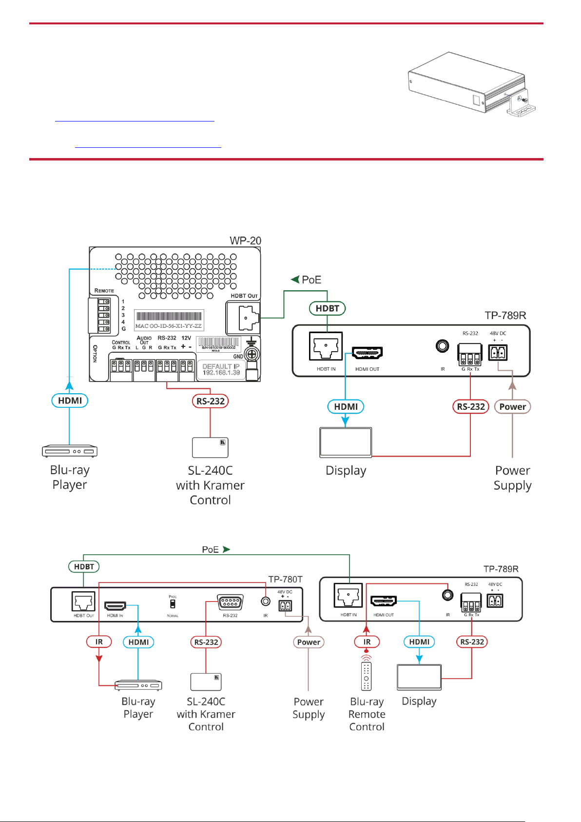
Step 4: Connect the inputs and outputs
Always switch OFF the power on each device before connecting it to your TP-789R. For best results, we recommend that you
always use Kramer high-performance cables to connect AV equipment to TP-789R.
Connecting TP-789R as a power provider:
Connecting TP-789R as a power acceptor:
Page 3

RJ-45 Pinout:
DIP-Switch Settings
For the Ethernet connector, see the wiring diagram
below:
All DIP-switches are set to OFF (up) by default.
Changes to DIP-switch 4 only take effect after
rebooting the device.
PIN EIA /TIA 568B
PIN
Wire Color
#
Feature
Dip-switch Settings
1
Orange / White
1
Reserved
For future use.
2
Orange
2
Reserved
For future use. Set to OFF (up).
3
Green / White
3
IR
Frequency
OFF (up) – IR frequency is 38kHz.
ON (down) – Wide-range modulated IR frequency.
4
Blue
5
Blue / White
Set to OFF for backward compatibility
with 38kHz IR extension.
6
Green
7
Brown / White
4
FW
Upgrade
OFF – Normal operation mode.
ON – HDBT FW upgrade mode.
8
Brown
For optimum range and performance use the
recommended Kramer cables available at
www.kramerav.com/product/TP-789R.
When set to ON device operation is
disabled.
Step 5: Connect the power
When used as a PoE provider, connect the 48V DC power supply to TP-789R and plug it into the mains electricity (to also provide
power to a transmitter).
When accepting power from an HDBT transmitter via PoE there is no need to connect the 48V DC power supply.
Safety Instructions
Caution:
There are no operator serviceable parts inside the unit.
Warning:
Use only the Kramer Electronics power adapter that is provided with the unit.
Warning:
Disconnect the power and unplug the unit from the wall before installing.
See www.KramerAV.com for updated safety information.
Step 6: Upgrade the firmware
Upgrade the firmware by:
• Setting the DIP-switches.
• Loading the new firmware via
the RS-232 port on the
TP-789R.
RS-232 Pass-through Data
Baud Rate:
115,200
Data Bits:
8
Stop Bits:
1
Parity:
None
Command Format:
ASCII
Page 4

Technical Specifications
Input
HDBT
On an RJ-45 connector
Output
HDMI
On a female HDMI connector
Ports
RS-232
On a 3-pin terminal block connector for serial link extension
IR
On a 3.5mm mini-jack connector for IR link extension
Video
Max Bandwidth
10.2Gbps
Max Resolution
4K@60 (4:2:0)
Compliance
HDMI 2.0 and HDCP 2.2
Extension Range
4k@60 (4:2:0)
Up to 40m (130ft)
Full HD (1080p@60Hz)
Up to 70m (230ft)
Extended RS-232
Baud Rate
300 to 115200 baud
Extended IR
Frequency
20kHz to 100kHz
Direction
Bidirectional (IR sensor or emitter)
Controls
Front Panel
IN, OUT, LINK, POE FEEDER and ON LED indicators
Rear Panel
DIP-switches
Power
Consumption
48V DC, 350mA
Source
48V DC, 1.36A
Environmental
Conditions
Operating Temperature
0° to +40°C (32° to 104°F)
Storage Temperature
-40° to +70°C (-40° to 158°F)
Humidity
10% to 90%, RHL non-condensing
Regulatory
Compliance
Safety
CE
Environmental
RoHs, WEEE
Enclosure
Size
Tool
Type
Aluminum
Cooling
Convection ventilation
General
Net Dimensions (W, D, H), each
12cm x 7.2cm x 2.4cm
(4.7" x 2.8" x 0.94")
Shipping Dimensions (W, D, H)
15.7cm x 12cm x 8.7cm
(6.2" x 4.7" x 3.4")
Net Weight, each
0.2kg (0.44bs) approx.
Shipping Weight
0.72kg (1.6lbs) approx.
Accessories
Included
1 Power adapter, 1 power cord and 1 bracket set per device
Specifications are subject to change without notice at www.kramerav.com
 Loading...