

Page 1

USER MANUAL
MODELS:
TP-752T
2-Wire Extra Range HD Transmitter
TP-752R
2-Wire Extra Range HD Receiver
P/N: 2900-301041 Rev 1 www.KramerAV.com
Page 2

Kramer Electronics Ltd.
TP-752T / TP-752R – Contents
i
Contents
Introduction 1
Getting Started 1
Overview 2
Typical Applications 3
Defining the 2-Wire Extra Range HD Transmitter 4
Mounting TP-752T/TP-752R 6
Connecting the TP-752T/TP-752R 7
Grounding the TP-752T/TP-752R 8
Connecting the Output to a Balanced/Unbalanced Stereo Audio Acceptor 9
Connecting to TP-752T/TP-752R via RS-232 9
Setting the Baud Rate 9
Technical Specifications 10
Page 3

Kramer Electronics Ltd.
TP-752T / TP-752R – Introduction
1
Go to
application programs, and to check if firmware upgrades are available (where appropriate).
This equipment is to be used only inside a building. It may only be connected to other
equipment that is installed inside a building.
Caution:
Warning:
Introduction
Welcome to Kramer Electronics! Since 1981, Kramer Electronics has been providing a world
of unique, creative, and affordable solutions to the vast range of problems that confront the
video, audio, presentation, and broadcasting professional on a daily basis. In recent years, we
have redesigned and upgraded most of our line, making the best even better!
Getting Started
We recommend that you:
• Unpack the equipment carefully and save the original box and packaging materials for
possible future shipment.
• Review the contents of this user manual.
www.kramerav.com/downloads/TP-752T to check for up-to-date user manuals,
Achieving the Best Performance
• Use only good quality connection cables (we recommend Kramer high-performance,
high-resolution cables) to avoid interference, deterioration in signal quality due to poor
matching, and elevated noise levels (often associated with low quality cables).
• Do not secure the cables in tight bundles or roll the slack into tight coils.
• Avoid interference from neighboring electrical appliances that may adversely influence
signal quality.
• Position your Kramer TP-752T / TP-752R away from moisture, excessive sunlight and
dust.
Safety Instructions
• This equipment is to be used only inside a building. It may only be connected to other
equipment that is installed inside a building.
• For products with relay terminals and GPI\O ports, please refer to the permitted rating
for an external connection, located next to the terminal or in the User Manual.
• There are no operator serviceable parts inside the unit.
• Use only the power cord that is supplied with the unit.
• To ensure continuous risk protection, replace fuses only according to the rating
specified on the product label which located on the bottom of the unit.
Page 4

Kramer Electronics Ltd.
TP-752T / TP-752R – Introduction
2
TP
Recycling Kramer Products
The Waste Electrical and Electronic Equipment (WEEE) Directive 2002/96/EC aims to reduce
the amount of WEEE sent for disposal to landfill or incineration by requiring it to be collected
and recycled. To comply with the WEEE Directive, Kramer Electronics has made
arrangements with the European Advanced Recycling Network (EARN) and will cover any
costs of treatment, recycling and recovery of waste Kramer Electronics branded equipment on
arrival at the EARN facility. For details of Kramer’s recycling arrangements in your particular
country go to our recycling pages at www.kramerav.com/support/recycling
.
Overview
Congratulations on purchasing your Kramer TP-752T 2-Wire Extra Range HD Transmitter
and/or TP-752R 2-Wire Extra Range HD Receiver. TP-752T and TP-752R are a
high-performance transmitter and receiver pair that can extend 1080p (HD) HDMI signals over
distances of up to 600m (2000ft) using any 2-wire cabling. Both TP-752T and TP-752R
support diverse cabling and connector options for typical long distance and legacy
installations.
-752T and TP-752R are sold separately.
TP-752T and TP-752R provide exceptional quality, advanced and user-friendly operation, and
flexible control.
Exceptional Quality
• High Performance Extender – Reliable HDMI signal extension over distances of up to
600m (2000ft).
• Cascaded Signal Distribution – The TP-752T transmitter has an active, reclocking HDMI
output loop port for cascaded signal extenders or distributors, or local signal monitoring.
• Bidirectional RS-
232 Extension – Enabling device control, such as control of the display
from the source end, and control of a source from the display end.
Advanced and User-friendly Operation
• Easy Installation – Compact MegaTOOLS® fan-less enclosure for surface mounting or
side-by-
• True Plug-and-Play – No setup or user configuration is required.
side mounting of 2 units in a 1U rack space with the recommended rack adapter.
Page 5

TP-752T / TP-752R – Introduction
3
Flexible Connectivity
• Convenient Connector Options – Connect via one of 3 options: Terminal block (for
common 2-wire connection), RJ-45 (CAT) (for typical long-distance applications), or
VGA (to enable using HDMI over legacy VGA infrastructure).
• TP-752R Audio De-embedding – The transmitted digital audio signal is extracted from
the AV signal and available in both digital (S/PDIF) and analog format, as well as being
available on the HDMI output.
Typical Applications
TP-752T is ideal for the following typical applications:
• Legacy/existing long-distance cabling.
• Transmission of HDMI signals over standard 2-wire cable.
• Cost-effective transmission of video and audio over distances up to 2000 feet.
Kramer Electronics Ltd.
• Upgrading VGA systems to HDMI without having to change the wiring within the walls.
Page 6

Kramer Electronics Ltd.
TP-752T / TP-752R – Defining the 2-Wire Extra Range HD Transmitter
4
#
Feature
Function
RESET Recessed Button
Press to reset the device.
BAUD RATE DIP-switches
Set the RS-232 baud rate (baud rate on TP-752T and TP-752R
should be identical), see Setting the Baud Rate on page 9.
Screw
752T/TP-752R on page 8.
LOOP OUT HDMI Connector
Connect to a local monitor.
HDMI IN Connector
Connect to an HDMI source.
TO TP-752R
CAT 5/6 RJ-45 Port
Connect to the RJ-45 port on TP-752R.
HD15 15-pin HD
Connector
Connect to the 15-pin HD connector on TP-752R.
grounding screw).
RS-232 9-pin D-sub Connector
Bi-directional RS-232 between the devices, allowing control of the
end.
5V DC
+5V DC connector for powering the unit.
Defining the 2-Wire Extra Range HD Transmitter
This section defines TP-752T.
Figure 1: TP-752T 2-Wire Extra Range HD Transmitter
ON LED Lights green when the device is powered.
Ring Tongue Terminal Grounding
(Connect via
one of these
options)
A, B 2-pin
TERMINAL BLOCK
Connector
Connect to grounding wire (optional), see Grounding the TP-
Connect to the 2-pin terminal block connectors on TP-752R.
For 2-wire cabling where the 2 wires have similar
characteristics (e.g. twin-flex cable), wire by connecting to
the 2 terminals of the terminal block connector.
When using co-ax cable, it is best to wire with the inner
cable connected to the A terminal, and the shield
connected to the ground tab (the ring tongue terminal
display from the source end/control of a source from the display
Page 7

Kramer Electronics Ltd.
TP-752T / TP-752R – Defining the 2-Wire Extra Range HD Transmitter
5
#
Feature
Function
RESET Recessed Button
Press to reset the device.
be identical), see Setting the Baud Rate on page 9.
Lights green when the device is powered.
Ring Tongue Terminal Grounding
Screw
Connect to grounding wire (optional), see Grounding the TP-
752T/TP-752R on page 8.
FROM TP-752T
CAT 5/6 RJ-45 Port
Connect to the RJ-45 port on TP-752T.
HD15 15-pin HD
Connector
Connect to the 15-pin HD connector on TP-752T.
terminal, and the shield
grounding screw).
HDMI Connector
Connect to an HDMI acceptor.
S/PDIF RCA
Connector
Connect to a digital audio acceptor.
BAL. AUDIO 5-pin
Connector
Connect to a stereo balanced audio acceptor.
RS-232 9-pin D-sub Connector
Bi-directional RS-232 between the devices, allowing control of
display end.
Figure 2: TP-752R 2-Wire Extra Range HD Receiver
BAUD RATE DIP-switches
ON LED
(Connect via
one of these
options)
OUTPUTS
A, B 2-pin
TERMINAL BLOCK
Connector
Terminal Block
Set the baud rate (baud rate on TP-752T and TP-752R should
Connect to the 2-pin terminal block connectors on TP-752T.
For 2-wire cabling where the 2 wires have similar
characteristics (e.g. twin-flex cable), wire by
connecting to the 2 terminals of the terminal block
connector.
When using co-ax cable, it is best to wire with the
inner cable connected to the A
connected to the ground tab (the ring tongue terminal
the display from the source end/control of a source from the
5V DC +5V DC connector for powering the unit.
Page 8

Kramer Electronics Ltd.
TP-752T / TP-752R – Mounting TP-752T/TP-752R
6
• Operation temperature – 0° to 40°C (32 to 104°F).
• TP-752T/TP-752R must be placed upright in the correct horizontal position.
Caution:
Warning:
he unit and attach it to
Mounting TP-752T/TP-752R
This section provides instructions for rack mounting TP-752T/TP-752R. Before installing in a
rack, verify that the environment is within the recommended range:
• Storage temperature – -40° to +70°C (-40 to +158°F).
• Humidity – 10% to 90%, RHL non-condensing.
• Always mount TP-752T/TP-752R in a rack before connecting any cables or power.
• Ensure that the environment (e.g., maximum ambient temperature & air flow) is
compatible for the device.
• Avoid uneven mechanical loading.
• Appropriate consideration of equipment nameplate ratings should be used for avoiding
overloading of the circuits.
• Reliable earthing of rack-mounted equipment should be maintained.
To mount the TP-752T/TP-752R on a rack
Mount the unit in a rack using the recommended rack adapter
(see www.kramerav.com/product/TP-752T
)
To mount the TP-752T/TP-752R on a table or shelf
• Attach the rubber feet and place the unit on a flat surface.
• Fasten a bracket (included) on each side of t
a flat surface.
For more information go to www.kramerav.com/downloads/TP-752T
Page 9

Kramer Electronics Ltd.
TP-752T / TP-752R – Connecting the TP-752T/TP-752R
7
Always switch off the power to each device before connecting it to your
TP
on the power to each device.
Connecting the TP-752T/TP-752R
TP-752T and
-752R. After connecting your TP-752T and TP-752R, connect their power and then switch
Figure 3: Connecting the Transmitter to the Receiver
To connect the TP-752T and TP-752R as illustrated in the example in Figure 3:
1. On the TP-752T:
Connect the LOOP OUT HDMI connector to an HDMI acceptor (for example, a
display)
Connect the HDMI source (for example, a Blu-ray player) to the HDMI IN
connector .
Connect the RS-232 9-pin D-sub connector to the HDMI source (for example, to
control the Blu-ray player).
2. On the TP-752R:
Connect the HDMI OUTPUT to an HDMI acceptor (for example, a projector).
Connect the S/PDIF RCA connector to a digital audio acceptor (for example, an
AV receiver).
Connect the BAL. AUDIO 5-pin terminal block connector to a stereo balanced
audio acceptor (not shown in Figure 3
).
Connect the RS-232 9-pin D-sub connector to a controller (to control the Blu-ray
player on the transmitter side).
3. Connect the transmitter to the receiver via one of the following ways:
The CAT 5/6 RJ-45 connector, to via a CAT 5 cable.
The TERMINAL BLOCK 2-pin terminal block connector, to (not shown in
Figure 3
).
The HD15 15-pin HD connctor, to (not shown in Figure 3).
Page 10
Kramer Electronics Ltd.
TP-752T / TP-752R – Connecting the TP-752T/TP-752R
8
Because of the extremely high sensitivity of the receivers, there may be crosstalk between
systems within close proximity, and when running cabling from multiple
together. To prevent this,
recommend using shielded cabling with the shield grounded. When connecting via
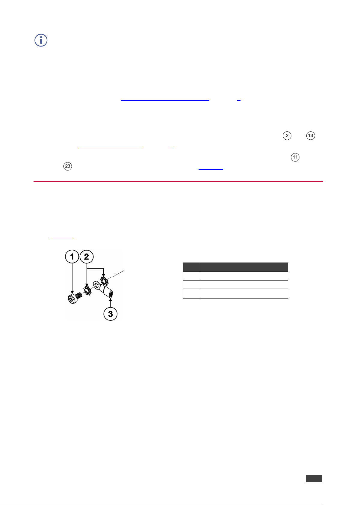
#
Component Description
1
M3X6 screw
2
1/8" Toothed Lock Washer
3
M3 Ring Tongue Terminal
transmitters close
in applications employing more than one transmitter, we
• CAT 5/6: use shielded CAT cable. (The connectors within the TP-752T/TP-752R ground
the shield).
• TERMINAL BLOCK: connect shielded cable, with the shield connected to the
ground tabs (see
• HD15: no special cautions need to be taken when connecting via standard VGA
Grounding the TP-752T/TP-752R on page 8).
cabling. (VGA cable is typically shielded and the connectors within the TP-
752T/TP-752R ground the shield).
4. Set the same baud rate on both devices via the BAUD RATE DIP-switches and
(see Setting the Baud Rate on page 9
).
5. Connect the power adapters to the TP-752T and TP-752R power connectors ( and
), and to the mains electricity (not shown in Figure 3
).
Grounding the TP-752T/TP-752R
You can use the grounding screw to earth the chassis of the unit to the building ground
preventing static electricity from impacting the performance of the unit.
:
Figure 4
defines the grounding screw components.
Figure 4: Grounding Connection Components
To ground the TP-752T/TP-752R, if required:
1. Connect the ring tongue terminal to the building grounding point wire (it is recommended
2
to use a green-yellow AWG#18 (0.82mm
) wire, crimped with a proper hand-tool).
2. Insert the M3x6 screw through the toothed lock washers and the tongue terminal in the
order shown above.
3. Insert the M3x6 screw (with the two toothed lock washers and ring tongue terminal) into
the grounding screw hole and tighten the screw.
Page 11

Kramer Electronics Ltd.
TP-752T / TP-752R – Connecting the TP-752T/TP-752R
9
Figure 5: Connecting to a Balanced Stereo Audio
Acceptor
Figure 6: Connecting to an Unbalanced Stereo Audio
Acceptor
If you are connecting to an RS
Tx to pin 2, Rx to pin 3, and G to pin 5.
DIP-switch 1
DIP-switch 2
DIP-switch 3
Baud Rate
OFF (up)
OFF (up)
OFF (up)
2400
ON (down)
OFF (up)
OFF (up)
4800
OFF (up)
ON (down)
OFF (up)
9600
ON (down)
ON (down)
OFF (up)
19200
OFF (up)
OFF (up)
ON (down)
28800
ON (down)
OFF (up)
ON (down)
38400
OFF (up)
ON (down)
ON (down)
57600
ON (down)
ON (down)
ON (down)
115200
Connecting the Output to a Balanced/Unbalanced
Stereo Audio Acceptor
The following are the pinouts for connecting the output to a balanced or unbalanced stereo
audio acceptor:
Connecting to TP-752T/TP-752R via RS-232
Passing bi-directional RS-232 signals between the devices, allows control of the display from
the source end and/or control of a source from the display end. For example, you can control
the Blu-ray player that is connected to TP-752T from the display side.
To connect a controller/device to be controlled via the RS-232 port:
• Connect the RS-232 9-pin D-sub port to the controller/controlled device.
-232 terminal block connector, connect only the following pins:
Setting the Baud Rate
A DIP-switch that is down is ON; a DIP-switch that is up is OFF.
To set the baud rate:
• Set the DIP-switches identically for TP-752T and TP-752R according to the table below:
Page 12
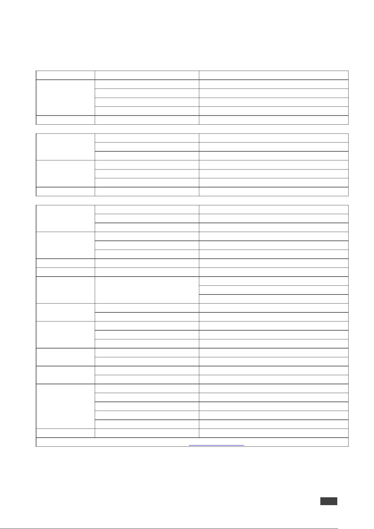
TP-752T / TP-752R – Technical Specifications
10
TP-752T
Inputs
1 HDMI
On a female HDMI connector
Outputs
1 LOOP HDMI
On a female HDMI connector
CAT 5/6
On an RJ-45 connector
VGA
On a 15-pin HD connector
2-wire
On a 2-pin terminal block connector
Ports
RS-232
On 9-pin D-sub connector for serial link extension
TP-752R
Inputs
CAT 5/6
On an RJ-45 connector
VGA
On a 15-pin HD connector
2-wire
On a 2-pin terminal block connector
Outputs
1 HDMI
On a female HDMI connector
1 S/PDIF
On an RCA connector
1 Balanced Stereo Audio
On a 5-pin terminal block connector
Ports
RS-232
On 9-pin D-sub connector for serial link extension
General
Video
Max Resolution
1080p60
Compliance
HDCP 1.4
Latency
0.35 seconds (typical)
Support
2.0 channel PCM, 48kHz/44.1kHz sampling rate
Bandwidth
12kHz
Analog THD + NOISE
0.08% @1kHz at nominal level
Extension Range
Full HD (1080p @60Hz)
Up to 600m (2000ft)
Extended RS-232
Baud Rate
2400 to 115200, selectable
Controls
Front Panel
ON LED indicator
Baud rate DIP-switches
Reset recessed button
Consumption
5V DC, 1.5A
Source
5.2V DC, 4A
Environmental
Operating Temperature
0° to +40°C (32° to 104°F)
Storage Temperature
-40° to +70°C (-40° to 158°F)
Humidity
10% to 90%, RHL non-condensing
Regulatory
Safety
CE, UL
Environmental
RoHs, WEEE
Enclosure
Size
Mega Tool
Cooling
Convection ventilation
General
Net Dimensions (W, D, H)
18.7cm x 11.5cm x 2.5cm (7.4" x 4.5" x 1")
Shipping Dimensions (W, D, H)
34.5cm x 16.5cm x 5.2cm (13.6" x 6.5" x 2.1")
Net Weight
0.46kg (1lbs) approx.
Shipping Weight
0.96kg (2.1lbs) approx.
Type
Aluminum
Accessories
Included
2 Power adapters, 2 power cords
Specifications are subject to change without notice at www.kramerav.com
Technical Specifications
Kramer Electronics Ltd.
Audio
Power
Conditions
Compliance
Information (per
device)
The terms HDMI, HDMI High-Definition Multimedia Interface, and the HDMI Log o are trademarks or regis tered trademarks of HDMI Licensing Administrator, I nc.
Page 13

The warranty obligations of Kramer Electronics Inc. (“Kramer Electronics”) for this product are limited to the terms set forth below:
What is Covered
This limited warranty covers defects in materials and workmanship in this product.
What is Not Covered
This limited warranty does not cover any damage, deterioration or malfunction resulting from any alteration, modification, improper or unreasonable use
or maintenance, misuse, abuse, accident, neglect, exposure to excess moisture, fire, improper packing and shipping (such claims must be presented to
the carrier), lightning, power surges, or other acts of nature. This limited warranty does not cover any damage, deterioration or malfunction resulting
from the installation or removal of this product from any installation, any unauthorized tampering with this product, any repairs attempted by anyone
unauthorized by Kramer Electronics to make such repairs, or any other cause which does not relate directly to a defect in materials and/or workmanship
of this product. This limited warranty does not cover cartons, equipment enclosures, cables or accessories used in conjunction with this product.
Without limiting any other exclusion herein, Kramer Electronics does not warrant that the product covered hereby, including, without limitation, the
technology and/or integrated circuit(s) included in the product, will not become obsolete or that such items are or will remain compatible with any other
product or technology with which the product may be used.
How Long this Coverage Lasts
The standard limited warranty for Kramer products is seven (7) years from the date of original purchase, with the following exceptions:
1. All Kramer VIA hardware products are covered by a standard three (3) year warranty for the VIA hardware and a standard three (3) year
warranty for firmware and software updates; all Kramer VIA accessories, adapters, tags, and dongles are covered by a standard one (1) year
warranty.
2. All Kramer fiber optic cables, adapter-size fiber optic extenders, pluggable optical modules, active cables, cable retractors, all ring mounted
adapters, all Kramer speakers and Kramer touch panels are covered by a standard one (1) year warranty.
3. All Kramer Cobra products, all Kramer Calibre products, all Kramer Minicom digital signage products, all HighSecLabs products, all
streaming, and all wireless products are covered by a standard three (3) year warranty.
4. All Sierra Video MultiViewers are covered by a standard five (5) year warranty.
5. Sierra switchers & control panels are covered by a standard seven (7) year warranty (excluding power supplies and fans that are covered for
three (3) years).
6. K-Touch software is covered by a standard one (1) year warranty for software updates.
7. All Kramer passive cables are covered by a ten (10) year warranty.
Who is Covered
Only the original purchaser of this product is covered under this limited warranty. This limited warranty is not transferable to subsequent purchasers or
owners of this product.
What Kramer Electronics Will Do
Kramer Electronics will, at its sole option, provide one of the following three remedies to whatever extent it shall deem necessary to satisfy a proper
claim under this limited warranty:
1. Elect to repair or facilitate the repair of any defective parts within a reasonable period of time, free of any charge for the necessary parts and
labor to complete the repair and restore this product to its proper operating condition. Kramer Electronics will also pay the shipping costs
necessary to return this product once the repair is complete.
2. Replace this product with a direct replacement or with a similar product deemed by Kramer Electronics to perform substantially the same
function as the original product.
3. Issue a refund of the original purchase price less depreciation to be determined based on the age of the product at the time remedy is sought
under this limited warranty.
What Kramer Electronics Will Not Do Under This Limited Warranty
If this product is returned to Kramer Electronics or the authorized dealer from which it was purchased or any other party authorized to repair Kramer
Electronics products, this product must be insured during shipment, with the insurance and shipping charges prepaid by you. If this product is returned
uninsured, you assume all risks of loss or damage during shipment. Kramer Electronics will not be responsible for any costs related to the removal or reinstallation of this product from or into any installation. Kramer Electronics will not be responsible for any costs related to any setting up this product, any
adjustment of user controls or any programming required for a specific installation of this product.
How to Obtain a Remedy Under This Limited Warranty
To obtain a remedy under this limited warranty, you must contact either the authorized Kramer Electronics reseller from whom you purchased this
product or the Kramer Electronics office nearest you. For a list of authorized Kramer Electronics resellers and/or Kramer Electronics authorized service
providers, visit our web site at www.kramerav.com or contact the Kramer Electronics office nearest you.
In order to pursue any remedy under this limited warranty, you must possess an original, dated receipt as proof of purchase from an authorized Kramer
Electronics reseller. If this product is returned under this limited warranty, a return authorization number, obtained from Kramer Electronics, will be
required (RMA number). You may also be directed to an authorized reseller or a person authorized by Kramer Electronics to repair the product.
If it is decided that this product should be returned directly to Kramer Electronics, this product should be properly packed, preferably in the original
carton, for shipping. Cartons not bearing a return authorization number will be refused.
Limitation of Liability
THE MAXIMUM LIABILITY OF KRAMER ELECTRONICS UNDER THIS LIMITED WARRANTY SHALL NOT EXCEED THE ACTUAL PURCHASE PRICE PAID
FOR THE PRODUCT. TO THE MAXIMUM EXTENT PERMITTED BY LAW, KRAMER ELECTRONICS IS NOT RESPONSIBLE FOR DIRECT, SPECIAL,
INCIDENTAL OR CONSEQUENTIAL DAMAGES RESULTING FROM ANY BREACH OF WARRANTY OR CONDITION, OR UNDER ANY OTHER LEGAL
THEORY.
the limitation of liability to specified amounts, so the above limitations or exclusions may not apply to you.
Some countries, districts or states do not allow the exclusion or limitation of relief, special, incidental, consequential or indirect damages, or
Exclusive Remedy
TO THE MAXIMUM EXTENT PERMITTED BY LAW, THIS LIMITED WARRANTY AND THE REMEDIES SET FORTH ABOVE ARE EXCLUSIVE AND IN LIEU OF
ALL OTHER WARRANTIES, REMEDIES AND CONDITIONS, WHETHER ORAL OR WRITTEN, EXPRESS OR IMPLIED. TO THE MAXIMUM EXTENT
PERMITTED BY LAW, KRAMER ELECTRONICS SPECIFICALLY DISCLAIMS ANY AND ALL IMPLIED WARRANTIES, INCLUDING, WITHOUT LIMITATION,
WARRANTIES OF MERCHANTABILITY AND FITNESS FOR A PARTICULAR PURPOSE. IF KRAMER ELECTRONICS CANNOT LAWFULLY DISCLAIM OR
EXCLUDE IMPLIED WARRANTIES UNDER APPLICABLE LAW, THEN ALL IMPLIED WARRANTIES COVERING THIS PRODUCT, INCLUDING WARRANTIES
OF MERCHANTABILITY AND FITNESS FOR A PARTICULAR PURPOSE, SHALL APPLY TO THIS PRODUCT AS PROVIDED UNDER APPLICABLE LAW.
IF ANY PRODUCT TO WHICH THIS LIMITED WARRANTY APPLIES IS A “CONSUMER PRODUCT” UNDER THE MAGNUSON-MOSS WARRANTY ACT (15
U.S.C.A. §2301, ET SEQ.) OR OTHER APPLICABLE LAW, THE FOREGOING DISCLAIMER OF IMPLIED WARRANTIES SHALL NOT APPLY TO YOU, AND
ALL IMPLIED WARRANTIES ON THIS PRODUCT, INCLUDING WARRANTIES OF MERCHANTABILITY AND FITNESS FOR THE PARTICULAR PURPOSE,
SHALL APPLY AS PROVIDED UNDER APPLICABLE LAW.
Other Conditions
This limited warranty gives you specific legal rights, and you may have other rights which vary from country to country or state to state.
This limited warranty is void if (i) the label bearing the serial number of this product has been removed or defaced, (ii) the product is not distributed by
Kramer Electronics or (iii) this product is not purchased from an authorized Kramer Electronics reseller. If you are unsure whether a reseller is an
authorized Kramer Electronics reseller, visit our web site at www.kramerav.com or contact a Kramer Electronics office from the list at the end of this
document.
Your rights under this limited warranty are not diminished if you do not complete and return the product registration form or complete and submit the
online product registration form. Kramer Electronics thanks you for purchasing a Kramer Electronics product. We hope it will give you years of
satisfaction.
Page 14

2900-301041
1
SAFETY WARNING
Disconnect the unit from the power supply before opening and servicing
For the latest information on our products and a list of Kramer distributors, visit our Web site where
updates to this user manual may be found.
P/N:
Rev:
We welcome your questions, comments, and feedback.
www.KramerAV.com
info@KramerAV.com
 Loading...