

Page 1
TP-752T/TP-752R Quick Start
P/N:
2900- 3 0 1 0 4 1 QS
Rev:
5
TP-752R
Power adapter
Bracket set
Quick start guide
Rubber feet
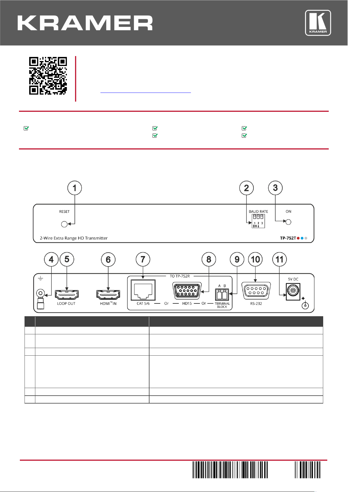
1
RESET Recessed Button
Press to reset the device.
be identical).
3
ON LED
Lights green when the device is powered.
4
Ring Tongue Terminal Ground Screw
Use to shield the cable between the transmitter and the receiver, for
highly recommended to use shielded cable.
5
LOOP OUT HDMI Connector
Connect to a local monitor.
6
HDMITM IN Connector
Connect to an HDMI source.
TP-752T/TP-752R Quick Start Guide
This guide helps you install and use your TP-752T/TP-752R for the first time.
Scan for full manual
Go to www.kramerav.com/downloads/TP-752T
upgrades are available.
Step 1: Check what’s in the box
TP-752T 2-Wire Extra Range HD Transmitter /
2-Wire Extra Range HD Receiver
Step 2: Get to know your TP-752T/TP-752R
TP-752T 2-Wire Extra Range HD Transmitter
to download the latest user manual and check if firmware
# Feature Function
2 BAUD RATE DIP-switches Set the RS-232 baud rate (baud rate on TP-752T and TP-752R should
example, when using coax cabling or 2-wire shielded cabling connected
to the terminal block connector.
Note that for multiple TP-752T / TP-752R systems in close proximity, it is
Page 2
7
TO TP-752R
CAT 5/6 RJ-45 Port
Connect to the RJ-45 port on TP-752R.
8
HD15 15-pin HD Connector
Connect to the 15-pin HD connector on TP-752R.
9
Connect to the 2-pin terminal block connectors on TP-752R.
ground tab (the ring tongue terminal grounding screw).
display from the source end/control of a source from the display end.
11
5V DC
+5V DC connector for powering the unit.
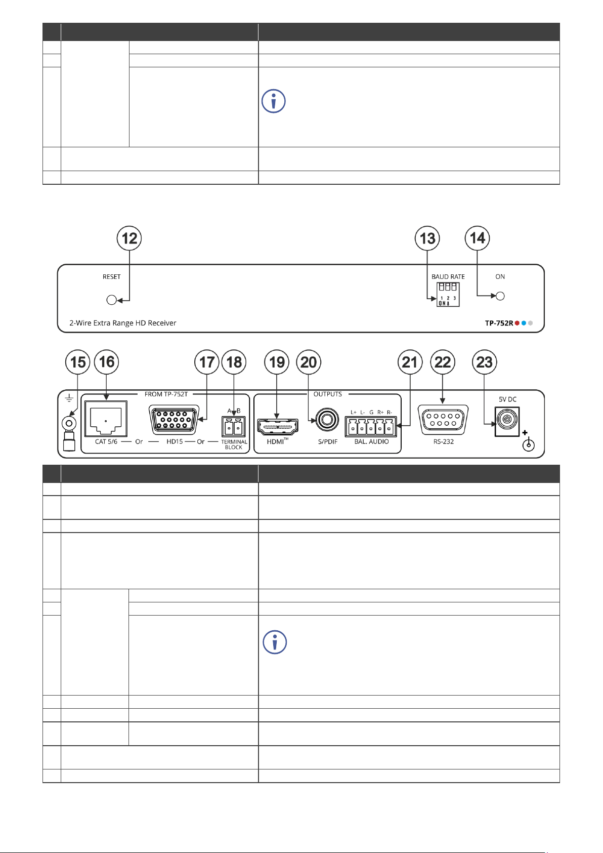
12
RESET Recessed Button
Press to reset the device.
13
BAUD RATE DIP-switches
Set the baud rate (baud rate on TP-752T and TP-752R should be
identical).
14
ON LED
Lights green when the device is powered.
15
Ring Tongue Terminal Ground Screw
Use to shield the cable between the transmitter and the receiver, for
highly recommended to use shielded cable.
16
FROM
CAT 5/6 RJ-45 Port
Connect to the RJ-45 port on TP-752T.
17
HD15 15-pin HD Connector
Connect to the 15-pin HD connector on TP-752T.
18
A, B 2-pinTERMINAL BLOCK
Connect to the 2-pin terminal block connectors on TP-752T.
For 2-wire cabling where the 2 wires have similar
ground tab (the ring tongue terminal grounding screw).
19
OUTPUTS
HDMI Connector
Connect to an HDMI acceptor.
20 S/PDIF RCA Connector
Connect to a digital audio acceptor.
21 BAL. AUDIO 5-pin Terminal
Block Connector
Connect to a stereo balanced audio acceptor.
display from the source end/control of a source from the display end.
23
5V DC
+5V DC connector for powering the unit.
# Feature Function
(Connect via
one of these
options)
A, B 2-pin TERMINAL BLOCK
Connector
For 2-wire cabling where the 2 wires have similar
characteristics (e.g. twin-flex cable), wire by connecting to the
2 terminals of the terminal block connector.
When using co-ax cable, it is best to wire with the inner cable
connected to the A terminal, and the shield connected to the
10 RS-232 9-pin D-sub Connector Bi-directional RS-232 between the devices, allowing control of the
TP-752R 2-Wire Extra Range HD Receiver
# Feature Function
example, when using coax cabling or 2-wire shielded cabling connected
to the terminal block connector.
Note that for multiple TP-752T / TP-752R systems in close proximity, it is
TP-752T
(Connect via
one of these
options)
Connector
characteristics (e.g. twin-flex cable), wire by connecting to the
2 terminals of the terminal block connector.
When using co-ax cable, it is best to wire with the inner cable
connected to the A terminal, and the shield connected to the
22 RS-232 9-pin D-sub Connector
Bi-directional RS-232 between the devices, allowing control of the
Page 3

Install TP-752T / TP-752R using one of the following methods:
Because of the extremely high sensitivity of the receivers, there may be crosstalk between systems within
Safety Instructions (See www.kramerav.com for updated safety information)
Caution:
Warning
• Disconnect the power and unplug the unit from the wall before installing.
DIP-switch 1
DIP-switch 2
DIP-switch 3
Baud Rate
OFF (up)
OFF (up)
OFF (up)
2400
ON (down)
OFF (up)
OFF (up)
4800
OFF (up)
ON (down)
OFF (up)
9600
ON (down)
ON (down)
OFF (up)
19200
OFF (up)
OFF (up)
ON (down)
28800
ON (down)
OFF (up)
ON (down)
38400
OFF (up)
ON (down)
ON (down)
57600
ON (down)
ON (down)
ON (down)
115200
Step 3: Install TP-752T/TP-752R
• Attach the rubber feet and place the unit on a flat surface.
• Fasten a bracket (included) on each side of the unit and attach it to a flat surface.
For more information go to www.kramerav.com/downloads/TP-752T
.
• Mount the unit in a rack using the recommended rack adapter (see
www.kramerav.com/product/TP-752T
).
Step 4: Connect the inputs and outputs
Always switch OFF the power on each device before connecting it to your TP-752T/TP-752R devices. For best results, we
recommend that you always use Kramer high-performance cables to connect AV equipment to TP-752T/TP-752R.
close proximity, and when running cabling from multiple transmitters close together. To prevent this, in
applications employing more than one transmitter, we recommend using shielded cabling with the shield
grounded. When connecting via:
• CAT 5/6: use shielded CAT cable. (The connectors within the TP-752T/TP-752R ground the shield).
• TERMINAL BLOCK: connect shielded cable, with the shield connected to the ground tab(s).
• HD15: no special cautions need to be taken when connecting via standard VGA cabling. (VGA cable is
typically shielded,
and the connectors within the TP-752T/TP-752R ground the shield).
Step 5: Connect the power
Connect the power cord to TP-752T and plug it into the mains electricity.
• For products with relay terminals and GPI\O ports, please refer to the permitted rating for an external connection, located next to the terminal or in the User Manual.
• There are no operator serviceable parts inside the unit.
:
• Use only the power cord that is supplied with the unit.
Step 6: Operate TP-752T/TP-752R
Baud Rate DIP-switch Setup:
A switch that is down is on; a switch that is up is off. By default, all the switches are down (ON).
Page 4

Technical Specifications
TP-752T
Inputs
1 HDMI
On a female HDMI connector
Outputs
1 LOOP HDMI
On a female HDMI connector
CAT 5/6
On an RJ-45 connector
VGA
On a 15-pin HD connector
2-wire
On a 2-pin terminal block connector
Ports
RS-232
On 9-pin D-sub connector for serial link extension
TP-752R
Inputs
CAT 5/6
On an RJ-45 connector
VGA
On a 15-pin HD connector
2-wire
On a 2-pin terminal block connector
Outputs
1 HDMI
On a female HDMI connector
1 S/PDIF
On an RCA connector
1 Balanced Stereo Audio
On a 5-pin terminal block connector
Ports
RS-232
On 9-pin D-sub connector for serial link extension
General
Video
Max Resolution
1080p60
Compliance
HDCP 1.4
Latency
0.35 seconds (typical)
Audio
Support
2.0 channel PCM, 48kHz/44.1kHz sampling rate
Bandwidth
12kHz
Analog THD + NOISE
0.08% @1kHz at nominal level
Extension Range
Full HD (1080p @60Hz)
Up to 600m (2000ft)
Extended RS-232
Baud Rate
2400 to 115200, selectable
Controls
Front Panel
ON LED indicator
Baud rate DIP-switches
Reset recessed button
Power
Consumption
5V DC, 1.5A
Source
5.2V DC, 4A
Environmental
Operating Temperature
0° to +40°C (32° to 104°F)
Storage Temperature
-40° to +70°C (-40° to 158°F)
Humidity
10% to 90%, RHL non-condensing
Regulatory
Safety
CE, UL
Environmental
RoHs, WEEE
Enclosure
Size
Mega Tool
Cooling
Convection ventilation
Net Dimensions (W, D, H)
18.75cm x 11.5cm x 2.54cm (7.4" x 4.5" x 1")
Shipping Dimensions (W, D, H)
34.5cm x 16.5cm x 5.2cm (13.6" x 6.5" x 2.1")
Net Weight
0.46kg (1lbs) approx.
Shipping Weight
0.96kg (2.1lbs) approx.
Type
Aluminum
Accessories
Included
2 Power adapters, 2 power cords
Specifications are subject to change without notice at www.kramerav.com
Conditions
Compliance
General Information
(per device)
The terms HDMI, HDMI High-Definition Multimedia Interface, and the HDMI Log o are trademarks or regis tered trademarks of HDMI Licensing Administrator, I nc.
 Loading...