

Page 1
TP-594Txr / TP-594Rxr Quick Start
P/N:
2900- 301015QS
Rev:
2
Scan for full manual
TP-594Txr/TP-594Rxr Quick Start Guide
This guide helps you install and use your TP-594Txr/TP-594Rxr for the first time.
Go to www.kramerav.com/downloads/TP-594Txr, TP-594Rxr to download the latest user manual and check
if firmware upgrades are available.
Step 1: Check what’s in the box
TP-594Txr HDMI Line Transmitter or
1 48V DC power adapter and cord for TP-594Txr or
1 Bracket set
TP-594Rxr HDMI Line Receiver
1 12V DC power adapter and cord for TP-594Rxr
4 Rubber feet
1 Quick start guide
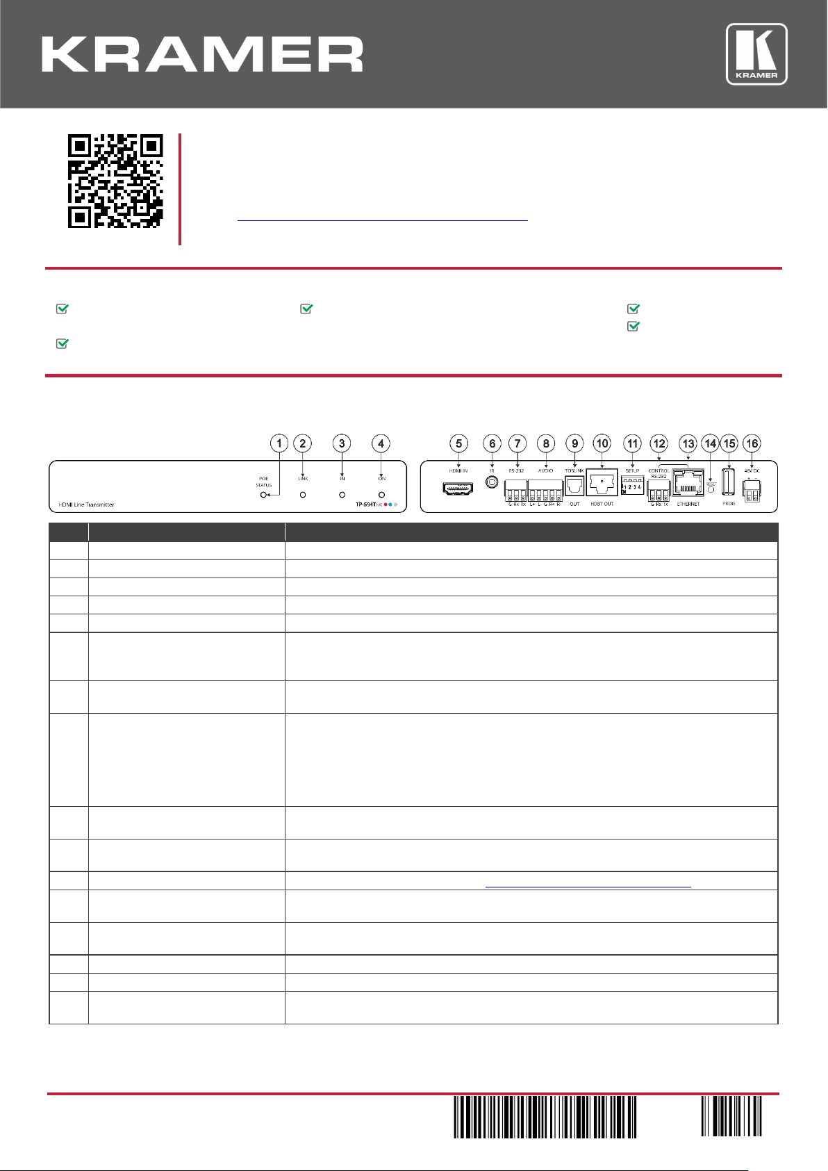
Step 2: Get to know your TP-594Txr / TP-594Rxr
TP-594Txr
#
Feature
Function
1
POE STATUS LED
Lights green when power is provided over the HDBT connection.
2
LINK LED
Lights green when the HDBT link is valid.
3
IN LED
Lights green when an active source device input signal is detected.
4
ON LED
Lights green when the device receives power.
5
HDMI™ IN Connector
Connect to an HDMI source.
6
IR 3.5mm Mini Jack Connector
Connect to an external IR emitter to control a local device from the receiver (TP-594Rxr)
side.
Connect to an IR sensor to control a remote device connected to the TP-594Rxr receiver.
7
RS-232 3-pin Terminal Block
Connector
Connect to a controller device (for example, SL-240C ) to control a remote device via serial
controller (for example, the HDMI OUT acceptor) that is connected to TP-594Rxr.
8
AUDIO 5-pin Terminal Block
Connector
Connect to either a stereo balanced audio source or acceptor (the connection type is
defined via the embedded web pages):
Connect an audio source to extend an audio signal from TP-594Txr to the audio acceptor
on the receiver side via the HDBT line.
Connect an audio acceptor to output the audio signal received from the audio source on
TP-594Rxr via the HDBT line.
9
TOSLINK OUT Connector
Digital audio on a TOSLINK optical female connector, for outputting the digital audio signal
that is extended from the receiver to an audio acceptor.
10
HDBT OUT Connector
Connect to the RJ-45 HDBT IN connector on a receiver (for example, TP-594Rxr or
TP-590Rxr) to extend the signals between the TP-594Txr and the receiver.
11
SETUP 4-way DIP-switches
Set the operation DIP-switches (see Step 4: Connect the inputs and outputs).
12
CONTROL RS-232 3-pin Terminal
Block Connector
Connect to a PC to control the device.
13
CONTROL ETHERNET RJ-45
Connector
Connect to a PC to control the device or for LAN extension.
14
RESET Recessed Button
Press and hold to reset settings to factory default values.
15
PROG USB Port
Connect to a USB memory device to upgrade the firmware.
16
48V DC Power Terminal Block
Connector
Connect to the supplied power adapter.
The terms HDMI, HDMI High-Definition Multimedia Interface, and the HDMI Logo are trademarks or registered trademarks of HDMI Licensing Administrator, Inc.
Page 2
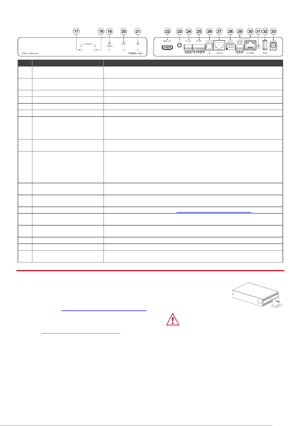
TP-594Rxr
#
Feature
Function
17
GATEWAY Tx LED
Lights blue to indicate gateway activity of any RS-232, IR or CEC signals sent, as selected
in the embedded web pages.
18
GATEWAY Rx LED
Lights blue to indicate gateway activity of any RS-232, IR or CEC signals received, as
selected in the embedded web pages.
19
POE STATUS LED
Lights green when power is received over the TP connection.
20
LINK LED
Lights green when the HDBT link is valid.
21
ON LED
Lights green when the device receives power.
22
HDMI OUT Connector
Connect to an HDMI acceptor.
23
IR 3.5mm Mini Jack Connector
Connect to an external IR emitter to control a local device from the transmitter (TP-594Txr)
side.
Connect to an IR sensor to control a remote device connected to the TP-594Txr
transmitter.
24
RS-232 3-pin Terminal Block
Connector
Connect to an RS-232 device to be controlled, for example, a projector.
25
AUDIO 5-pin Terminal Block
Connector
Connect to a stereo balanced audio source or an acceptor (the connection type is defined
via the embedded web pages):
Connect an audio acceptor to output the audio signal received from the audio source on
the transmitter side via the HDBT line.
Connect an audio source to extend an audio signal from TP-594Rxr to the audio acceptor
on the TP-594Txr via the HDBT line.
26
TOSLINK IN Connector
1 digital audio on a TOSLINK optical female connector for digital audio input and extension
to the transmitter.
27
HDBT IN Connector
Connect to the RJ-45 HDBT OUT connector on a transmitter (for example,
TP-594Txr or TP-590Txr) to extend the signals between TP-594Rxr and the transmitter.
28
SETUP 4-way DIP-switches
Set the operation DIP-switches (see Step 4: Connect the inputs and outputs).
29
CONTROL RS-232 3-pin Terminal
Block Connector
Connect to a PC to control the device.
30
CONTROL ETHERNET RJ-45
Connector
Connect to a PC to control the device or for LAN extension.
31
RESET Recessed Button
Press and hold to reset settings to factory default values.
32
PROG USB Port
Connect to a USB memory device to upgrade the firmware.
33
12V DC Power Connector
12V DC connector for powering the unit when unit is not powered via the HDBT link by the
transmitter.
Step 3: Mount TP-594Txr/TP-594Rxr
Install TP-594Txr/TP-594Rxr using one of the following methods:
• Attach the rubber feet and place the unit on a flat surface.
• Fasten a bracket (included) on each side of the unit and attach it to a flat
surface (see www.kramerav.com/downloads/TP-594Txr.).
• Mount the unit in a rack using the recommended
rack adapter
(see www.kramerav.com/product/TP-594Txr).
• Ensure that the environment (e.g., maximum ambient temperature &
air flow) is compatible for the device.
• Avoid uneven mechanical loading.
• Appropriate consideration of equipment nameplate ratings should be
used for avoiding overloading of the circuits.
• Reliable earthing of rack-mounted equipment should be maintained.
Page 3

Step 4: Connect the inputs and outputs
Always switch OFF the power on each device before connecting it to your TP-594Txr/TP-594Rxr. For best results, we
recommend that you always use Kramer high-performance cables to connect AV equipment to TP-594Txr/TP-594Rxr.
Wiring the RJ-45 Connectors
DIP-Switch Settings
For the HDBT connector, see the wiring diagram
below. It is recommended that the cable ground
shielding be connected/soldered to the
connector shield
All DIP-switches are set to OFF (up) by default except DIPswitch 1 which is set to ON by default.
PIN EIA /TIA 568B
PIN
Wire Color
# Feature
Dip-switch Settings
1
Orange / White
1 Range
Mode
OFF (up) – HDBaseT ultra-long range (provides increased
range at a reduced bandwidth).
ON (down) – Normal range.
2
Orange
3
Green / White
4
Blue
The ultra-long range mode is activated when DIPswitch 1 on at least one of the devices is set to ON.
5
Blue / White
6
Green
7
Brown / White
2 Define IR
Passthrough
OFF (up) – Pass-through the IR signal to the IR port via IR
cable.
ON (down) – Add IR modulation to the IR output signal
(applies only when the IR port is connected to an IR emitter
cable).
8
Brown
The IR Pass-through DIP-switch setup depends on
the IR control configuration. We recommend that
you test which position best suits your application.
3 EDID Lock
Off – EDID is acquired automatically.
On – EDID locks the current EDID so that changes on the
output do not result in changes to the EDID.
For optimum range and performance use the
recommended Kramer cables available at
www.kramerav.com/product/TP-594T,TP-594R.
EDID remains locked to auto-EDID changes when
replacing the display device, for example, and does
not apply to manual EDID changes such as EDID
Designer EDID setup and EDID changes due to
panel keys/switches user changes.
4
N/A
For future use.
Step 5: Connect the power
Connect the 48V DC power supply to TP-594Txr and the 12V DC power supply to the TP-594Rxr and plug both into the
mains electricity.
When TP-594Txr is used as a PoE provider for the TP-594Rxr, you do not need to connect the 12V DC power supply to the
TP-594Rxr unless power supply redundancy is needed.
Safety Instructions
Caution:
There are no operator serviceable parts inside the unit.
Warning:
Use only the Kramer Electronics power adapter that is provided with the unit.
Warning:
Disconnect the power and unplug the unit from the wall before installing.
See www.KramerAV.com for updated safety information.
Page 4

Step 6: Operate TP-594Txr/TP-594Rxr
Operate TP-594Txr/TP-594Rxr via:
• Remotely, by RS-232
serial commands
transmitted by a touch
screen system, PC, or
other serial controller.
• Embedded web pages
via the Ethernet.
RS-232 Control / Protocol 3000
Baud Rate:
115,200
Parity:
None
Data Bits:
8
Command Format:
ASCII
Stop Bits:
1
Example (pass embedded audio to the output): #AUD-EMB 1,2,0<CR>
Default Ethernet Parameters
IP Address:
DHCP enabled
Fallback IP Address:
TP-594Txr: 192.168.1.39; TP-594Rxr 192.168.1.40
Fallback Subnet Mask:
255.255.255.0
TCP Port #:
5000
Fallback:
192.168.1.1
UDP Port #:
50000
Technical Specifications
TP-594Txr
Input
HDMI
On a female HDMI connector
Output
HDBT
On an RJ-45 connector
Optical (Digital Audio)
On a TOSLINK® connector
Input/Output (configurable)
Balanced Stereo Audio
On a 5-pin terminal block connector
TP-594Rxr
Input
HDBT
On an RJ-45 connector
Optical (Digital Audio)
On a TOSLINK® connector
Output
HDMI
On a female HDMI connector
Input/Output (configurable)
Balanced Stereo Audio
On a 5-pin terminal block connector
General
Ports
Ethernet
On an RJ-45 female connector for device control and LAN extension
RS-232
On a 3-pin terminal block for serial link extension
IR
On a 3.5mm mini jack for IR extension
Control RS-232
On a 3-pin terminal block for device control
USB
On a female USB-A connector for device firmware upgrade
Extension
We recommend that you use Kramer shielded cables to achieve optimum extension ranges
Compression
Low-level standard DSC compression for signals above 4K@60 (4:2:0)
4K@60 (4:4:4) Range
Compression: up to 100m (330ft)
4K@60 (4:2:0) Range
No compression: up to 100m (330ft)
Full HD (1080p@60Hz) Range
No compression: up to 130m (430ft)
Ultra-long mode: up to 180m (590ft)
Compliance
HDBaseT 2.0
Video
Max Bandwidth
Compression: 17.95Gbps (5.98Gbps per graphic channel)
No compression: 10.2Gbps (3.4Gbps per graphic channel)
Max Resolution
Compression: 3840x2160@60Hz 4:4:4 24bpp
No compression: 4096x2160@60Hz 4:2:0 24bpp
Compliance
HDMI 2.0, HDCP 2.2, HDR 10
Controls
Front Panel
IN (TP-594Txr only), GATEWAY Tx/Rx (TP-594Rxr only), POE STATUS,
LINK and ON LED indicators
Rear Panel
DIP-switches
Extended RS-232
Baud Rate
300 to 115200baud
Extended Ethernet
Data Rate
Up to 100Mbps
Extended IR
Frequency
20kHz to 100kHz
Power
Consumption
TP-594Txr + TP-594Rxr: 48V DC, 0.65A
TP-594Txr: 48V DC, 0.45A
TP-594Rxr: 12V DC, 1.1A
Source
TP-594Txr: 48V DC, 1.36A
TP-594Rxr: 12V DC, 2A
Environmental Conditions
Operating Temperature
0° to +40°C (32° to 104°F)
Storage Temperature
-40° to +70°C (-40° to 158°F)
Humidity
10% to 90%, RHL non-condensing
Regulatory Compliance
Safety
CE, UL
Environmental
RoHs, WEEE
Enclosure
Size
Tool
Type
Aluminum
Cooling
Convection ventilation
General
Net Dimensions (W, D, H), each
18.7cm x 11.5cm x 2.5cm (7.4" x 4.5" x 1")
Shipping Dimensions (W, D, H)
34.5cm x 16.5cm x 5.2 cm (13.6" x 6.5" x 2")
Net Weight, each
0.4kg (0.9bs) approx.
Shipping Weight
0.95kg (2.1lbs) approx.
Accessories
Included
1 power adapter, 1 power cord and 1 bracket set per device
Specifications are subject to change without notice at www.kramerav.com
 Loading...