

Page 1
TP
(P/N: 2900
2900- 3 0 0 8 6 8 QS
1
TP-580TD, TP-580RD
1 Power adapter and cord
1 Quick start guide
1
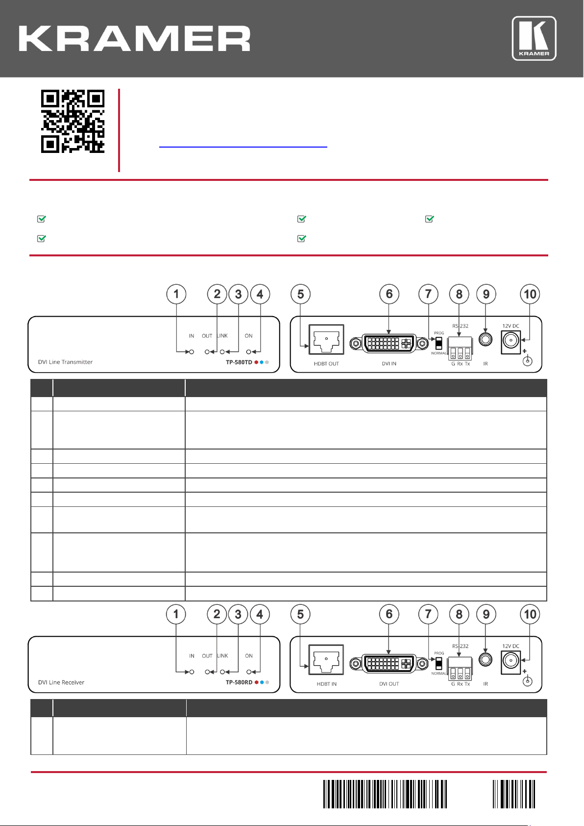
IN LED
Lights green when an active DVI source device input signal is detected.
that is connected to this output).
5
HDBT IN RJ-45 Connector
Connect to the RJ-45 OUT connector on a receiver (for example, TP-580RD).
6
DVI IN Connector
Connect to a DVI source.
TP-580RD
9
IR 3.5mm Mini Jack Connector
Connect to an external infrared emitter / sensor.
10
12V DC Power Connector
12V DC connector for powering the unit.
TP-580TD, TP-580RD Quick Start Guide
This guide helps you install and use your TP-580TD, TP-580RD for the first time.
to download the latest user manual and check if
Scan for full manual
Go to www.kramerav.com/downloads/TP-580TD
firmware upgrades are available.
Step 1: Check what’s in the box
HDMI Line Transmitter / Receiver 4 Rubber feet 1 Bracket set
Step 2: Get to know your TP-580TD, TP-580RD
# Feature Function
2 OUT LED Lights green when an active, far-end sink (acceptor) DVI output signal is detected via the
HDBaseT link (a DVI signal is detected from a sink device connected to the HDBaseT receiver
3 LINK LED Lights green when an HDBT link is established with the HDBaseT receiver.
4 ON LED Lights green when the device receives power.
7 PROG/NORMAL Switch Slide to PROG to upgrade to the latest Kramer firmware via RS-232, or slide to NORMAL for
normal operation.
8 RS-232 3-pin Terminal Block
Connector
# Feature Function
1 IN LED Lights green when an active far-end source DVI input signal is detected via the HDBaseT link
Connect to a laptop to control TP-580TD or perform firmware upgrade.
Connect to a controller device (for example, SL-240C) to serially control a remote device (for
example, the DVI OUT acceptor) that is connected to
(a DVI signal is detected from a source device connected to the HDBaseT transmitter that is
connected to this input).
.
-580TD, TP-580RD Quick Start
-300868QS REV 1)
P/N:
Rev:
Page 2
2
OUT LED
Lights green when an HDMI output device is detected.
3
LINK LED
Lights green when an HDBT link is established with the HDBaseT transmitter.
TP-580TD
6
DVI OUT Connector
Connect to a DVI acceptor.
normal operation.
serial controller (for example, SL-240C) that is connected to TP-580TD.
10
12V DC Power Connector
12V DC connector for powering the unit.
Caution:
There are no operator serviceable parts inside the unit
Warning:
Use only the Kramer Electronics power supply that is provided with the unit
Warning:
Disconnect the power and unplug the unit from the wall before installing
See www.KramerAV.com for updated safety information.
# Feature Function
4 ON LED Lights green when the device receives power.
5 HDBT IN RJ-45 Connector Connect to the RJ-45 OUT connector on a transmitter (for example,
).
7 PROG/NORMAL Switch Slide to PROG to upgrade to the latest Kramer firmware via RS-232, or slide to NORMAL for
8 RS-232 3-pin Terminal Block
Connector
Connect to a laptop to control TP-580RD or perform firmware upgrade.
Connect to a controlled device (for example, the DVI OUT acceptor) to control it from a remote
9 IR 3.5mm Mini Jack Connector Connect to an external infrared emitter / sensor.
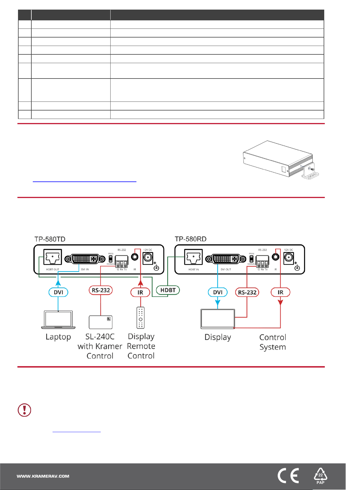
Step 3: Install the TP-580TD, TP-580RD
Install TP-580TD, TP-580RD using one of the following methods:
• Attach the rubber feet and place the unit on a flat surface.
• Fasten a bracket (included) on each side of the unit and attach it to a flat surface.
For more information go to
www.kramerav.com/downloads/TP-580TD.
• Mount the unit in a rack using an optional RK-3T rack adapter.
Step 4: Connect the inputs and outputs
Always switch OFF the power on each device before connecting it to your TP-580TD, TP-580RD. For best results, we recommend
that you always use Kramer high-performance cables to connect AV equipment to the TP-580TD, TP-580RD.
Step 5: Connect the power
Connect the power adapter to the TP-580TD, TP-580RD and plug the adapter into the mains electricity.
Safety Instructions
 Loading...