

Page 1

Kramer Electronics, Ltd.
USER MANUAL
Model:
SG-6006
Genlock Multistandard SPG / SDI / AUDIO Generator
Page 2

Contents
i
Contents
1 Introduction 1
2 Getting Started 1
2.1 Quick Start 1
3 Overview 3
3.1 Recommendations for Best Performance 3
4 Defining the SG-6006 Genlock Multistandard SPG/SDI/Audio Generator 3
5 Installing the SG-6006 in a Rack 6
6 Connecting the SG-6006 7
7 Using the SG-6006 8
7.1 Operating the SG-6006 8
7.2 Locking the Front Panel 10
7.3 Remotely Operating the SG-6006 via RS-232 10
8 Technical Specifications 11
Figures
Figure 1: SG-6006 Front and Rear Panels 4
Figure 2 : Connecting the SG-6006 Genlock Multistandard SPG/SDI/Audio Generator
7
Figure 3: Connecting a PC without using a Null-modem Adapter
11
Tables
Table 1: SG-6006 Front and Rear Panel Features 5
Table 2: The SG-6006 Menu
9
Table 3: Technical Specifications of the SG-6006
11
Page 3

Introduction
1
1 Introduction
Welcome to Kramer Electronics! Since 1981, Kramer Electronics has been
providing a world of unique, creative, and affordable solutions to the vast range of
problems that confront the video, audio, presentation, and broadcasting
professional on a daily basis. In recent years, we have redesigned and upgraded
most of o ur line, ma king the best eve n better! Our 1,000-plus different models now
appear in 11 groups
1
Congratulations on purchasing your Kramer SG-6006 Genlock Multistandard
SPG
that are clearly defined by function.
2
• Studio master genlock for one stable source
/SDI/Audi o G e nerator which is ideal for:
• Black or color bar reference for professional video cameras that need a stable
reference
• Use as a test and alignment tool for professional video/audio equipment
• Use as a color bar generator as filler for re c ording in a duplication studio
Each package includes the following items:
• SG-6006 Genlock Multist andard SPG / SDI/Audio Ge nerator
• Power cord, rack “ears” and Null-modem adapter
• Windows
®
-based Kramer control software
3
• This user manual
4
2 Getting Started
We recommend that you:
• Unpack t he equip ment carefully and s ave the original box and packaging
materials for possible fut ure shipment
• Review the contents of this user manual
• Use Kramer high performance high resolution cables
5
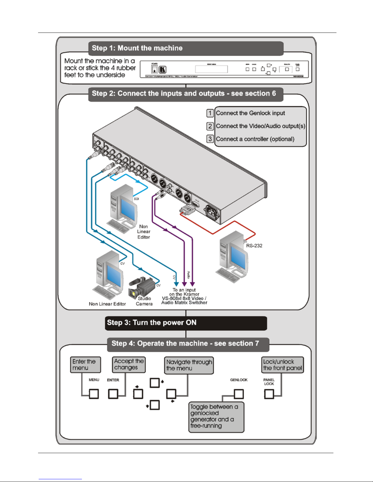
2.1 Quick Start
This quick start chart summarizes the basic setup and operation steps.
1 GROUP 1: Distribution Amplifiers; GROUP 2: Switchers and Matrix Switchers; GROUP 3: Control Systems; GROUP 4:
Format/Standards Converters; GROUP 5: Range Extenders and Repeaters; GROUP 6: Specialty AV Products; GROUP 7: Scan
Converters and Scalers; GROUP 8: Cables and Connectors; GROUP 9: Room Connectivity; GROUP 10: Accessories and Rack
Adapters; GROUP 11: Sierra Products
2 Sync Pulse Generator
3 Downloadable from
http://www.kramerelectronics.com
4 Download up-to-date Kramer user manuals from
http://www.kramerelectronics.com
5 The complete list of Kramer cables is available from
http://www.kramerelectronics.com
Page 4
Getting Started
KRAMER: SIMPLE CREATIVE TECHNOLOGY
2
Page 5

Overview
3
3 Overview
The SG-6006 is a broad c a st qualit y, multi-standard SPG (Sync Pulse Generator)
with black burst, color bar, and audio tone outputs. It has eight composite video
and four SDI outputs on BNC connectors. The analog video outputs—and the four
SDI outputs—can be configured as either a black burst or a color bar signal.
In particular, the SG-6006:
• Has audio outputs available in AES 75Ω (AES-3id) and AES-EBU digital
formats, as well as in unbalanced and balanced analog audio formats
• Has balanced audio and AES/EBU output s on XLR connectors, AES 75Ω
(AES-3id), SDI and composite video outputs on BNC connectors, and
unbalanced audio outputs on RCA connectors. All outputs are available
simultaneously
• Offers a choice of nine color bars (for video outputs), and you can set the
timing parameters, SCH and phase
• Features adjustme n ts fo r t he freque ncy and amplitude
• Features various options for SDI audio embedding
• Can be genlocked to an external composite video source via its looping input
with selectable termination
The SG-6006 is housed in a 19” 1U rack mountable enclosure, and is fed from a
100-240 VAC universal switching power supply.
The SG-6006 can be operated via the front pa nel buttons with an LCD and a userfriendly menu, and remotely operated via the RS-232 interface
1
3.1 Recommendations for Best Perfor m ance
.
To achieve the best performance:
• Connect only good quality connection cables, thus avoiding interference,
deterioration in signal q uality due to poor matching, and elevated noise levels
(often associated with lo w quality cables)
• Avoid interference from neighboring electrical appliances that may adversely
influence signal qualit y and posit ion your SG-6006 away from moisture,
excessive sunlight and dust
4 Defining the SG-6006 Genlock Multistandard SPG/SDI/Audio
Generator
Figure 1 and Table 1 define the front and rear panels of the SG-6006.
1 The Communication Protocol is available on request from Kramer support
Page 6

Defining the SG-6006 Genlock Multistandard SPG/SDI/Audio Generator
KRAMER: SIMPLE CREATIVE TECHNOLOGY
4
Figure 1: SG-6006 Front and Rear Panels
Page 7

Defining the SG-6006 Genlock Multistandard SPG/SDI/Audio Generator
5
Table 1: SG-6006 Front and Rear Panel Features
#
Feature
Function
1 POWER Switch Illuminated swi tch for tur ning the un it ON or OFF
2 SETUP / MENU
LCD Display
Displays user interface messages and configura tion menu
items
3 MENU Button Press to open the menu (see Section 7.14 )
ENTER Button Press to load and save a set up, and enter th e sub menus
5 Button Press to decrease numerical values or select from several
definitions
6 Button Press to move down the menu list
7 Button Press to move up the menu list
8 Button Press to increase numerical values or select from several
definitions
9 GENLOCK Button Press to togg le betw een a genlo c ked gener ato r a nd a f ree-
running generator
1
When lit, the machine will “ge nloc k” to a va lid refe ren ce inp ut .
When not lit, the timing of the generator is i nterna l ly gen erat ed
(free-running)
10 PANEL LOCK Button Press and hold
2
11
to lock/unlock the front panel buttons
REFERENCE
INPUT BNC
Connector
Connect a referen ce input fo r g en locking the mach ine
12 LOOP BNC
Connector
Connect to an ad di tiona l machine t o loop the ge nloc king
source
13 TERM Button When looping, r elease t he TERM but ton
When not loopin g, termin ate the l ine by pre ssing t he b utton
14 ANALOG VIDEO OUTPUT BNC
Connectors
Connect to the composite video acceptors (from 1 to 8)
15 SDI OUTPUT BNC Connectors Conne ct t o the SDI accep tors (from 1 to 4)
16
AUDIO
OUTPUTS
AES 75
Ω
3
1+2
BNC
Connectors
Connect to an AES-3id d ig ital aud io ac ceptor (f or chan ne ls 1
and 2)
4
17
3+4 Connect to an AES-3id d ig ital aud io ac ceptor (f or channels 3
and 4)
4
18 AES/EBU
5
1+2
XLR
Connectors
Connect to an digital audio acceptor (for cha nne ls 1 and 2)
4
19 3+4 Connect to an digital audio acceptor (for channels 3 and 4)4
20
ANALOG RCA
Connectors
RIGHT Connect to an an alo g aud io a ccept or
21 LEFT
22 BALANCED
ANALOG XLR
Connectors
LEFT Conne ct t o a ba lanced ana log au di o a cceptor
23 RIGHT
24 RS-232 9-pin D-sub Port Connects to the PC or the Remote Controll er
6
25 Power Connector wit h Fu se AC connector en abli ng pow er supp ly t o the un it
1 If a reference input is not connected, the GENLOCK button blinks when pressed
2 For about 3 seconds
3 Known in the industry as AES-3id
4 In accordance with the standard, the audio digital stream contains 2 audio channels
5 Known in the industry as AES3 Type I
6 Via a null-modem connection
Page 8

Installing the SG-6006 in a Rack
KRAMER: SIMPLE CREATIVE TECHNOLOGY
6
5 Installing the SG-6006 in a Rack
This section describes what to do before installing in a rack and how to rack
mount.
Page 9

Connecting the SG-6006
7
6 Connecting the SG-6006
Figure 2: Connecting the SG-6006 Genlock Multistandard SPG/SDI/Audio Generator
To connect1 the SG-6006 Genlock Multistandard SPG/SDI/Audio Generator, as
illustrated in the example in
Figure 2 :
1. Connect the VIDEO OUTPUT BNC connectors to up to eight composite
video acceptors
2
OUTPUT 1 to a non linear editor
, for example:
OUTPUT 6 to a studio camera
OUTPUT 8 to an input on the Kra mer VS-808xl 8x8 Video / Audio Matrix
Switcher
1 Switch OFF the power on each device before connecting it to your SG-6006. After connecting your SG-6006, switch on its power and
then switch on the power on each device
2 You do not have to connect all the outputs
Page 10

Using the SG-6006
KRAMER: SIMPLE CREATIVE TECHNOLOGY
8
2. Connect the SDI OUTPUT BNC connectors to up to four SDI acceptors2 (for
example, OUTPUT 1 to a non-linear editor).
3. Connect the AUDIO OUTPUTS as follows:
The LEFT and RIGHT ANALOG RCA connectors to an analog stereo
audio acceptor (for example, the audio input on the Kramer VS-808xl 8x8
Video / Audio Matrix Switcher)
The AES 75Ω BNC connectors (for channels 1+2 and 3+4) to AES 75 Ω
(AES-3id) digital stereo audio acceptors
1
The AES/EBU XLR connectors (for channels 1+2 and 3+4) to AES/EBU
digital audio acceptors
1
The LEFT and RIGHT BALANCED ANALOG XLR connector s to an
analog balanced stereo audio acceptor
1
4. If required
1
A Genlock s ource to the REFERENCE INPUT B NC connector
, connect:
2
The LOOP BNC conne ctor to t he INPUT BNC conne ctor of the next unit
in the line, and release the TERM button for looping
3
5. If required, connect a PC and/or controller to the RS-232 port (see Section 7
6. Connect the power connector to the mains electricity
).
1
.
7 Using the SG-6006
This section describes ho w to:
• Operate the SG-6006 (see
Section 7.1
• Use fron t PANEL LOCK button (see ) Section 7.2
7.1 Operating the SG-6006
)
The SG-6006 can save and load up to 16 setups via the menu.
To use the menu, press the:
• MENU button to start or exit the men u
• ENTER to enter a submenu, load a setup, accept changes and reset to the
default settings
• and butt ons to sc roll through the menu and sub-menus
• and to increase or decrease numerical values or select from several
definitions of a se tup
Upon exiting the menu, the SAVE SETTING AS i tem appears.
Table 2 define s the menu items.
1 Not illustrated in Figure 2
2 Press the GENLOCK button to toggle between a genlocked generator and a free-running generator
3 Pushed in terminates the input. Release when the input extends to another unit
Page 11

Using the SG-6006
9
Table 2: The SG-6006 Menu
#
Menu Item
Submenu
Default Value
1 LOAD SETUP NUMBER … 1 to 16 (press ENTER to load)
2 SAVE SETTING AS SETTING NUMBER … 1 to 16 (pres s ENTER to save)
3 SET UP … FACTORY RESET Press ENTER to reset
4 SET VI DEO SI GN AL (ent er submenu)
TEST SIGNAL COLOR BARS 75% COLOR BARS 75%
SPLI T BA RS 7 5%
HORIZONTAL BARS 75%
INVERS HDR. BARS 75%
MULTIBURST 5.8
PULSE 2T AND BAR
VITS 330
TEST PATTERN 1
TEST PATTERN 2
SET STANDARD 525i NTSC 3.58 625i PAL 4.43
625i PAL 4.43
5 SET (enter submenu)
VIDEO OUTPUT CH 1 to CH 10 BLACK BURST BLACK BURST
TEST SIGNAL
6 SET … AUDIO TUNING (enter submenu)
CHANNEL L (1,3)
1
10Hz – 20 000Hz (in 1 0Hz
steps)
Frequency
2
1000Hz
CHANNEL R (2,4)
3
10Hz – 20000 Hz (i n 1 0Hz
steps)
Frequency
2
1000Hz
ANALOG LEFT LEVEL
4
-19dBu (-25dBu) to
+12dBu (+6dBu)
-19dBu (-25dBu)
ANALOG LEFT CHANNEL SILENT, ACTIVE SILENT
ANALOG RIGHT LEVEL -19d BU (-25dBu) to
+12dBu (+6dBu)
-19dBu (-25dBu)
ANALOG RIGHT CHANNEL SILENT, ACTIVE SILENT
DIGITAL 1 (L) LEVEL
5
-31d BFS to 0dBFS -31dBFS
DIGITAL 1 (L) CHANNEL5 SILENT, ACTIVE SILENT
DIGITAL 2 (R) LEV EL
6
-31d BFS to 0dBFS -31dBFS
DIGITAL 2 ( R) CHANNE L6 SILENT, ACTIVE SILENT
DIGITAL 3 (L) LEVEL5 -31d BFS to 0dBFS -31dBFS
DIGITAL 3 (L) CHANNEL5 SILENT, ACTIVE SILENT
DIGITAL 4 (R) LEV EL6 -31dBFS to 0dBFS -31dBFS
DIGITAL 4 ( R) CHANNE L
7
SILENT, ACTIVE SILENT
1 (1, 3) refer to the ANALOG LEFT, and to the BALANCED ANALOG LEFT signals, respectively
2 To speed up the increase or decrease rate of the values, press the
or buttons simultaneously with the ENTER button
3 (2, 4) refer to the ANALOG RIGHT, and to the BALANCED ANALOG RIGHT signals, respectively
4 The values without parentheses refer to the BALANCED ANALOG signals, the values in parentheses refer to the ANALOG signals
5 Refers to the left channel of the digital signal
6 Refers to the right channel of the digital signal
7 Refers to the right channel of the digital signal
Page 12

Using the SG-6006
KRAMER: SIMPLE CREATIVE TECHNOLOGY
10
# Menu Item Submenu Default Value
CLICK IN LEFT CHANNELS
1
DISABLE, 1 SEC to 4
SEC
DISABLE
7 SET …GENLOCK (ent er sub menu)
FAC TORY RESET Press ENTER to reset the
GENLOCK parameters
GENLOCK MODE HV only, HV and SC HV only
GENLOCK TIMING HORIZONTAL from -31968ns to
+31968ns (in 37n s steps)
2
0
GENLOCK TIMING VERTICAL from -625 line to +625 line 0
GENLOCK EXTRA V SHIFT -1 frame, 0 frame, +1
frame
0 frame
GENLOC K SC PH ASE SHI FT
from -185° to +185°
0
NON-GENLOCK or HVmode
SCHphase
from -64° to +63°
0
8 TEST 1 PROGRAMMING TEST 2 PROGRAMMING
9 ADDRESS OF machine First, Se cond First
7.2 Locking the Front Panel
To prevent changing the settings accidentally or tampering with the unit vi a the
front panel buttons, lock your SG-6006. Unlocking releases the pro te c tion
mechanism.
To lock the SG-6006:
• Press the LOCK button for more than three second s, until the LOCK button
lights
• The front panel is locked. Pressing a button will have no effec t other than
causing t he LOCK button to flash
2
To unlock the SG-6006:
• Press the lit LOCK button for more than three seconds, until the LOCK button
no longer lights
The front panel unlocks
7.3 Remotely Operating the SG-6006 via RS-232
You can remotely operate the SG-6006 via RS-232 using a device s uch as a PC .
To connect a PC to the SG-6006 unit using the Null-modem adapter prov ide d
with the machine (re c ommended):
• Connect the RS-232 9-pin D-sub rear p anel port on the SG-6006 unit to the
Null-modem adapter and connect the Null-modem adapter with a 9-wire flat
cable to the RS-232 9-pin D-sub port on your PC
To connect a PC to the SG-6006 unit, without using a Null-modem adapter:
• Connect the RS-232 9-pin D-sub port on your PC to the RS-232 9-pin D-sub
1 Insert a pulse signal and select the pulse rate
2 Warning that you need to unlock to regain control via the front panel
Page 13

Technical Specifications
11
rear panel port on the Master SG-6006 unit, as illustrated in Figure 3
Female DB9 (From PC)
PIN 4 Connected to PIN 6
PINS 8, 7, 1 Connected together
If a Shielded cable is used, connect the shield to PIN 5
PIN 5 Connected to PIN 5 (Ground )
PIN 3 Connected to PI N 2
PIN 2 Connected to PI N 3
Male DB9
Figure 3: Connecting a PC without using a Null-modem Adapter
8 Technical Specifications
Table 3 includes the technical sp e c ifications.
Table 3: Technical Specifications
1
INPUTS:
of the SG-6006
1 REF (genlock), looping on BNC connectors, 1Vpp/75Ω on BNC connectors with a
termination switch
OUTPUTS: 8 composite video on BNC connectors, globally configurable: black burst
0.3Vpp/75Ω (sync) or 1Vpp/75Ω max (color bar);
4 SDI SMPTE-259M, ITU-BT.601 on BNC connectors, 0.8Vpp/75Ω;
1 stereo balanced analog audio on 2 XLR connectors, 12dBu max;
1 unbalanced stereo anal og au di o on 2 RCA conn ec to rs, 6dBu max;
2 AES/EBU digital audio on XLR connectors, 0dBFS max;
2 AES 75Ω (AES-3id) digital audio on B NC connec tors, 0dBFS max
VIDEO STANDARDS: PAL, NTSC
COLOR BAR: 8 selectable patterns
STABILITY: 1ppm
S/N RATIO: VIDEO: >73dB (black burst) AUDIO: 89dB
DIGITIZATION: VIDEO: 10 bits, 27MHz AUDIO: 20 bits, 48kH z
CONTROLS: VIDEO: black burst or test signal configuration
AUDIO: frequenc y out : 10H z to 20k H z; audi o analog range: 31dB u; audio digital
range: 31dBFS; each channel may be set to silent;
Control via front panel (OSD) and RS-232;
Buttons for genlock, panel lock, input termination
POWER SOURCE: 100-240VAC, 50/ 60 H z, 10VA
DIMENSIONS: 48.3cm x 17.8cm x 4.4cm (19in x 7in x 1.8in) W, D, H rack mountable
WEIGHT: 2.5kg (5.5lbs) approx.
ACCESSORIES: Power cord, rack “ears” and Null-modem adapter
1 Specifications are subject to change without notice
Page 14

KRAMER: SIMPLE CREATIVE TECHNOLOGY
12
LIMITE D WA RRANTY
WHO IS PROTECTED?
WHA T IS COVERED AND WHA T IS NOT COVERED
WHA T WE WILL PA Y FOR AND W HAT WE WILL NOT P A Y FOR
HOW YOU CAN GET WARRANTY SERVICE
LIMITA TION OF IMPLIED WARRANTIES
EXCLUSION OF DAMAGES
CAUTION!
Kramer Electronics (hereafter ) warrants this product free from defects in material and workmanshi p under the
following terms.
Kramer
HOW LONG IS THE W ARRANTY
Labor and parts are warranted for seven years from the date of the first customer purchase.
Only the first purchase customer may enforce this warranty.
W e will p ay labor and ma teria l expen ses for cover ed item s. W e wil l not pa y for th e foll owing:
The liab il ity of Krame r for any effe cti ve pro duc ts is li mit ed to the re pair or re pla cemen t of t he pro duct at ou r opt ion. Kr amer sha ll
not be liable f or:
This wa rran ty give s you spec ific l egal ri ghts , and yo u may al so have o ther r ights, wh ich va ry fro m place to place.
All produ cts ret urned to Krame r for s ervice must hav e pri or approv al. This may be obt ained f rom your d ealer .
This e quipmen t has b een tes ted to determi ne co mpliance with th e requ ireme nts of:
EN-50 081: "Elec tromag netic c ompati bility (EMC) ;
generic emission standard.
Reside ntia l, commer cial a nd ligh t indu stry"
EN-50 082: "Elec tromag netic c ompati bility (EMC) gener ic immuni ty stan dard .
Part 1 : Reside ntia l, comm ercial a nd lig ht indus try e nviron ment".
CFR-47: FCC Rules and Regulations:
Part 15: “Ra d io frequency devices
Subpart B Unintentional radiators”
Except as below, this warranty covers all defects in material or workmanship in this product. The following are not covered
by the warranty:
1. Any product which is not distributed by Kramer, or which is not purchased from an authorized Kramer dealer. If you are
uncertain as to whether a dealer is authorized, please contact Kramer at one of the agents listed in the Web site
www.kramerelectronics.com.
2. Any product, on which the serial number has been defaced, modified or removed, or on which the WARRANTY VOID
T AMPERE D stick er has been tor n,
3. Dama ge, de teriora tion o r malf unction resul ting f rom:
i) Accident, misuse, abuse, neglect, fire, water , ligh tning o r othe r acts of natur e
ii) Produc t modifi cati on, or fa ilur e to foll ow instr ucti ons supp lied wi th the product
iii) Repair o r attem pted repair b y anyo ne not au thoriz ed by Kr amer
iv) Any shipment of the product (clai ms must b e prese nted to the ca rrier )
v) Remova l or in stalla tion of the pro duct
vi) Any other caus e, wh ich doe s not rel ate t o a produ ct defec t
vii)Cartons, e quipme nt encl osure s, cabl es or ac cesso ries use d in co njunc tion wit h the p roduct
1. Remo val or in stall ations char ges.
2. Costs of initial technical adjustments (set-up), including adjustment of user controls or programming. These costs are the
respon sibi lity of the Kra mer deal er fro m whom th e produ ct was purcha sed.
3. Shippin g char ges.
1. To obtain service on you product, you must take or ship it prepaid to any authorized Kramer service center.
2. Whenever warranty service is required, the original dated invoice (or a copy) must be presented as proof of warranty
coverage, and should be included in any shipment of the product. Please also include in any mailing a contact name,
company, address, and a description of the problem(s).
3. For the name of the nearest Kramer authorized service center, consult your authorized dealer.
All implied warranties, including warranties of merchantability and fitness for a particular purpose, are limited in duration to
the length of this warranty.
1. Damage to other p ropert y cause d by defe cts in thi s produ ct, da mages based upo n incon venienc e, los s of use of the pro duct, lo ss
of time, commercial lo ss; o r:
2. Any ot her d ama ges, whe ther inc ident al, con seq uen tial or other wis e. S om e cou ntr ies may not a llo w li mita tio ns o n h ow l ong a n
implied warranty lasts and/or do not allow the exclusion or limitation of incidental or consequential damages, so the above
limit ation s and exc lusion s may no t apply to you .
Servicing the machines can only be done by an authorized Kramer technician. Any user who makes changes or
modifications to the unit without the expressed approval of the manufacturer will void user authority to operate the
equipment.
Use th e suppl ied DC po wer sup ply to feed p ower to t he machi ne.
Please use recommended interconnection cables to connect the machine to other components.
IF reattached, removed or otherwise interfered with.
NOTE:
Part 1 :
Page 15

Kramer Electronics, Ltd.
Web site: www.kramerelectronics.com
E-mail: info@kramerel. com
P/N: 2900-000323 REV 2
For the latest information on our products and a list of
Kramer distributors visit
www.kramerelectronics.com
where updates to this user manual may be found.
We welcome your questions, commen ts and feedba ck .
Caution
Safety Warning:
Disconnect the unit from the power supply before
opening/servicing.
 Loading...