

Page 1

Kramer Electronics, Ltd.
USER MANUAL
Model:
PL-50
Power Controller - Monitor
im Vertrieb von
CAMBOARD Electronics
www.camboard.de
Tel. 07131 911201
Fax 07131 911203
ce-info@camboard.de
Page 2

Contents
i
Contents
1 Introduction 1
2 Getting Started 1
2.1 Quick Start 1
3 Overview 3
3.1 Terminology Used in this User Manual 4
4 Your PL-50 Power Controller - Monitor 4
5 Installing in a Rack 7
6 Connecting the PL-50 Power Controller - Monitor 8
6.1 Connecting the Relays 9
6.2 Controlling the PL-50 via the Ethernet Port 9
6.2.1 Connecting the ETHERNET Port Directly to a PC (Crossover Cable) 9
6.2.2 Connecting via a Straight-Through Cable 10
6.2.3 Configuring the Ethernet Port Initially 11
6.3 Controlling via the Embedded Web Pages 13
6.3.1 Setting the Embedded Web Page 13
6.3.2 The Panel Screen 15
6.3.3 The Scheduler Screen 16
6.3.4 The Channel Settings Screen 18
6.3.5 The Alerts Screen 19
6.3.6 The Power Measurement Screen 21
6.3.7 The Power ON/OFF Order Screen 22
6.3.8 The Configurations Screen 24
6.3.8.1 The Security System 26
6.4 DIP-switch Settings 27
7 Operating Your PL-50 Power Controller – Monitor 27
7.1 Calibrating via the Front Panel Buttons 27
8 Flash Memory Upgrade 29
8.1 Upgrading the Firmware 29
8.1.1 Download the Firmware 29
8.1.2 Connect a PC to the PL-50 29
8.1.3 Update the Firmware 30
8.2 Changing the Device Parameters 35
9 Technical Specifications 35
10 Kramer Protocol 3000 36
10.1 Protocol 3000 Syntax 36
10.2 Command Terms 37
10.3 Common Commands 38
10.4 Result and Error Codes 40
10.5 Security Commands 40
10.6 Network Setting Commands 41
im Vertrieb von
CAMBOARD Electronics
www.camboard.de
Tel. 07131 911201
Fax 07131 911203
ce-info@camboard.de
Page 3

KRAMER: SIMPLE CREATIVE TECHNOLOGY
Contents
ii
10.7 Instruction Codes 43
Figures
Figure 1: PL-50 Power Controller – Monitor Front Panel 5
Figure 2: PL-50 Power Controller – Monitor (for Europe) Rear Panel 5
Figure 3: PL-50 Power Controller – Monitor (for USA) Rear Panel 5
Figure 4: Connecting the PL-50 8
Figure 5: Relay Wiring 9
Figure 6: Local Area Connection Properties Window 10
Figure 7: Internet Protocol (TCP/IP) Properties Window 10
Figure 8: K-UPLOAD Main Screen 11
Figure 9: Connect Screen 12
Figure 10: Device Properties Screen 12
Figure 11: Typing the IP Number 13
Figure 12: Loading the Embedded Web Pages 13
Figure 13: Running the Application 14
Figure 14: HOME Embedded Web Page 15
Figure 15: Selecting a Channel 15
Figure 16: The Scheduler Screen 16
Figure 17: Scheduling the Outlets 17
Figure 18: The Channel Settings Screen 18
Figure 19: The Alerts Screen 19
Figure 20: Setting the Alarms 20
Figure 21: The Power Measurement Screen 21
Figure 22: The Power ON/OFF Order Screen 22
Figure 23: Power ON Order Example 23
Figure 24: Switching ON Sequence Example 23
Figure 25: Configurations Embedded Web Page 24
Figure 26: Enable Security System 25
Figure 27: Security System Enabled 25
Figure 28: User Login 26
Figure 29: SETUP DIP-switches 27
Figure 30: K-UPLOAD Screen 30
Figure 31: Connect Ethernet by IP Number 30
Figure 32: Connection Time Out Message 31
Figure 33: K-UPLOAD Connected 32
Figure 34: Open the Firmware File 32
Figure 35: Warning Window 33
Figure 36: Upload Progress 33
Figure 37: Restart Message 34
im Vertrieb von
CAMBOARD Electronics
www.camboard.de
Tel. 07131 911201
Fax 07131 911203
ce-info@camboard.de
Page 4

Contents
iii
Tables
Table 1: Terminology Used in this User Manual 4
Table 2: PL-50 Power Controller – Monitor Features 6
Table 3: Relay PINOUT 9
Table 4: The Scheduler Screen Features 16
Table 5: The Channel Settings Screen Features 18
Table 6: The Alerts Screen Features 19
Table 7: The Power Measurement Screen Features 21
Table 8: The Power ON/OFF Order Screen Features 22
Table 9: DIP-switch Definitions 27
Table 10: Technical Specifications of the PL-50 35
im Vertrieb von
CAMBOARD Electronics
www.camboard.de
Tel. 07131 911201
Fax 07131 911203
ce-info@camboard.de
Page 5

Introduction
1
1 Introduction
Welcome to Kramer Electronics! Since 1981, Kramer Electronics has been
providing a world of unique, creative, and affordable solutions to the vast
range of problems that confront the video, audio, presentation, and
broadcasting professional on a daily basis. In recent years, we have redesigned
and upgraded most of our line, making the best even better! Our 1,000-plus
different models now appear in 11 groups
1
Congratulations on purchasing your Kramer PL-50 Power Controller Monitor.
that are clearly defined by
function.
The PL-50 is ideal for power monitoring and security systems.
The package includes the following items:
• PL-50 Power Controller Monitor
• A power cord and an infrared remote control transmitter (including the
required battery and a separate user manual
2
)
• This user manual
2
• P3K Wizard Software
2 Getting Started
We recommend that you:
• Unpack the equipment carefully and save the original box and packaging
materials for possible future shipment
• Review the contents of this user manual
• Use Kramer high performance high resolution cables
3
2.1 Quick Start
This quick start chart summarizes the basic setup and operation steps.
1 GROUP 1: Distribution Amplifiers; GROUP 2: Switchers and Matrix Switchers; GROUP 3: Control Systems; GROUP 4:
Format/Standards Converters; GROUP 5: Range Extenders and Repeaters; GROUP 6: Specialty AV Products; GROUP 7:
Scan Converters and Scalers; GROUP 8: Cables and Connectors; GROUP 9: Room Connectivity; GROUP 10: Accessories
and Rack Adapters; GROUP 11: Sierra Products
2 Download up-to-date Kramer user manuals from the Internet at
http://www.kramerelectronics.com
3 The complete list of Kramer cables is on our Web site at
http://www.kramerelectronics.com
im Vertrieb von
CAMBOARD Electronics
www.camboard.de
Tel. 07131 911201
Fax 07131 911203
ce-info@camboard.de
Page 6

KRAMER: SIMPLE CREATIVE TECHNOLOGY
Getting Started
2
im Vertrieb von
CAMBOARD Electronics
www.camboard.de
Tel. 07131 911201
Fax 07131 911203
ce-info@camboard.de
Page 7

Overview
3
3 Overview
The PL-50 Power Controller Monitor can control up to five power channels at
a total load of 10A. The PL-50, by measuring and then monitoring the
standby and active modes of the connected units, can detect whether a unit is
in the standby mode, the active mode or is disconnected.
Two versions of the PL-50 are available, a European version and a version for
the USA.
The PL-50 features include:
• PRESET LEVEL buttons, for measuring the STANDBY mode and the
ACTIVE mode for reference
• A green ACTIVE LED and an orange STANDBY LED per channel,
indicating the status of the outlet
• The ability to detect a change in the state of any of the channels and then
trigger an alarm via the RELAY and Digital control terminal blocks that
can be connected to an alarm or any other room activity
• Control via embedded Web pages, letting you schedule the activity of the
outlet, set a response in case of an event, set the status of each channel
separately, set the power ON/OFF order and delay, and so on
• An Ethernet port and a USB port for unit configuration and control
Control the PL-50 using the front panel buttons, or remotely via:
• USB, RS-485 or RS-232 serial commands transmitted by a touch screen
system, PC, or other serial controller
• ETHERNET
• The Kramer Infrared Remote Control Transmitter
To achieve the best performance:
• Connect only good quality connection cables, thus avoiding interference,
deterioration in signal quality due to poor matching, and elevated noise
levels (often associated with low quality cables)
• Avoid interference from neighboring electrical appliances that may
adversely influence signal quality and position your PL-50 away from
moisture, excessive sunlight and dust
im Vertrieb von
CAMBOARD Electronics
www.camboard.de
Tel. 07131 911201
Fax 07131 911203
ce-info@camboard.de
Page 8

KRAMER: SIMPLE CREATIVE TECHNOLOGY
Your PL-50 Power Controller - Monitor
4
3.1 Terminology Used in this User Manual
Table 1 defines some terms that are used in this user manual:
Table 1: Terminology Used in this User Manual
Term
Definition
802.3
The standard specification for ETHERNET that is maintained by the Institute of Electrical and
Electronics Engineers (IEEE).
Dynamic Host Configuration
Protocol (DHCP)
Allows the network administrator to distribute IP addresses from a central point and
automatically send a new IP address when an Ethernet point is plugged into a different
network location.
Gateway
A network position serving as an entry to another network. On the Internet, a node or
stopping point can be either a gateway node or a host (end-point) node.
IP Address
A 32-binary digit number that identifies each sender or receiver (within a network via a
particular server or workstation) of data (HTML pages or e-mails) that is sent in packets
across the Internet. Every device connected to an IP network must have a unique IP
address. This address is used to reference the specific unit.
Local Area Network (LAN)
Computers sharing a common communications line or wireless link, which often share a
server within a defined geographic area.
Media Access Control
(MAC) Address
A computer's unique hardware number (or address) in a LAN or other network. On an
Ethernet LAN, the (MAC) address is identical to the Ethernet address.
Transmission Control
Protocol/Internet Protocol
(TCP/IP)
The basic communication language or protocol of the Internet that breaks the message into
appropriately sized packets for the network, and can be used as a communications protocol
in an intranet or an extranet.
4 Your PL-50 Power Controller - Monitor
Figure 1 and Table 2 define the PL-50 Power Controller - Monitor:
im Vertrieb von
CAMBOARD Electronics
www.camboard.de
Tel. 07131 911201
Fax 07131 911203
ce-info@camboard.de
Page 9

Your PL-50 Power Controller - Monitor
5
Figure 1: PL-50 Power Controller – Monitor Front Panel
Figure 2: PL-50 Power Controller – Monitor (for Europe) Rear Panel
Figure 3: PL-50 Power Controller – Monitor (for USA) Rear Panel
im Vertrieb von
CAMBOARD Electronics
www.camboard.de
Tel. 07131 911201
Fax 07131 911203
ce-info@camboard.de
Page 10

KRAMER: SIMPLE CREATIVE TECHNOLOGY
Your PL-50 Power Controller - Monitor
6
Table 2: PL-50 Power Controller – Monitor Features
#
Feature
Function
1 IR Receiver Window The red LED lights when receiving signals from the Kramer
Infrared remote control transmitter
2 POWER LED The red LED lights when the main power is ON
3 OUT Channel
(from 1 to 5)
STANDBY LED The orange LED lights when the channel outlet is in the
standby mode, and blinks when reading the standby level
4 ACTIVE LED The green LED lights when an outlet is connected to that
power channel and active, and blinks when reading the preset
active level
5 OUT Button Press one or more buttons to select the power channel for
calibrating
6 PRESET LEVEL
Buttons
STANDBY Press to read the standby mode
7 ACTIVE Press to read the active mode
8 PROGRAM USB connector For configuring and programming the unit
9 ETHERNET Connector Connects to the PC or other Serial Controller through computer
networking
10 RESET Press to reset the standby and active values for all the
channels, as well as the security passwords
11 RS-232 9-pin D-sub Port Connect to the PC or other Serial Controller
12 DIP-switches Program, for technical use only
RS-485 TERM, for RS-485 termination
13 RS-485 Terminal Block Connector Connect to the PC or other Serial Controller
14 RELAY terminal block connector Connect to an alarm or other item (see section 6.1)
15 DIGITAL CONTROL (G, OC
1
Connect to an alarm or other item )
Terminal Block Connector
16 Power Outlets (from 1 to 5) 220-240V AC for European version (see Figure 2)
100-120V AC for USA version (see
Figure 3)
17 POWER IN Connector with FUSE AC connector enabling power supply to the unit
18 POWER Switch Illuminated switch supplying power to the unit
1 OC means Open Collector
im Vertrieb von
CAMBOARD Electronics
www.camboard.de
Tel. 07131 911201
Fax 07131 911203
ce-info@camboard.de
Page 11

Installing in a Rack
7
5 Installing in a Rack
This section describes what to do before installing in a rack and how to rack
mount.
Before Installing in a Rack How to Rack Mount
Before installing in a rack, be sure that the
environment is within the recommended range:
To rack-mount a machine:
1. Attach both ear brackets to the
machine. To do so, remove the
screws from each side of the
machine (3 on each side), and
replace those screws through the
ear brackets.
When installing on a 19" rack, avoid hazards by
taking care that:
. It is located within the recommended
environmental conditions, as the operating
ambient temperature of a closed or multi unit
rack assembly may exceed the room ambient
temperature.
. Once rack mounted, enough air will still flow
around the machine.
. The machine is placed straight in the correct
horizontal position.
. You do not overload the circuit(s). When
connecting the machine to the supply circuit,
overloading the circuits might have a detrimental
effect on overcurrent protection and supply
wiring. Refer to the appropriate nameplate
ratings for information. For example, for fuse
replacement, see the value printed on the
product label.
. The machine is earthed (grounded) in a
reliable way and is connected only to an
electricity socket with grounding. Pay particular
attention to situations where electricity is
supplied indirectly (when the power cord is not
plugged directly into the socket in the wall), for
example, when using an extension cable or a
power strip, and that you use only the power
cord that is supplied with the machine.
1
2
3
4
5
2. Place the ears of the machine
against the rack rails, and insert the
proper screws (not provided)
through each of the four holes in
the rack ears.
Note:
In some models, the front panel
may feature built-in rack ears
Detachable rack ears can be
removed for desktop use
Always mount the machine in the
rack before you attach any cables
or connect the machine to the
power
If you are using a Kramer rack
adapter kit (for a machine that is
not 19"), see the Rack Adapters
user manual for installation
instructions available from:
http://www.kramerelectronics.com)
CAUTION!
OPERATING TEMPERATURE:
STORAGE TEMPERATURE:
HUMIDITY:
0º to +55ºC (32º to 131ºF)
-45º to +72ºC (-49º to 162ºF)
10% to 90% , RHL n on-condensing
!
im Vertrieb von
CAMBOARD Electronics
www.camboard.de
Tel. 07131 911201
Fax 07131 911203
ce-info@camboard.de
Page 12

KRAMER: SIMPLE CREATIVE TECHNOLOGY
Connecting the PL-50 Power Controller - Monitor
8
6 Connecting the PL-50 Power Controller - Monitor
To connect the PL-50, as illustrated in the example in Figure 4, do the following
1
1. Connect up to five
:
2
OUT 1 to a DVD player
outlets (from 1 to 5). For example, connect:
OUT 2 to an LCD display
OUT 4 to a power amplifier with speakers
OUT 5 to a lighting system
2. Set the DIP-switches (see
Table 2).
3. Connect an item (for example, an alarm) via the RELAY and/or DIGITAL
CONTROL terminal block connectors (not shown in
Figure 4).
4. As an option you can connect a PC and/or controller to the RS-232 port,
RS-485 port and/or the ETHERNET connector (see section
6.2.1)
5. Connect the power cord
3
Figure 4 (not shown in ).
Figure 4: Connecting the PL-50
1 Be sure that the power is switched OFF on each device before connecting it to your PL-50. After connecting all the devices
to your PL-50, switch on the power of the PL-50, and then switch on the power of each device
2 You do not have to connect all the outlets. In this example OUT 3 is not connected
3 We recommend that you use only the power cord that is supplied with this machine
im Vertrieb von
CAMBOARD Electronics
www.camboard.de
Tel. 07131 911201
Fax 07131 911203
ce-info@camboard.de
Page 13

Connecting the PL-50 Power Controller - Monitor
9
6.1 Connecting the Relays
Figure 5 shows how to connect the relay.
To Alarm
Figure 5: Relay Wiring
On each 3-pole terminal block connector, connect either: C to NC, or C to
NO.
Table 3 defines the Relay PINOUT:
Table 3: Relay PINOUT
RELAY PINOUT
C Common
NO Normally Open (relay is open by default and closes for activation)
NC Normally Closed (relay is closed by default and opens for activation)
6.2 Controlling the PL-50 via the Ethernet Port
You can connect the PL-50 via the ETHERNET in the following ways:
• For direct connection to the PC, use a crossover cable (see section
6.2.1)
• For connection via a network hub or network router, use a
straight-through cable (see section
6.2.2)
6.2.1 Connecting the ETHERNET Port Directly to a PC (Crossover Cable)
You can connect the Ethernet port of the PL-50 to the Ethernet port on your
PC, via a crossover cable with RJ-45 connectors.
This type of connection is recommended for identifying the PL-50
with the factory configured default IP address
After connecting the Ethernet port, configure your PC as follows:
1. Right-click the My Network Places icon on your desktop.
2. Select Properties.
3. Right-click Local Area Connection Properties.
4. Select Properties.
The Local Area Connection Properties window appears.
im Vertrieb von
CAMBOARD Electronics
www.camboard.de
Tel. 07131 911201
Fax 07131 911203
ce-info@camboard.de
Page 14
KRAMER: SIMPLE CREATIVE TECHNOLOGY
Connecting the PL-50 Power Controller - Monitor
10
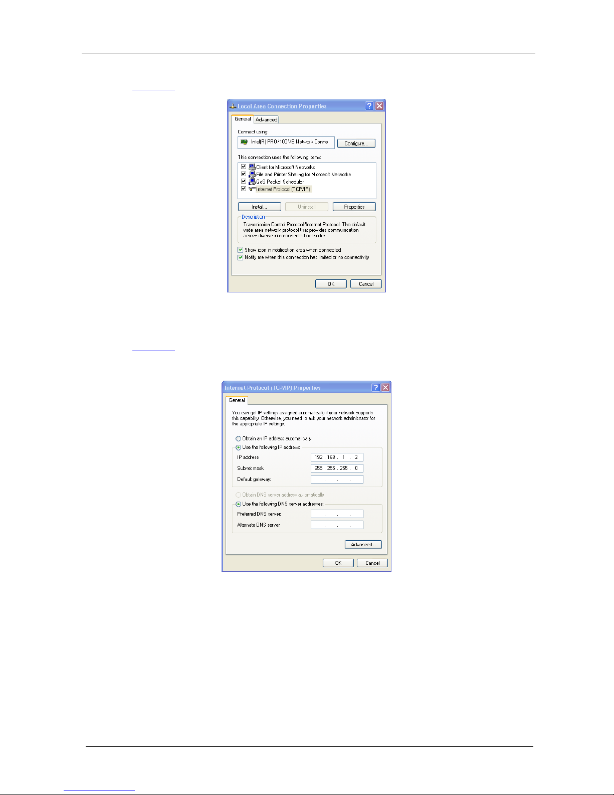
5. Select the Internet Protocol (TCP/IP) and click the Properties button (see
Figure 6).
Figure 6: Local Area Connection Properties Window
6. Select Use the following IP address, and fill in the details as shown in
Figure 7.
7. Click OK.
Figure 7: Internet Protocol (TCP/IP) Properties Window
6.2.2 Connecting via a Straight-Through Cable
You can connect the ETHERNET of the PL-50 to the Ethernet port on a
network hub or network router, via a straight-through cable with RJ-45
connectors.
im Vertrieb von
CAMBOARD Electronics
www.camboard.de
Tel. 07131 911201
Fax 07131 911203
ce-info@camboard.de
Page 15

Connecting the PL-50 Power Controller - Monitor
11
6.2.3 Configuring the Ethernet Port Initially
To initially configure the Ethernet port, download the K-UPLOAD Ethernet
configuration software
1
Follow these steps to configure the port:
. Extract the file to a folder and create a shortcut on
your desktop to the file.
1. Double click the desktop icon
the K-UPLOAD screen appears:
Figure 8: K-UPLOAD Main Screen
2. Click the Connect button.
The Connect screen appears as follows:
1 From the Kramer Web site at http://www.kramerelectronics.com
im Vertrieb von
CAMBOARD Electronics
www.camboard.de
Tel. 07131 911201
Fax 07131 911203
ce-info@camboard.de
Page 16

KRAMER: SIMPLE CREATIVE TECHNOLOGY
Connecting the PL-50 Power Controller - Monitor
12
Figure 9: Connect Screen
3. Connect a USB cable from a USB port on the PC to the USB port on the
PL-50 (you can also connect to the PC via the Ethernet or a serial connector).
4. Check USB as the connection method and select the com port from the USB
drop down list.
5. Click Connect.
The K-UPLOAD screen appears.
Figure 10: Device Properties Screen
6. If required, make changes and click Save. If not, click Exit.
im Vertrieb von
CAMBOARD Electronics
www.camboard.de
Tel. 07131 911201
Fax 07131 911203
ce-info@camboard.de
Page 17

Connecting the PL-50 Power Controller - Monitor
13
6.3 Controlling via the Embedded Web Pages
The embedded Web page can be used to remotely operate the PL-50 via the
Ethernet (see section
6.2).
6.3.1 Setting the Embedded Web Page
Before you use the embedded Web pages to control the PL-50 via the
Ethernet, check that the Java™ software is installed on your computer. If not,
download it from:
www.java.com.
A description of each Web page appears if you hover with your mouse over the
question mark that appears on the left side of the screen.
To control the PL-50 via the embedded Web page, make sure that it is
connected to the Ethernet port of your computer and do the following:
1. Open your Internet browser.
2. Type the unit’s IP number
1
in the address bar of your browser (or the name, if
using DHCP):
Figure 11: Typing the IP Number
The following window appears:
Figure 12: Loading the Embedded Web Pages
1 The default IP number is 192.168.1.39, and may be changed by the system integrator
im Vertrieb von
CAMBOARD Electronics
www.camboard.de
Tel. 07131 911201
Fax 07131 911203
ce-info@camboard.de
Page 18
KRAMER: SIMPLE CREATIVE TECHNOLOGY
Connecting the PL-50 Power Controller - Monitor
14
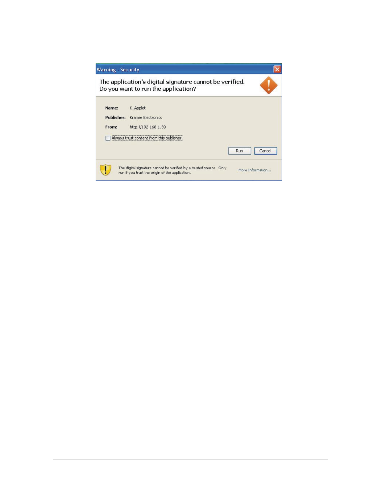
Check that Java and JavaScript is enabled in your browser. The following
window appears:
Figure 13: Running the Application
3. Click Run.
The PL-50 front panel is displayed on your screen (see
Figure 14).
The Web embedded screens let you control the PL-50 via the Ethernet. The
menu appears on the left side of the screen.
The web embedded pages include a security system (see Section
6.3.8.1). If
the security system is disabled (for example, when you use the embedded Web
pages for the first time), the embedded Web pages can be accessed, and the
parameters changed by anyone.
im Vertrieb von
CAMBOARD Electronics
www.camboard.de
Tel. 07131 911201
Fax 07131 911203
ce-info@camboard.de
Page 19

Connecting the PL-50 Power Controller - Monitor
15
6.3.2 The Panel Screen
The Panel screen lets you select one or more channels in order to read the
Standby or Active values and turn the power outlet ON/OFF:
Figure 14: HOME Embedded Web Page
The connection icon on the top right screen indicates whether the machine is
connected to your PC
or not .
Click the on-screen channel buttons:
1
2
3
4
5
Figure 15: Selecting a Channel
Each channel button includes red and green indicators. If the indicators appear
bright, the Standby or Active values are measured (channel 3 in the example in
Figure 15). Otherwise, these values were not measured.
The Help Box
This is the main panel window. In this window you can control the channels.
im Vertrieb von
CAMBOARD Electronics
www.camboard.de
Tel. 07131 911201
Fax 07131 911203
ce-info@camboard.de
Page 20

KRAMER: SIMPLE CREATIVE TECHNOLOGY
Connecting the PL-50 Power Controller - Monitor
16
6.3.3 The Scheduler Screen
The Scheduler screen lets you schedule the operation of the outlets on a
weekly basis.
Figure 16 and Table 4 define the Scheduler screen:
Figure 16: The Scheduler Screen
Table 4: The Scheduler Screen Features
Feature
Function
DATE/TIME SETTINGS Set the current date and time
Click Read to read the machine settings
Click Submit to accept the date and time settings
Click From PC to acquire the date and time from your PC (and
then press submit to accept settings)
SCHEDULER PROGRAMMING Select a channel for scheduling
1
Select the day or days of the week for scheduling
Select the time schedule for the selected channel(s): the Time ON
and the Time OFF
You can select more than one active period per channel, per day
Click Add to add the schedule for the selected channel(s)
Click Read to read
2
Click Clear All to clear the scheduling table
the current schedule stored in the machine
3
Click Submit to save the current scheduling table to the machine
1 Or several channels, or all the channels
2 The schedule stored in the machine overwrites the data displayed on the scheduler
3 This clears the schedule on the screen only, not in the machine
im Vertrieb von
CAMBOARD Electronics
www.camboard.de
Tel. 07131 911201
Fax 07131 911203
ce-info@camboard.de
Page 21

Connecting the PL-50 Power Controller - Monitor
17
After scheduling the outlets, the Scheduler screen appears as follows:
Figure 17: Scheduling the Outlets
In Figure 17, the channels are scheduled at different times. For example:
• On Monday, Channel 2 will be ON from 12:00 to 13:00 and Channel 5
will be ON from 12:00 to 14:00
• On Tuesday, Channel 2 will be ON from 08:00 to 09:31, from 12:00 to
14:00 and from 15:00 to 18:00.
• On Tuesday all the channels are scheduled to be ON from 08:00 to 09:31
and on Thursday Channels 1, 4 and 5 are scheduled to be ON from 15:00
to 18:00 (see section
6.3.7 for setting the power ON/OFF order)
You can clear a checkbox next to a time period setup in the scheduler table to
delete a scheduled time period. Click Submit to save the schedule to the PL-50.
HELP BOX
This page lets you view and set the ON/OFF scheduling of the channel. Note,
that the device will store the new scheduling only after you click "Submit".
You can also view and set the current time.
im Vertrieb von
CAMBOARD Electronics
www.camboard.de
Tel. 07131 911201
Fax 07131 911203
ce-info@camboard.de
Page 22

KRAMER: SIMPLE CREATIVE TECHNOLOGY
Connecting the PL-50 Power Controller - Monitor
18
6.3.4 The Channel Settings Screen
Figure 18 and Table 5 define the Channel Settings screen:
Figure 18: The Channel Settings Screen
Table 5: The Channel Settings Screen Features
Feature Function
Power Control: Set, for each channel whether it will be controlled manually (by the Panel screen
or the front panel buttons) or by the scheduler
In this example, channels 1, 2 and 5 are manually controlled, while channels 3
and 4 are controlled by the scheduler
Groups: Assign the channel to one of three groups only in the manual mode
1
Figure 18
.
For example, in Channel 1 and Channel 2 are assigned to group 1 and
will operate concurrently in the manual setting
In this example, channels 1 and 2 are assigned to group 1, so pressing one of
them will also activate the other
HELP BOX
In this page you can view and set the channels Power Control (Manual or
Schedule) you can also view and set Groups of channels to act together.
1 A channel that is scheduled overrides the group manual setting
im Vertrieb von
CAMBOARD Electronics
www.camboard.de
Tel. 07131 911201
Fax 07131 911203
ce-info@camboard.de
Page 23

Connecting the PL-50 Power Controller - Monitor
19
6.3.5 The Alerts Screen
Figure 19 and Table 6 define the Alerts screen:
Figure 19: The Alerts Screen
Table 6: The Alerts Screen Features
Feature
Function
Alert Triggers: Select the event that will trigger an alarm:
Check the Enable box to enable the event and action taken or clear to disable
The events:
TO OFF – the outlet turns OFF (the channel button is off)
TO ON – the outlet turns ON (the channel button is on)
TO ACTIVE – the green LED is ON
TO STANDBY – the orange LED is ON
TO NONE – the outlet is disconnected
ANY CHANGE – any change in the current status
Read: click to read the data stored in the machine
Submit: click to submit changes
Alarm
configuration:
Relay Starts As: set the relay status to closed or open according to the relay
installation. For example, if the alarm is installed so that in the closed state the
alarm is off set it to Closed
Duration: set the duration of the alarm in seconds
Test Alarm: click this button to test the alarm, click again to silence it
An alarm icon appears on the top right side of the screen. Stop the alarm by
clicking the Alarm icon (see
Figure 20)
Read: click to read the data stored in the machine
Submit: click to submit changes
im Vertrieb von
CAMBOARD Electronics
www.camboard.de
Tel. 07131 911201
Fax 07131 911203
ce-info@camboard.de
Page 24

KRAMER: SIMPLE CREATIVE TECHNOLOGY
Connecting the PL-50 Power Controller - Monitor
20
After setting the alarms, the Alerts screen appears as follows:
Figure 20: Setting the Alarms
In this example, Channel 2 and Channel 3 are enabled, and the events (TO
ACTIVE and TO ON, respectively) trigger the ALARM
The duration of the alarm is 60 seconds and it will activate both the relay
alarm and the digital control alarm. Click Test Alarm to test the alarm.
HELP BOX
This page lets you view and set all the Alerts the device will trigger. You can
also view and set the alarm configuration.
im Vertrieb von
CAMBOARD Electronics
www.camboard.de
Tel. 07131 911201
Fax 07131 911203
ce-info@camboard.de
Page 25

Connecting the PL-50 Power Controller - Monitor
21
6.3.6 The Power Measurement Screen
Figure 21 and Table 7 define the Power Measurement screen:
Figure 21: The Power Measurement Screen
Table 7: The Power Measurement Screen Features
Feature
Function
Power Status Status indicator per channel:
Measured – if the standby and active values are available (Channel 4 in this
example)
Not Measured – if one or both of the values were not measured (for
example, Channel 1)
Power Measurement Click Standby or active to measure the standby and/or Active values for an
outlet connected to a channel (once measured, the status changes from
“Not Measured” to “Measured”)
Click clear to clear the Standby and Active data for that channel
1
HELP BOX
This page lets you start the "Standby" and "Active" mode measurement
process. You can also clear the current "Standby" and "Active" thresholds.
1 You can also reset the data for all the channels by pressing the reset button located on the rear panel of the machine (see
Figure 2 and Figure 3) and plugging the power ON while pressing
im Vertrieb von
CAMBOARD Electronics
www.camboard.de
Tel. 07131 911201
Fax 07131 911203
ce-info@camboard.de
Page 26

KRAMER: SIMPLE CREATIVE TECHNOLOGY
Connecting the PL-50 Power Controller - Monitor
22
6.3.7 The Power ON/OFF Order Screen
The Power ON/OFF Order screen lets you determine the power ON and OFF
order for channels that are scheduled to switch ON/OFF simultaneously. This
is very convenient for systems that require a specific power up or shut down
sequence.
Figure 22 and Table 8 define Switch Order screen:
Figure 22: The Power ON/OFF Order Screen
Table 8: The Power ON/OFF Order Screen Features
Feature Function
Power ON /OFF Order By default, the channels are set to switch ON/OFF in sequence (from 1 to 5).
Use the up and down arrows to set to the desired order
ON/OFF Delay Set the switching ON/OFF delay time for each channel in the switching
sequence
Read Click to read the switching order stored in the machine
Submit Click to submit changes
im Vertrieb von
CAMBOARD Electronics
www.camboard.de
Tel. 07131 911201
Fax 07131 911203
ce-info@camboard.de
Page 27
Connecting the PL-50 Power Controller - Monitor
23
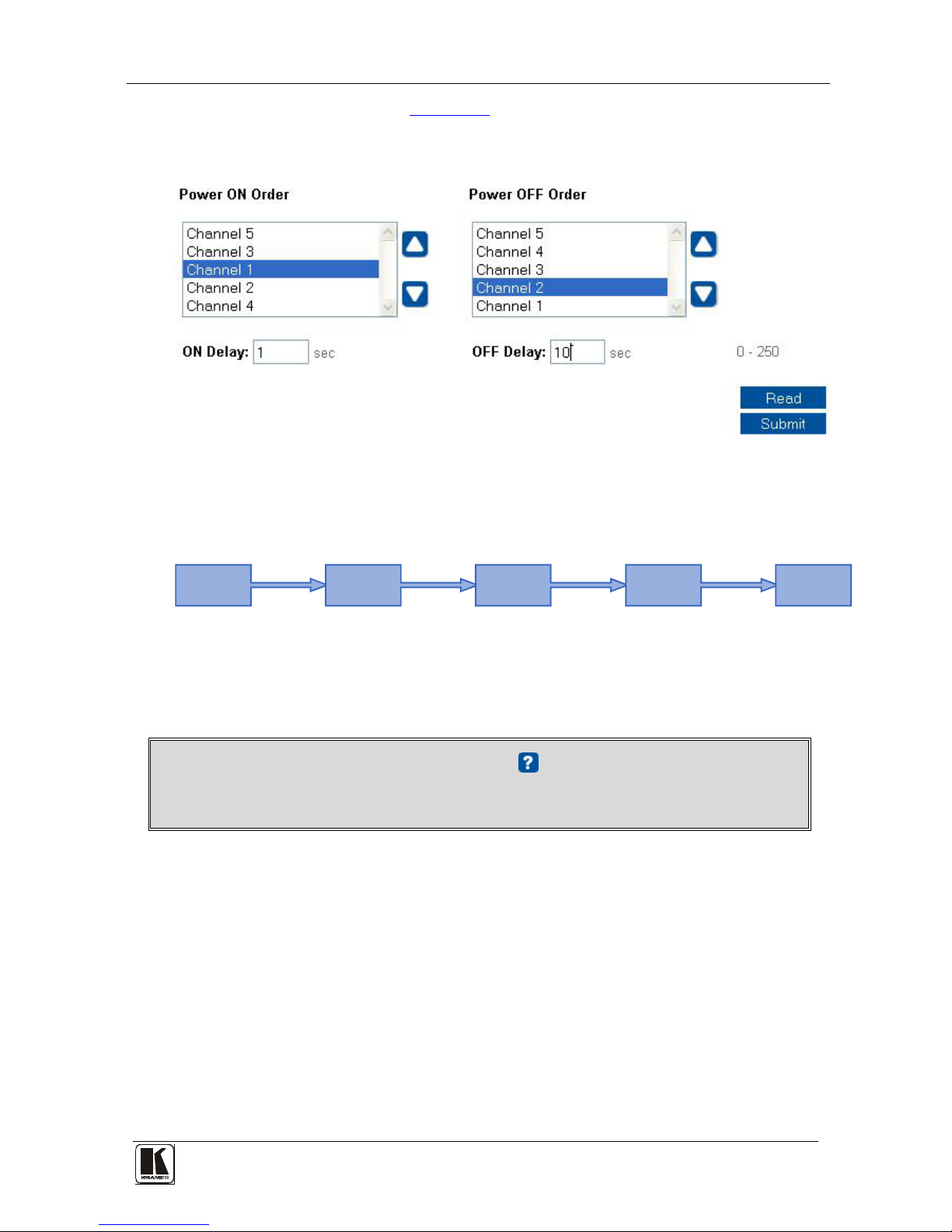
In the example illustrated in Figure 23, the Power OFF Order is set from
5 to 1 with a 10 second delay time before each channel in the sequence is
switched OFF:
Figure 23: Power ON Order Example
The system switches ON according to the Power ON Order, with a 1 second
delay before powering ON each channel:
1sec
Delay
1sec
Delay
1sec
Delay
1sec
Delay
Power ON
Channel 5
Power ON
Channel 3
Power ON
Channel 1
Power ON
Channel 2
Power ON
Channel 4
Figure 24: Switching ON Sequence Example
If an outlet is not connected, the sequence skips over that channel (and its
switching delay time as well) and continues to the next channel in the
sequence.
HELP BOX
This page lets you set the power ON and OFF order and delay.
im Vertrieb von
CAMBOARD Electronics
www.camboard.de
Tel. 07131 911201
Fax 07131 911203
ce-info@camboard.de
Page 28

KRAMER: SIMPLE CREATIVE TECHNOLOGY
Connecting the PL-50 Power Controller - Monitor
24
6.3.8 The Configurations Screen
The Configurations page lets you view and change some Ethernet settings
1
Figure 25
(see ) and also set the security level.
To change Configuration definitions:
1. Click Configurations. The Configurations Web page appears.
2. Change the definitions as required.
3. Click the Submit button to apply changes
2
4. Click Yes.
A window appears announcing that the configuration has been successfully
changed.
. A window appears asking if you
are sure you want to change the network settings.
5. Click OK
6. If the IP number had been changed, close the browser and reload the Web
page.
Figure 25: Configurations Embedded Web Page
HELP BOX
This page lets you view and set the device configuration.
1 The model name, serial number, firmware version and MAC address
2 Or Cancel to cancel changes
im Vertrieb von
CAMBOARD Electronics
www.camboard.de
Tel. 07131 911201
Fax 07131 911203
ce-info@camboard.de
Page 29
Connecting the PL-50 Power Controller - Monitor
25
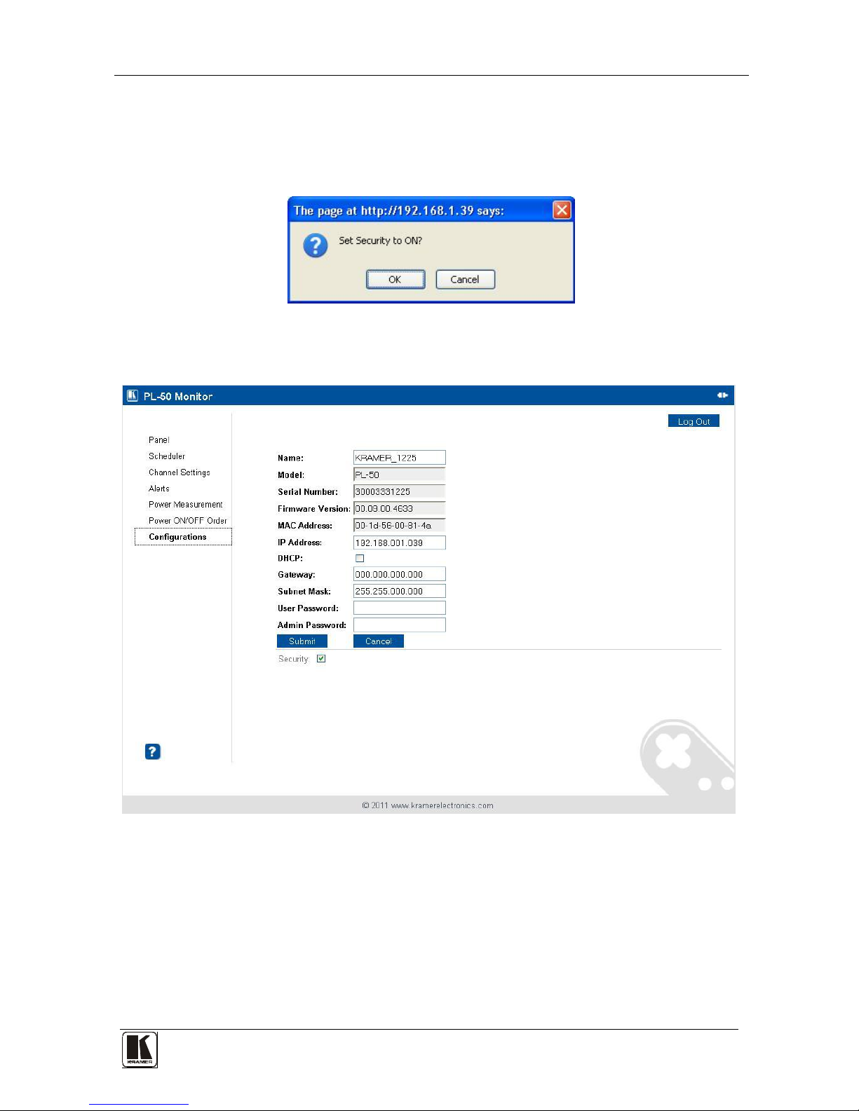
If the security system is disabled, the embedded Web pages can be accessed,
and the parameters changed by anyone.
Check the Security box to enable the security system. The following window
appears:
Figure 26: Enable Security System
Click OK to enable the security system:
Figure 27: Security System Enabled
im Vertrieb von
CAMBOARD Electronics
www.camboard.de
Tel. 07131 911201
Fax 07131 911203
ce-info@camboard.de
Page 30

KRAMER: SIMPLE CREATIVE TECHNOLOGY
Connecting the PL-50 Power Controller - Monitor
26
6.3.8.1 The Security System
Set the user password and Admin password
1
The security system includes three levels of security:
(by default, the passwords for
both User and Admin are empty fields).
• Pre-authorized mode (the security box is checked) – the Web pages are
disabled and you have to enter either the User or Admin password to
access the system (see
Figure 28)
• User mode – monitor the system and switch outlets ON or OFF
• Admin mode – control the system and change any of the parameters
Figure 28: User Login
At any time you can log out by clicking the Log Out button on the top right
side of the Web page (see
Figure 27).
HELP BOX
Please log in as USER or ADMIN.
1 Both the Admin and the User passwords are reset to their default values when pressing the reset button located on the rear
panel of the machine (see
Figure 2 and Figure 3) and plugging the power ON while pressing
im Vertrieb von
CAMBOARD Electronics
www.camboard.de
Tel. 07131 911201
Fax 07131 911203
ce-info@camboard.de
Page 31
Operating Your PL-50 Power Controller – Monitor
27
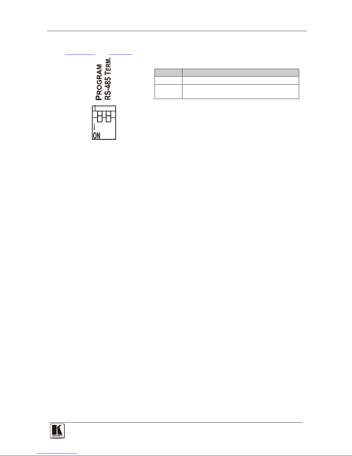
6.4 DIP-switch Settings
Figure 29 and Table 9 define the DIP-switches:
1 2
Table 9: DIP-switch Definitions
DIP
Function:
1 PROGRAM, for factory use only
2
ON for RS-485 Line Termination with 120Ω;
OFF for no RS-485 Line Termination
Figure 29: SETUP DIP-switches
7 Operating Your PL-50 Power Controller – Monitor
You can operate your PL-50 via:
• The front panel buttons
• Remotely, by USB, RS-485 or RS-232 serial commands transmitted by a
touch screen system, PC, or other serial controller
• The Ethernet
• Remotely, from the Kramer Infrared Remote Control Transmitter or the
infrared remote extension cable transmitter
Powering up PL-50 unit, recalls the previous settings (that is, the state of the unit
when it was powered down) from the non-volatile memory.
7.1 Calibrating via the Front Panel Buttons
Prior to monitoring the PL-50 outlets, each outlet needs to be measured for its
standby and Active modes.
To set the Active mode, do the following:
1. Press one or more OUT buttons to select the channels for which you want to
measure the standby or active modes.
The selected buttons illuminate.
2. Set the connected units to the Active mode.
3. Press the PRESET LEVEL ACTIVE button.
The selected orange OUT buttons, and their related ACTIVE green LEDs
blink.
4. Press each of the selected orange blinking buttons to initialize the
measurement.
The ACTIVE green LED blinks until measurement is complete.
im Vertrieb von
CAMBOARD Electronics
www.camboard.de
Tel. 07131 911201
Fax 07131 911203
ce-info@camboard.de
Page 32

KRAMER: SIMPLE CREATIVE TECHNOLOGY
Operating Your PL-50 Power Controller – Monitor
28
To set the Standby mode
1
1. Press one or more OUT buttons to select the channels for which you want to
measure the standby or active modes.
The selected buttons illuminate.
, do the following:
2. Set the connected units to the Standby mode
3. Press the PRESET LEVEL STANDBY button.
The selected orange OUT buttons, and their related STANDBY orange LEDs
blink.
4. Press each of the selected orange blinking buttons to initialize the
measurement.
The STANDBY orange LED blinks until measurement is complete.
To reset the active and standby values on all channels, press the RESET
button on the rear panel while turning the power ON.
You can measure the Active and Standby values as well as reset individual
channels via the embedded Web pages (see section
6.3.2).
1 The unit should be powered up and running under typical conditions when the measurements are made
im Vertrieb von
CAMBOARD Electronics
www.camboard.de
Tel. 07131 911201
Fax 07131 911203
ce-info@camboard.de
Page 33

Flash Memory Upgrade
29
8 Flash Memory Upgrade
The PL-50 uses a microcontroller that runs firmware located in FLASH
memory. The latest version of firmware can be downloaded from the Kramer
Web site at
www.kramerelectronics.com and updated in minutes using the
K-UPLOAD and the following procedures.
Before firmware upgrade:
Close the embedded Web pages
Do not press the front panel buttons
8.1 Upgrading the Firmware
To upgrade the PL-50 firmware:
1. Download the firmware file from the Internet (see section
8.1.1)
2. Connect a PC to the PL-50 (see section
8.1.2)
3. Update the firmware using the K-UPLOAD (see section
8.1.3)
8.1.1 Download the Firmware
To download the latest firmware file
1
1. Go to the Kramer Web site at
from the Internet:
www.kramerelectronics.com.
2. Navigate to SUPPORT / Software Firmware Updates.
3. Click on the link of the firmware that applies to your product. Download it
and save it to disk.
4. Extract the file to a folder (for example, C:\Program Files\Kramer Flash).
8.1.2 Connect a PC to the PL-50
To connect a PC to the PL-50, make any one of the following connections:
• Connect a serial cable from an RS-232 9-pin D-sub rear panel port on the
PC to the PL-50.
• Connect a USB cable from a USB port on the PC to the USB port on the
PL-50
• Connect an RJ-45 Ethernet cable from the Ethernet port on the PC to the
Ethernet port on the PL-50 as explained in section
6.2
1 The files indicated in this section are given as an example only. File names are liable to change from time to time
im Vertrieb von
CAMBOARD Electronics
www.camboard.de
Tel. 07131 911201
Fax 07131 911203
ce-info@camboard.de
Page 34

KRAMER: SIMPLE CREATIVE TECHNOLOGY
Flash Memory Upgrade
30
8.1.3 Update the Firmware
To update the firmware, perform the following steps:
1. Open the K-UPLOAD software
1
by double-clicking the desktop icon
K-UPLOAD. The K-UPLOAD screen appears
2
:
Figure 30: K-UPLOAD Screen
2. Click the Connect button.
The Connect Window appears (see
Figure 31).
Figure 31: Connect Ethernet by IP Number
1 You can download and install the latest version of K-UPLOAD from http://www.kramerelectronics.com.
2 The screens appearing in this manual are examples of the process. The actual screens may differ in their content.
im Vertrieb von
CAMBOARD Electronics
www.camboard.de
Tel. 07131 911201
Fax 07131 911203
ce-info@camboard.de
Page 35

Flash Memory Upgrade
31
3. If you are upgrading using an Ethernet connection, check Ethernet.
To reset the device address to the factory default address, click Default and the
address 192.168.1.39 appears.
If you are upgrading using:
RS-232 check Serial, and select the COM port to connect
USB, check USB and select the USB device to connect
4. Click Connect.
Note: If you try to connect to a device and the time out message appears
1
Figure 32
(see
), click CLOSE and verify that the device is powered on, the cable
connection is good, the switch on the device is set to “Program”, and that you
are trying to connect by the correct method and then click Connect again.
Figure 32: Connection Time Out Message
The machine is now connected:
1 Other Error messages may appear, such as “No USB devices were found” or “This driver is not a valid driver for this unit”
and so on
im Vertrieb von
CAMBOARD Electronics
www.camboard.de
Tel. 07131 911201
Fax 07131 911203
ce-info@camboard.de
Page 36

KRAMER: SIMPLE CREATIVE TECHNOLOGY
Flash Memory Upgrade
32
Figure 33: K-UPLOAD Connected
Note: In the Device Properties section, you can update any of the active fields
that have a white background. After making any changes, click Save.
5. Click the Browse button, select the file from the Open window and then click
Open.
Figure 34: Open the Firmware File
im Vertrieb von
CAMBOARD Electronics
www.camboard.de
Tel. 07131 911201
Fax 07131 911203
ce-info@camboard.de
Page 37

Flash Memory Upgrade
33
6. Click the UPLOAD button to begin the file transfer.
The Warning window appears:
Figure 35: Warning Window
7. Click OK to continue.
The upload progress appears in the Progress box:
Figure 36: Upload Progress
After loading the firmware file, wait for completion of the firmware upgrade:
im Vertrieb von
CAMBOARD Electronics
www.camboard.de
Tel. 07131 911201
Fax 07131 911203
ce-info@camboard.de
Page 38

KRAMER: SIMPLE CREATIVE TECHNOLOGY
Flash Memory Upgrade
34
8. When the update is finished, the restart message appears:
Figure 37: Restart Message
9. Click Restart now to close K-UPLOAD and remove the cable that connects
the PL-50 to the PC.
im Vertrieb von
CAMBOARD Electronics
www.camboard.de
Tel. 07131 911201
Fax 07131 911203
ce-info@camboard.de
Page 39

Technical Specifications
35
8.2 Changing the Device Parameters
To change the device parameters do the following:
1. Connect a PC to the PL-50 (see section
8.1.2).
2. Open K-UPLOAD (see
Figure 30).
3. Click the Connect button to open the Connect window (see
Figure 31).
4. Choose the appropriate type of connection: Ethernet, Serial or USB, and click
Connect.
The Connect window disappears and the Device Properties become visible.
5. Change the parameters as required and then click Save.
9 Technical Specifications
Table 10 includes the technical specifications:
Table 10: Technical Specifications
1
INPUT POWER SOURCE:
of the PL-50
For Europe: 230V AC, 50/60Hz, 10VA, internal
For the USA 130V AC, 130V AC, 50/60Hz, 10VA, internal
OUTPUTS: For Europe: 5 x 220-240V AC outputs, total load of 10A Max.
For the USA: 5 x 100-120V AC outputs, total load of 10A Max.
DIMENSIONS: 19-inch (W ), 7-inch (D) 1U (H) rack-mountable
WEIGHT: 2.7kg (6lbs) approx.
ACCESSORIES: Power cord, Windows®-based Kramer control software,
Infrared remote control transmitter
1 Specifications are subject to change without notice
im Vertrieb von
CAMBOARD Electronics
www.camboard.de
Tel. 07131 911201
Fax 07131 911203
ce-info@camboard.de
Page 40

KRAMER: SIMPLE CREATIVE TECHNOLOGY
Kramer Protocol 3000
36
10 Kramer Protocol 3000
The Ethernet/USB/RS-232/RS-4851 communication protocol
2
10.1 Protocol 3000 Syntax
lets you control
the machine from any standard terminal software (for example, Windows®
HyperTerminal Application).
Host message format:
Start
Address (optional)
Body
Delimiter
#
Destination_id@ message
CR
Simple command (commands string with only one command without
addressing):
start
body
delimiter
#
Command SP Parameter_1,Parameter_2,… CR
Commands string (formal syntax with commands concatenation and
addressing):
Start Address Body Delimiter
#
Destination_id@
Command_1 Parameter1_1,Parameter1_2,…|
Command_2 Parameter2_1,Parameter2_2,…|
Command_3 Parameter3_1,Parameter3_2,…|…
CR
Device message format:
Start
Address (optional)
Body
Delimiter
~ Sender_id@ message CR LF
Device long response (Echoing command):
Start
Address (optional)
Body
Delimiter
~ Sender_id@
command SP [param1 ,param2 …] result
CR LF
CR = Carriage return (ASCII 13 = 0x0D)
LF = Line feed (ASCII 10 = 0x0A)
SP = Space (ASCII 32 = 0x20)
1 RS-232/RS-485 use a data rate of 115200 baud, with no parity, 8 data bits, and 1 stop bit
2 Not available at the time of printing. Refer to our Web site at http://www.kramerelectronics.com for details
im Vertrieb von
CAMBOARD Electronics
www.camboard.de
Tel. 07131 911201
Fax 07131 911203
ce-info@camboard.de
Page 41

Kramer Protocol 3000
37
10.2 Command Terms
Command:
Sequence of ASCII letters ('A'-'Z', 'a'-'z' and '-').
Command will separate from parameters with at least single space.
Parameters:
Sequence of Alfa-Numeric ASCII chars ('0'-'9','A'-'Z','a'-'z' and some special characters for specific commands), parameters
are separated by commas.
Message string:
Every command entered as part of a message string begins with a message starting character and ends with a message closing
character.
Note: A string can contain more than one command. Commands are separated by a pipe ( '|' ) character.
Message starting char:
'#' for host command/query.
'~' for machine response.
Device address (Optional when directly connected to the device)
K-NET Device ID or MACHINE NUMBER followed by '@'
(ex. #02@
CRLF )
Query sign
'?' follows some commands to define a query request.
All outputs sign
'*' defines all outputs.
Message closing character
CR – For host messages; carriage return (ASCII 13)
CRLF – For machine messages; carriage return (ASCII 13) + line-feed (ASCII 10)
Commands chain separator char:
When a message string contains more than one command, a pipe ( '|' ) character separates each command.
Spaces between parameters or command terms are ignored.
Entering Commands:
You can directly enter all commands using a terminal with ASCII communications software, such as HyperTerminal,
Hercules, etc. Connect the terminal to the serial, Ethernet, or USB port on the Kramer device. To enter
CR , press the Enter
key.
(
LF is also sent but is ignored by command parser).
For commands sent from some non-Kramer controllers like Crestron, some characters require special coding (such as, /X##).
Refer to the controller manual.
Command forms:
Some commands have short name syntax beside the full name to allow faster typing, response is always in long syntax.
Command chaining:
Multiple commands can be chained in the same string. Each command is delimited by a pipe character ( '|' ). When chaining
commands, enter the message starting character and the message closing character only once, at the beginning of the
string and at the end.
Commands in the string do not execute until the closing character is entered.
A separate response is sent for every command in the chain.
maximum string length:
64 characters.
im Vertrieb von
CAMBOARD Electronics
www.camboard.de
Tel. 07131 911201
Fax 07131 911203
ce-info@camboard.de
Page 42

KRAMER: SIMPLE CREATIVE TECHNOLOGY
Kramer Protocol 3000
38
10.3 Common Commands
#
Cmd Short Description Command Type Permission
Protocol handshaking Common-mandatory End User
Usage:
Syntax Response
#CR ~OKCRLF
BUILD-DATE?
Cmd Short Description Command Type Permission
Read device build date Common-mandatory End User
Usage:
Syntax Response
MODEL?
Cmd Short Description Command Type Permission
Read device model Common-mandatory End User
Usage:
Syntax Response
MODEL?
MODEL MACHINE_MODEL
PROT-VER?
Cmd Short Description Command Type Permission
Read device protocol version Common-mandatory End User
Usage:
Syntax Response
RESET
Cmd Short Description Command Type Permission
Reset device Common-mandatory Administrator
Usage:
Syntax Response
RESET RESET OK
SN?
Cmd Short Description Command Type Permission
Read device serial number Common-mandatory End User
Usage:
Syntax Response
SN?
SN SERIAL_NUMBER
VERSION?
Cmd Short Description Command Type Permission
Read device firmware version Common-mandatory End User
Usage:
Syntax Response
VERSION?
VERSION MAJOR .MINOR .BUILD .REVISION
im Vertrieb von
CAMBOARD Electronics
www.camboard.de
Tel. 07131 911201
Fax 07131 911203
ce-info@camboard.de
Page 43

Kramer Protocol 3000
39
FACTORY
Cmd Short Description Command Type Permission
Reset to factory default config Common Administrator
Usage:
Syntax Response
NAME
Cmd Short Description Command Type Permission
Set machine (DNS) name Common Administrator
Usage:
Syntax Response
NAME MACHINE_NAME NAME MACHINE_NAME RESULT
NAME?
Cmd Short Description Command Type Permission
Get machine (DNS) name Common End User
Usage:
Syntax Response
NAME?
NAME MACHINE_NAME
*Note: The machine name is not the same as the model name. The machine name is used to identify a specific
machine or a network in use (with DNS feature on).
MACHINE_NAME = Up to 14 alphameric chars.
* Machine factory name = Model name + last 4 digits from serial number.
NAME-RST
Cmd Short Description Command Type Permission
Reset machine name to
factory default (DNS)
Common Administrator
Usage:
Syntax Response
NAME-RST
NAME-RST MACHINE_FACTORY_NAME RESULT
TIME
Cmd Short Description Command Type Permission
Set device time and date Common Administrator
Usage:
Syntax Response
TIME DATE_TIME TIME DATE_TIME RESULT
Note: Time setting commands require administrator authorization.
TIME?
Cmd Short Description Command Type Permission
Get device time and date Common End User
Usage:
Syntax Response
TIME?
TIME? DATE_TIME
im Vertrieb von
CAMBOARD Electronics
www.camboard.de
Tel. 07131 911201
Fax 07131 911203
ce-info@camboard.de
Page 44
KRAMER: SIMPLE CREATIVE TECHNOLOGY
Kramer Protocol 3000
40
UPGRADE
Cmd Short Description Command Type Permission
Execute firmware upgrade Common Administrator
Usage:
Syntax Response
UPGRADE UPGRADE OK
Firmware usually uploads to a device via a command like LDFW. The device may need to be reset to complete
the process.
10.4 Result and Error Codes
Syntax
Command ran successfully, no error.
COMMAND PARAMETERS OK
Protocol Errors:
Syntax error ERR001
Command not available for this device ERR002
Parameter is out of range ERR003
Unauthorized access (command run without the matching login). ERR004
10.5 23BSecurity Commands
LOGIN
Cmd Short Description Command Type Permission
Login Security No Security
Usage:
Syntax Response
LOGIN ID , PASS
ID = User/Admin
PASS = 0-15 length ASCII characters without #, ~, @, ?
LOGIN ID , PASS RESULT
LOGIN?
Cmd Short Description Command Type Permission
Query Login Security No Security
Usage:
Syntax Response
LOGIN?
LOGIN ID
LOGOUT
Cmd Short Description Command Type Permission
Logout Security No Security
Usage:
Syntax Response
LOGOUT
LOGOUT RESULT
im Vertrieb von
CAMBOARD Electronics
www.camboard.de
Tel. 07131 911201
Fax 07131 911203
ce-info@camboard.de
Page 45

Kramer Protocol 3000
41
PASS
Cmd Short Description Command Type Permission
Set password Security Administrator
Usage:
Syntax Response
PASS ID , PASS PASS ID , PASS RESULT
PASS?
Cmd Short Description Command Type Permission
Query password Security Administrator
Usage:
Syntax Response
PASS? ID PASS ID , PASS RESULT
SECUR
Cmd Short Description Command Type Permission
Start/Stop Security Security Administrator
Usage:
Syntax Response
SECUR ON/OFF
ON/OFF = 0 or OFF, 1 or ON
SECUR ON/OFF RESULT
SECUR?
Cmd Short Description Command Type Permission
Query Start/Stop Security Security No Security
Usage:
Syntax Response
SECUR?
SECUR ON/OFF
10.6 Network Setting Commands
These commands are used by network devices running Protocol 3000.
ETH-PORT
Cmd Short Description Command Type Permission
ETHP Change protocol Ethernet port Ethernet Administrator
Usage:
Syntax Response
ETH-PORT PROTOCOL , PORT ETH-PORT PROTOCOL ,PORT RESULT
ETH-PORT?
Cmd Short Description Command Type Permission
ETHP? Get protocol Ethernet port Ethernet End User
Usage:
Syntax Response
ETH-PORT? PROTOCOL ETH-PORT PROTOCOL , PORT
PROTOCOL = TCP/UDP (transport layer protocol)
PORT = Ethernet port that accepts Protocol 3000 commands
1-65535 = User defined port
im Vertrieb von
CAMBOARD Electronics
www.camboard.de
Tel. 07131 911201
Fax 07131 911203
ce-info@camboard.de
Page 46

KRAMER: SIMPLE CREATIVE TECHNOLOGY
Kramer Protocol 3000
42
NET-DHCP
Cmd Short Description Command Type Permission
NTDH Set DHCP mode Ethernet Administrator
Usage:
Syntax Response
NET-DHCP DHCP_MODE NET-DHCP DHCP_MODE RESULT
DHCP_MODE =
‘0’ – Don't use DHCP (Use IP set by factory or IP set command).
‘1’ – Try to use DHCP, if unavailable use IP as above.
NET-DHCP?
Cmd Short Description Command Type Permission
NTDH? Get DHCP mode Ethernet End User
Usage:
Syntax Response
NET-DHCP?
NET-DHCP DHCP_MODE
NET-GATE
Cmd Short Description Command Type Permission
NTGT Set Gateway Ethernet Administrator
Usage:
Syntax Response
NET-GATE GATEWAY_ADDRESS
GATEWAY ADDRESS = gateway IP address
(ex: 192.168.001.001)
NET-GATE GATEWAY_ADDRESS RESULT
NET-GATE?
Cmd Short Description Command Type Permission
NTGT? Get Gateway Ethernet End User
Usage:
Syntax Response
NET-GATE?
NET-GATE GATEWAY_ADDRESS
NET-IP
Cmd Short Description Command Type Permission
NTIP Set IP address Ethernet Administrator
Usage:
Syntax Response
NET-IP IP_ADDRESS, (ex: 192.168.001.001) NET-IP IP_ADDRESS RESULT
NET-IP?
Cmd Short Description Command Type Permission
NTIP? Get IP address Ethernet End User
Usage:
Syntax Response
NET-IP?
NET-IP IP_ADDRESS
im Vertrieb von
CAMBOARD Electronics
www.camboard.de
Tel. 07131 911201
Fax 07131 911203
ce-info@camboard.de
Page 47

Kramer Protocol 3000
43
NET-MAC?
Cmd Short Description Command Type Permission
NTMC? Read MAC address Ethernet End User
Usage:
Syntax Response
NET-MAC?
NET-MAC MAC_ADDRESS
NET-MASK
Cmd Short Description Command Type Permission
NTMSK Set subnet mask Ethernet Administrator
Usage:
Syntax Response
NET-MASK SUBNET_MASK
Ex: 255.255.000.000
NET-MASK SUBNET_MASK RESULT
NET-MASK?
Cmd Short Description Command Type Permission
NTMSK? Get subnet mask Ethernet End User
Usage:
Syntax Response
NET-MASK?
NET-MASK SUBNET_MASK
10.7 Instruction Codes
ALARM
Cmd Short Description Command Type Permission
Device notification PL-50 No security
Usage:
Syntax Response
ALARM 1/0
1/0= On OR Off
ALARM-DURATION
Cmd Short Description Command Type Permission
Set alarm duration PL-50 Administrator
Usage:
Syntax Response
ALARM-DURATION SECONDS
SECONDS = 0–255
ALARM-DURATION SECONDS RESULT
ALARM-DURATION?
Cmd Short Description Command Type Permission
Query alarm duration PL-50 User
Usage:
Syntax Response
ALARM-DURATION?
ALARM-DURATION SECONDS
im Vertrieb von
CAMBOARD Electronics
www.camboard.de
Tel. 07131 911201
Fax 07131 911203
ce-info@camboard.de
Page 48

KRAMER: SIMPLE CREATIVE TECHNOLOGY
Kramer Protocol 3000
44
ALARM-OFF
Cmd Short Description Command Type Permission
Set alarm OFF PL-50 User
Usage:
Syntax Response
ALARM-OFF
ALARM-OFF RESULT
ALARM-ON
Cmd Short Description Command Type Permission
Set alarm ON PL-50 User
Usage:
Syntax Response
ALARM-ON
ALARM-ON RESULT
ALARM-ON?
Cmd Short Description Command Type Permission
Query alarm status PL-50 User
Usage:
Syntax Response
ALARM-ON?
ALARM-ON 1/0
1/0= On OR Off
ALARM-START-AS
Cmd Short Description Command Type Permission
Set alarm Relay mode start
PL-50 Administrator
Usage:
Syntax Response
ALARM-START-AS 1/0 ALARM-START-AS 1/0 RESULT
1/0= Open/Close
ALARM-START-AS?
Cmd Short Description Command Type Permission
Query alarm Relay mode start.
PL-50 User
Usage:
Syntax Response
ALARM-START-AS?
ALARM-START-AS 1/0
1/0= Open/Close
ALERT-REG
Cmd Short Description Command Type Permission
Alert Registration PL-50 Administrator
Usage:
Syntax Response
ALERT-REG? CHNL ALERT-REG? CHNL ,EVENT ,ACTION
CHNL = (1-5)
EVENT = (TO_OFF,TO_ON,TO_FULL,TO_STBY,TO_NONE,ANY_CHANGE)
ACTION = (NO_ALERT,ALARM, ALL_ALERTS)
im Vertrieb von
CAMBOARD Electronics
www.camboard.de
Tel. 07131 911201
Fax 07131 911203
ce-info@camboard.de
Page 49

Kramer Protocol 3000
45
ALERT-REG?
Cmd Short Description Command Type Permission
Query Alert Registration PL-50 User
Usage:
Syntax Response
ALERT-REG? CHNL ALERT-REG? CHNL ,EVENT ,ACTION
CHNL = (1-5)
EVENT = (TO_OFF,TO_ON,TO_FULL,TO_STBY,TO_NONE,ANY_CHANGE)
ACTION = (NO_ALERT,ALARM, ALL_ALERTS)
MEASURE
Cmd Short Description Command Type Permission
Device notification PL-50
Usage:
Syntax Response
MEASURE CHNL ,MES-MODE
Query the "full" and "standby" LED status. (device will report to all protocol ports on any change)
LVL = (0 = no LEDs, 1 = standby LED on, 2 = full LED on)
CHNL = (1-5)
MES-MODE= (0=MEASURE_START, 1 = MEASURE_DONE, 2 = MEASURE_TIMEOUT)
PWR-LVL?
Cmd Short Description Command Type Permission
Query Power level PL-50 User
Usage:
Syntax Response
PWR-LVL?
PWR-LVL LVL
Query the "full" and "standby" LED status. (Device reports to all protocol ports on any change)
LVL = (0 = no LED, 1 = standby LED on, 2 = full LED on)
SCHED?
Cmd Short Description Command Type Permission
Query saved scheduling PL-50 User
Usage:
Syntax Response
SCHED? CHNL ,DAY SCHED? CHNL ,DAY ,SCHEDULINGS
CHNL = (1-5)
DAY = (1-7) OR (SUN,MON,TUE,WED,THU,FRI,SAT)
SCHEDULINGS = (start-end) example: 8:29-8:32
SWITCH
Cmd Short Description Command Type Permission
Channel switch PL-50 User
Usage:
Syntax Response
SWITCH CHNL ,STATUS SWITCH CHNL ,STATUS RESULT
CHNL = (1-5)
STATUS = (0=OFF,1=ON,2=ON-SCHEDULER,3=OFF-SCHEDULER ,4=ACTIVE-MEASURE,5=STANDBY-
MEASURE)
im Vertrieb von
CAMBOARD Electronics
www.camboard.de
Tel. 07131 911201
Fax 07131 911203
ce-info@camboard.de
Page 50

KRAMER: SIMPLE CREATIVE TECHNOLOGY
Kramer Protocol 3000
46
SWITCH?
Cmd Short Description Command Type Permission
Query channel switch PL-50 User
Usage:
Syntax Response
SWITCH? CHNL SWITCH? CHNL ,STATUS
CHNL = (1-5)
STATUS = (0=OFF,1=ON,2=ON-SCHEDULER,3=OFF-SCHEDULER ,4=ACTIVE-MEASURE,5=STANDBY-
MEASURE)
SWITCH-ORDER
Cmd Short Description Command Type Permission
Set the switch order PL-50 Administrator
Usage:
Syntax Response
SWITCH-ORDER ON/OFF, C, C, C, C, C SWITCH-ORDER ON/OFF , C, C, C, C, C RESULT
CHNL = C = (1-5) ON/OFF = ON or OFF
SWITCH-ORDER?
Cmd Short Description Command Type Permission
Query the switch order PL-50 User
Usage:
Syntax Response
SWITCH-ORDER? ON/OFF
SWITCH-ORDER ON/OFF , C, C, C, C, C
CHNL = C = (1-5) ON/OFF = ON or OFF
SWITCH-ORDER-DELAY
Cmd Short Description Command Type Permission
Set the switch order delay PL-50 Administrator
Usage:
Syntax Response
SWITCH-ORDER-DELAY ON/OFF, 0-255 sec SWITCH-ORDER-DELAY ON/OFF, 0-255 sec RESULT
ON/OFF = ON or OFF
SWITCH-ORDER-DELAY?
Cmd Short Description Command Type Permission
Query the switch order delay PL-50 User
Usage:
Syntax Response
SWITCH-ORDER-DELAY? ON/OFF SWITCH-ORDER-DELAY ON/OFF, 0-255 sec
ON/OFF = ON or OFF
im Vertrieb von
CAMBOARD Electronics
www.camboard.de
Tel. 07131 911201
Fax 07131 911203
ce-info@camboard.de
Page 51

47
LIMITED WARRANTY
WHO IS PROTECTED?
WHAT IS COVERED AND WHAT IS NOT COVERED
WHAT WE WILL PAY FOR AND WHAT WE WILL NOT PAY FOR
HOW YOU CAN GET WARRANTY SERVICE
LIMITATION OF IMPLIED WARRANTIES
EXCLUSION OF DAMAGES
CAUTION!
Kramer Electronics (hereafter ) warrants this product free from defects in material and workmanship under the
following terms .
Kramer
HOW LO NG IS THE WARRANTY
Labor and parts are warranted for seven years from the date of the first customer purchase.
Only the first purchase customer may enforce this warranty.
We will pay labor and material expenses for covered items. We will not pay for the following:
The liability of Kramer for any effective products is limited to the repair or replacement of the product at our option. Kramer shall
not be liable for:
This warranty gives you specific legal rights, and you may also have other rights, which vary from place to place.
All products returned to Kramer for service must have prior approval. This may be obtained from your dealer.
This equipment has been tested to determine compliance with the requirements of:
EN-50081: "Electromagnetic compatibility (EMC);
generic emission standard.
Residential, commercial and light industry"
EN-50082: "Electromagnetic compatibility (EMC) generic immunity standard.
Part 1: Residential, commercial and light industry environment".
CFR-47: FCC* Rules and Regulations:
Part 15: “Radio frequency devices
Subpart B Unintentional radiators”
Except as below, this warranty covers all defects in material or workmanship in this product. The following are not covered
by the warrant y:
1. Any product which is not distributed by Kramer, or which is not purchased from an authorized Kramer dealer. If you are
uncertain as to whether a dealer is authorized, please contact Kramer at one of the agents listed in the Web site
www.kramerelectronics.com.
2. Any product, on which the serial number has been defaced, modified or removed, or on which the WARRANTY VOID
TAMPERED sticker has been torn,
3. Damage, deterioration or malfunction resulting from:
i) Accident, misuse, abuse, neglect, fire, water, lightning or other acts of nature
ii) Product modification, or failure to follow instructions supplied with the product
iii) Repair or attempted repair by anyone not authorized by Kramer
iv) Any shipment of the product (claims must be presented to the carrier)
v) R emoval or installation of the product
vi) Any other cause, which does not relate to a product defect
vii) Cartons, equipment enclosures, cables or accessories used in conjunction with the product
1. Removal or installations charges.
2. Costs of initial technical adjustments (set-up), including adjustment of user controls or programming. These costs are the
responsibility of the Kramer dealer from whom the product was purchased.
3. Shipping charges.
1. To obtain service on you product, you must take or ship it prepaid to any authorized Kramer service center.
2. Whenever warranty service is required, the original dated invoice (or a copy) must be presented as proof of warranty
coverage, and should be included in any shipment of the product. Please also include in any mailing a contact name,
company, address, and a description of the problem(s).
3. For the name of the nearest Kramer authorized service center, consult your authorized dealer.
All implied warranties, including warranties of merchantability and fitness for a particular purpose, are limited in duration to
the length of this warranty.
1. Damage to other property caused by defects in this product, damages based upon inconvenience, loss of use of the product, loss
of time, commercial loss; or:
2. Any other damages, whether incidental, consequential or otherwise. Some countries may not allow limitations on how long an
implied warranty lasts and/or do not allow the exclusion or limitation of incidental or consequential damages, so the above
limitations and exclusions may not apply to you.
Servicing the machines can only be done by an authorized Kramer technician. Any user who makes changes or
modifications to the unit without the expressed approval of the manufacturer will void user authority to operate the
equipment.
Use the supplied DC power supply to feed power to the machine.
Please use recommended interconnection cables to connect the machine to other components.
IF reattached, removed or otherwise interfered with.
* FCC and CE approved using STP cable (for twisted pair products)
NOTE:
Part 1:
im Vertrieb von
CAMBOARD Electronics
www.camboard.de
Tel. 07131 911201
Fax 07131 911203
ce-info@camboard.de
Page 52

Kramer Electronics, Ltd.
Web site: www.kramerelectronics.com
E-mail: info@kramerel.com
P/N: 2900-000576 REV 4
For the latest information on our products and a list of Kramer
distributors, visit our Web site: www.kramerelectronics.com,
where updates to this user manual may be found.
We welcome your questions, comments and feedback.
Caution
Safety Warning:
Disconnect the unit from the power supply before
opening/servicing.
im Vertrieb von
CAMBOARD Electronics
www.camboard.de
Tel. 07131 911201
Fax 07131 911203
ce-info@camboard.de
 Loading...