

Page 1
P/N: 2900-301040 Rev 2 www.KramerAV.com
USER MANUAL
MODEL:
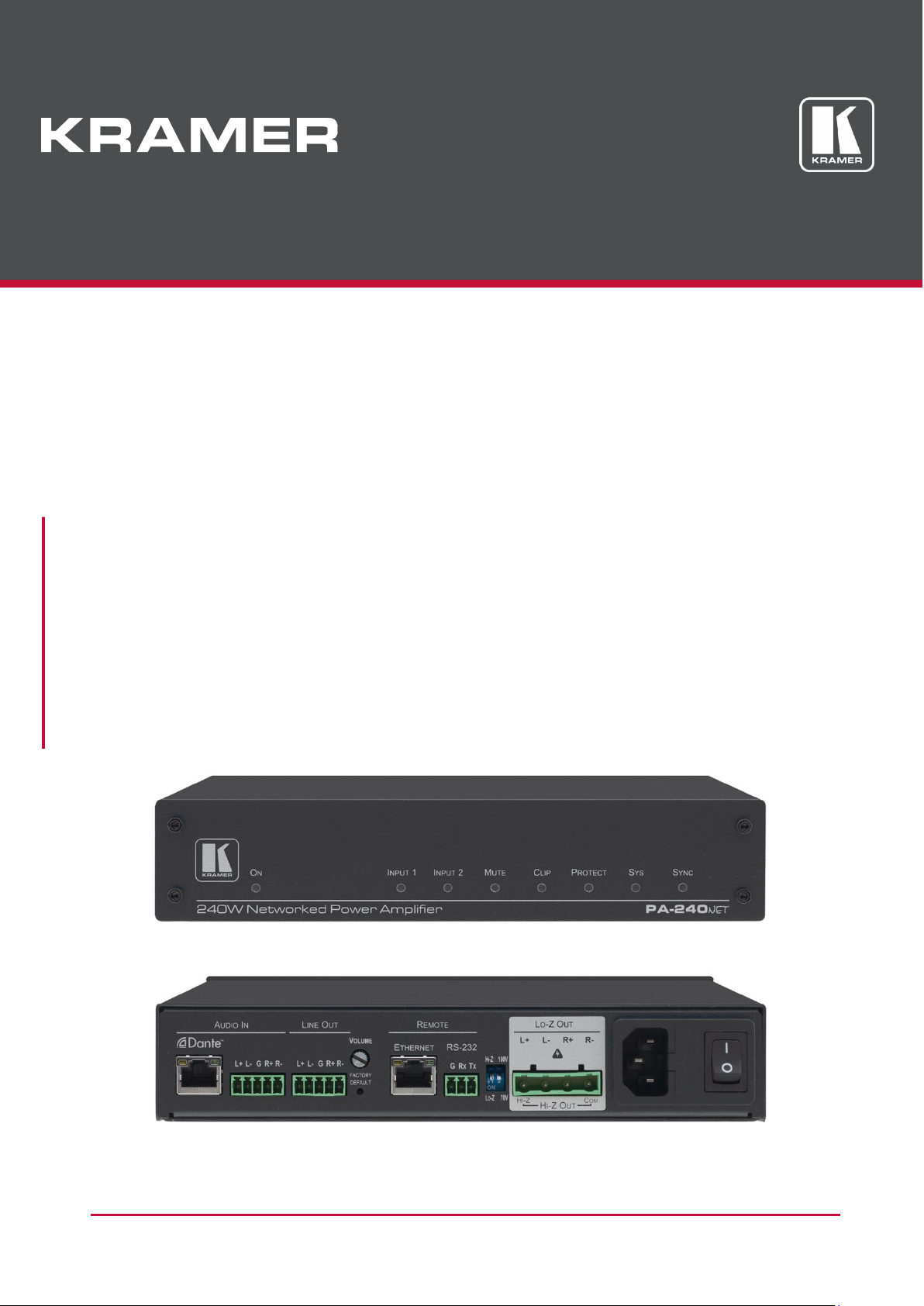
PA-240Net
240W Power Amplifier
PA-120Net
120W Power Amplifier
Page 2

PA-120Net, PA-240Net – Contents
i
Contents
Introduction 1
Getting Started 1
Overview 2
Typical Applications 3
Defining the PA-240Net and PA‑120Net Power Amplifier 4
Connecting the PA-240Net 6
Connecting the Output to a Balanced/Unbalanced Stereo Audio Acceptor 7
Connecting a Balanced/Unbalanced Stereo Audio Source to the Balanced Input 8
Connecting to PA-240Net via RS-232 8
RJ-45 Pinout 8
Connecting PA-240Net via the Ethernet Port 9
Operating the PA-240Net 11
Setting the DIP-Switches 11
Adjusting the Master Volume 11
Using the Embedded Web Pages 12
Setting the Speaker Output Parameters 13
Setting the Line Level Output Parameters 15
Selecting Hi-Z Mono Settings 16
Changing Standby Settings 16
Setting Device Parameters 17
Managing Web Page Security 19
Viewing the About Page 21
Using the Web-based Dante Controller 21
Technical Specifications 22
Default Communication Parameters 23
Protocol 3000 24
Understanding Protocol 3000 25
Kramer Protocol 3000 Syntax 26
Protocol 3000 Commands 27
Page 3

Kramer Electronics Ltd.
PA-120Net, PA-240Net – Introduction
1
Introduction
Welcome to Kramer Electronics! Since 1981, Kramer Electronics has been providing a world
of unique, creative, and affordable solutions to the vast range of problems that confront the
video, audio, presentation, and broadcasting professional on a daily basis. In recent years, we
have redesigned and upgraded most of our line, making the best even better!
Getting Started
We recommend that you:
• Unpack the equipment carefully and save the original box and packaging materials for
possible future shipment.
• Review the contents of this user manual.
Go to www.kramerav.com/downloads/PA-240Net or
www.kramerav.com/product/PA-120Net to check for up-to-date user manuals, application
programs, and to check if firmware upgrades are available (where appropriate).
Achieving the Best Performance
• Use only good quality connection cables (we recommend Kramer high-performance,
high-resolution cables) to avoid interference, deterioration in signal quality due to poor
matching, and elevated noise levels (often associated with low quality cables).
• Do not secure the cables in tight bundles or roll the slack into tight coils.
• Avoid interference from neighboring electrical appliances that may adversely influence
signal quality.
• Position your Kramer PA-240Net/PA-120Net away from moisture, excessive sunlight
and dust.
This equipment is to be used only inside a building. It may only be connected to other
equipment that is installed inside a building.
Safety Instructions
Caution: There are no operator serviceable parts inside the unit.
Warning: Use only the power cord that is supplied with the unit.
Warning: Do not open the unit. High voltages can cause electrical shock! Servicing by
qualified personnel only.
Warning: Disconnect the power and unplug the unit from the wall before installing.
Page 4

Kramer Electronics Ltd.
PA-120Net, PA-240Net – Introduction
2
Recycling Kramer Products
The Waste Electrical and Electronic Equipment (WEEE) Directive 2002/96/EC aims to reduce
the amount of WEEE sent for disposal to landfill or incineration by requiring it to be collected
and recycled. To comply with the WEEE Directive, Kramer Electronics made arrangements
with the European Advanced Recycling Network (EARN) and will cover any costs of
treatment, recycling and recovery of waste Kramer Electronics branded equipment on arrival
at the EARN facility. For details of Kramer’s recycling arrangements in your country, go to our
recycling pages at www.kramerav.com/support/recycling.
Overview
Congratulations on purchasing your Kramer PA-240Net 240W Power Amplifier and/or
PA-120Net 120W Power Amplifier.
Although this user manual describes the PA-240Net it refers to both PA-240Net and
PA-120Net, unless specified otherwise.
PA-240Net is a high-performance Hi-Z (70V/100V) and Lo-Z (4/8Ω), network controllable
power amplifier featuring balanced & unbalanced inputs, and a line-level balanced output.
This powerful amplifier is suitable for large-scale applications.
PA-240Net is housed in a desktop sized enclosure and can be setup using one of the
following methods:
• Mount the unit in a rack using the recommended rack adapter
(see www.kramerav.com/product/PA-120Net).
• Attach the rubber feet and place the unit on a flat surface.
PA-240Net provides exceptional quality and user-friendly operation.
PA-240Net features control via the Dante™ IP control matrix or Kramer Protocol 3000 via
RS-232 or USB connections
Exceptional Quality
• For PA-240Net:
▪ A single channel of 240W into a 70V/100V line.
▪ 2 channels of 120W into 4/8Ω.
• For PA-120Net:
▪ A single channel of 120W into a 70V/100V line.
▪ 2 channels of 60W into 4/8Ω.
• Individual input mix, EQ and HPF (High-Pass Filter) per output.
• Built-in 3-band parametric EQ.
Page 5

Kramer Electronics Ltd.
PA-120Net, PA-240Net – Introduction
3
User-friendly Operation
• Status LED indicators for the selected input, output muted and clipped signal on the
output.
• Over-current, short circuit or over-heat protection – The PROTECT LED lights and the
device shuts down until correct operational conditions are regained.
• Dante LED indicator for Dante network availability.
• Digital audio normal operation LED.
• Auto-standby with adjustable threshold.
• Controllable via RS-232 and IP.
Typical Applications
The PA-240Net is ideal for the following typical applications:
• Medium to large meeting rooms.
• Auditoriums and lecture halls.
• Court rooms.
• Retail stores and shopping centers.
• Hotel lobbies.
• Transportation hubs.
Page 6
Kramer Electronics Ltd.
PA-120Net, PA-240Net – Defining the PA-240Net and PA-120Net Power Amplifier
4
Defining the PA-240Net and
PA-120Net Power Amplifier
This section defines the PA-240Net.
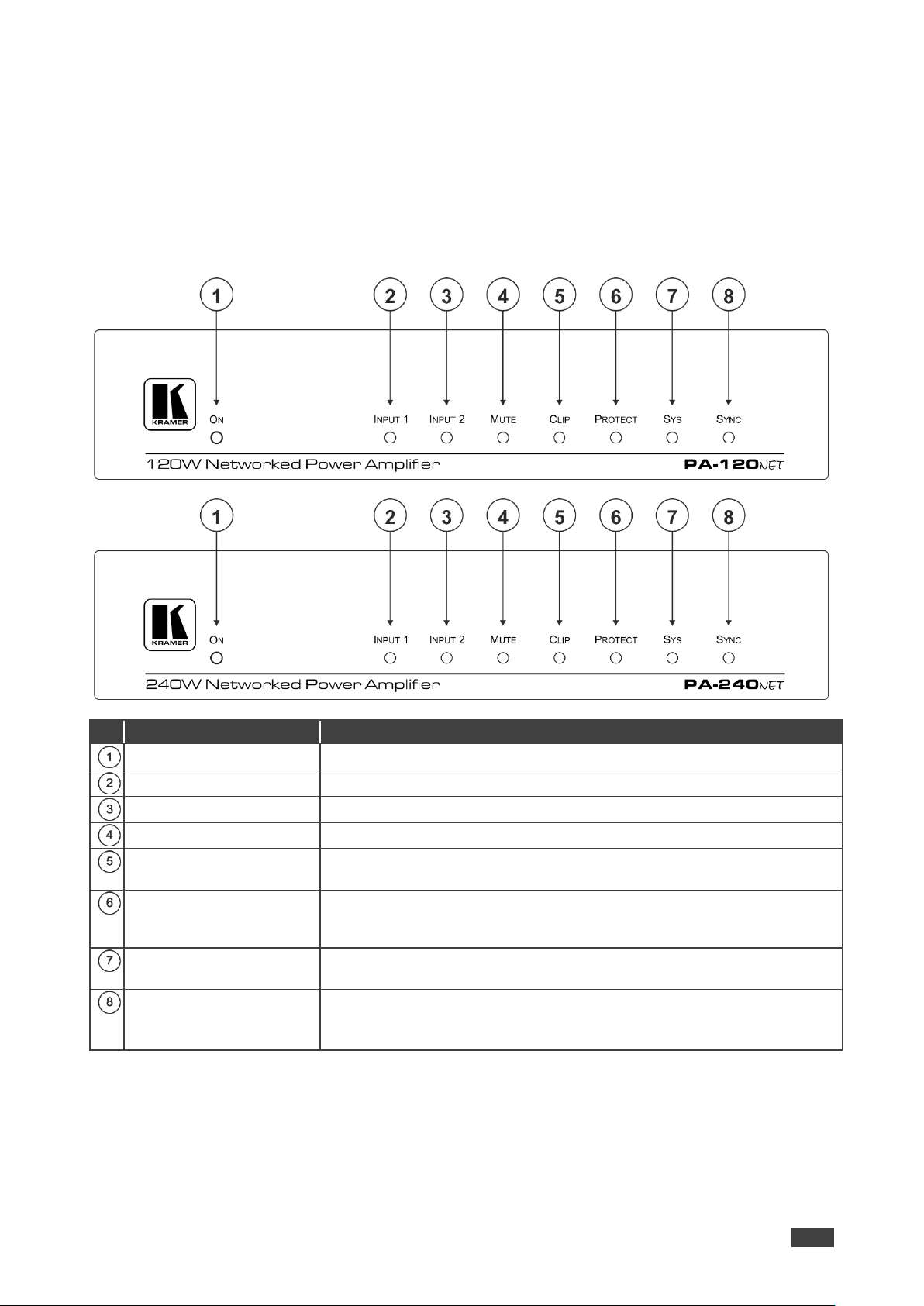
#
Feature
Function
ON LED
Lights green when powered on, orange when in standby.
INPUT 1 LED
Lights green when a signal is present on input 1.
INPUT 2 LED
Lights green when a signal is present on input 2.
MUTE
Lights red when the speaker output is muted, off when unmuted.
CLIP LED
Lights red when the signal is clipped on the output and creating distortion.
(When clipping is detected, lower the volume until the LED turns off.)
PROTECT LED
Lights red in case of over-current / short / over-heating.
The device powers down until operation conditions are corrected and
then powers up again.
SYS LED
Lights green when Dante network is available.
Lights red if an error has occurred.
SYNC LED
Lights green for digital audio normal operation.
Flashes green when this unit is the Master clock.
Lights red if an error has occurred.
Page 7
Kramer Electronics Ltd.
PA-120Net, PA-240Net – Defining the PA-240Net and PA-120Net Power Amplifier
5
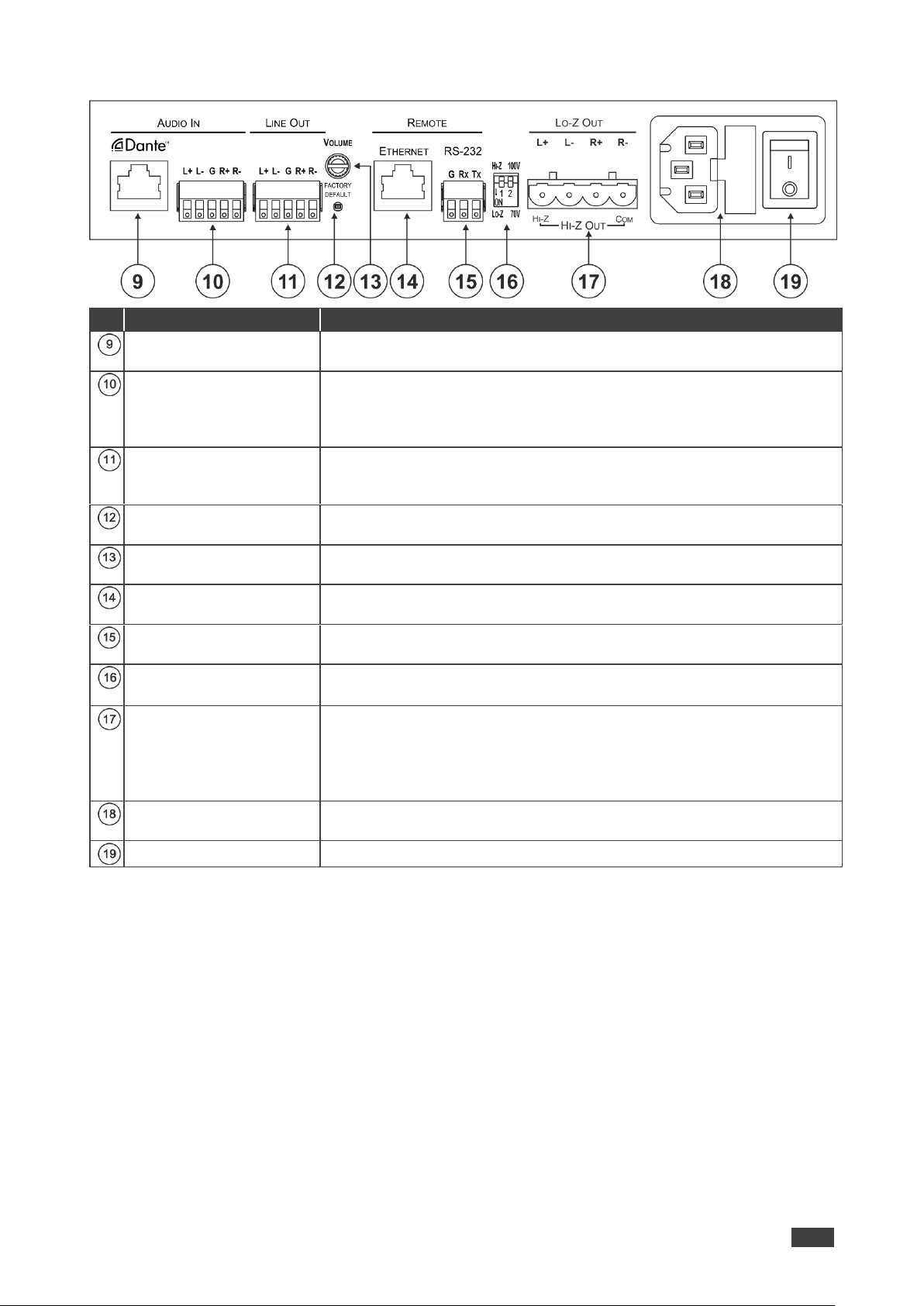
#
Feature
Function
Dante RJ-45 Port
Connect to the Dante™ audio source via the Network. By default, DHCP
is enabled.
AUDIO IN
Balanced/Unbalanced
Stereo Audio 5-pin
Terminal Block Connector
Connect to a line-level, balanced/unbalanced, stereo audio source.
LINE OUT Balanced
Stereo Audio 5-pin
Terminal Block Connector
Connect to a balanced, stereo audio acceptor (for example, amplified
speakers).
FACTORY DEFAULT
Button
Press to return to the factory default settings, including all the
configurations and network settings.
VOLUME Attenuator
Master volume for speaker output – rotate to set the maximum amplifier
volume.
ETHERNET RJ-45
Connector
Connect to an ETHERNET LAN to control the PA-240Net via built-in web
page. By default, IP is fixed at 192.168.1.39.
RS-232 (G, Tx, Rx) Port
Connect to an RS-232 connector on AV equipment or a PC or other
Serial Controller.
Hi-Z/Lo-Z and 100V/70V
DIP-Switches
DIP-Switch 1: Set to Hi-Z for high impedance or Lo-Z for low impedance.
DIP-Switch 2: In Hi-Z mode, select 70V or 100V operation.
Lo-Z and Hi-Z Speaker
Output Terminal Block
Connector
Lo-Z – Connect left +, left -, right +, and right - to Lo-Z (4Ω or 8Ω)
speakers.
Hi-Z – connect Hi-Z and COM to 70V or 100V Hi-Z speakers.
In Hi-Z mode, the output is mono and can be selected via webpage – Left
channel to mono, or stereo to mono summing
Power Connector with
Fuse
AC connector, enabling power supply to the unit.
Mains Power Switch
Switch for turning the device on or off.
Page 8

Kramer Electronics Ltd.
PA-120Net, PA-240Net – Connecting the PA-240Net
6
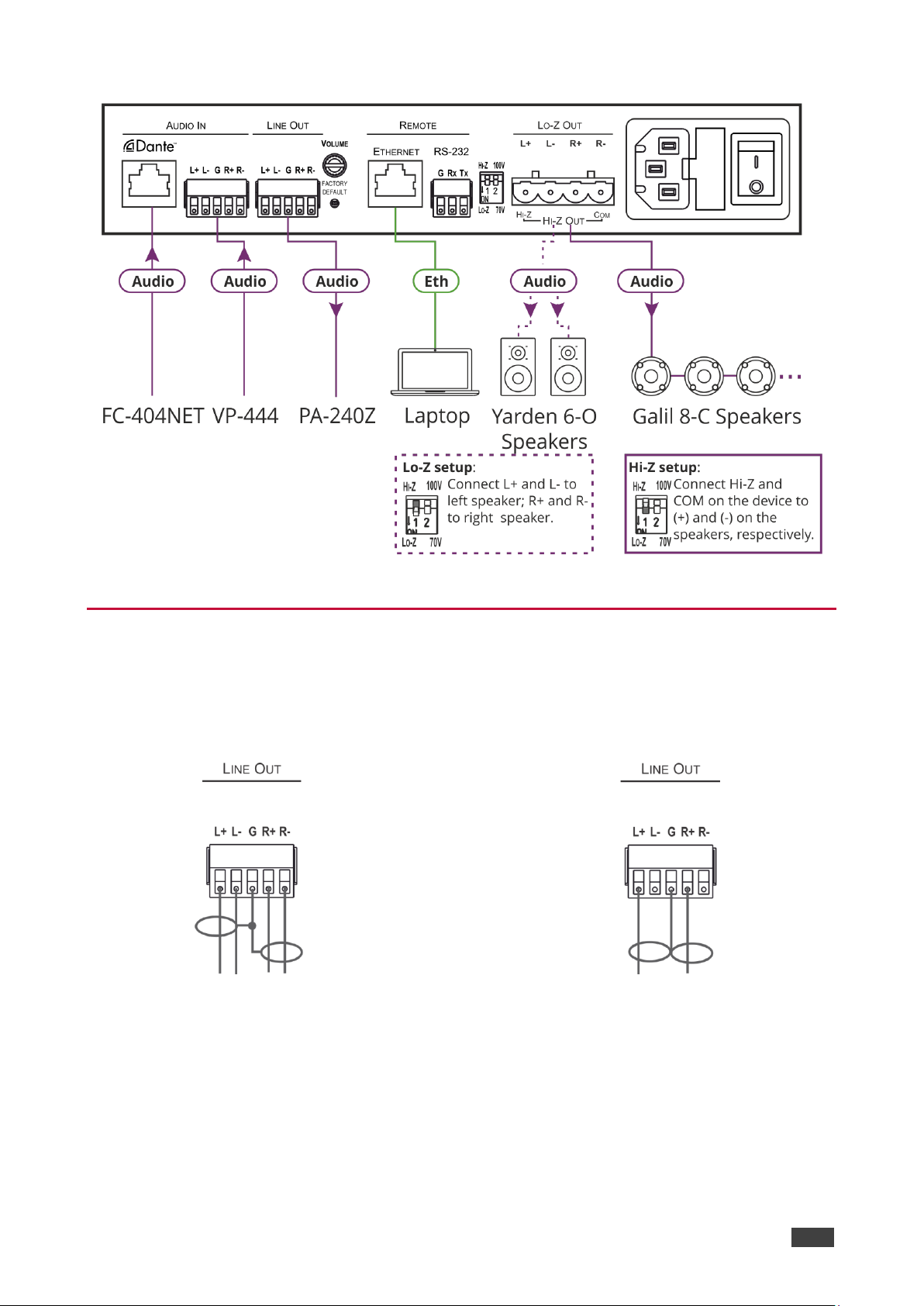
Connecting the PA-240Net
Always switch off the power to each device before connecting it to your PA-240Net. After
connecting your PA-240Net, connect its power and then switch on the power to each device.
To connect the PA-240Net as illustrated in the example in Figure 1:
1. Connect the balanced stereo audio source to the AUDIO IN 5-pin terminal block
connector (for example, a Kramer Switcher/Scaler).
2. Connect the LINE OUT balanced stereo audio 5-pin terminal block connecter to a
balanced stereo acceptor (for example, an additional PA-240Net device).
3. Connect the Hi-Z OUT or Lo-Z OUT 4-pin terminal block connector as follows:
▪ For Hi-Z connection: connect Hi-Z and COM terminal blocks to the + and – terminals
of a mono speaker (for example, the Galil 8-C ceiling speakers, daisy chained).
The speakers either output the left side (L+, L-) of the audio input or the stereo input
reduced to a mono signal (see Selecting Hi-Z Mono Settings on page 16).
▪ For Lo-Z connection: connect the L+ and L- connectors to the left-side speaker and
the R+ and R- connectors to the right-side.
4. Set the Hi-Z/Lo-Z and 100V/70V DIP-Switches :
▪ For Hi-Z operation: Set DIP-switch 1 to Hi-Z and then set DIP-switch 2 to 70V or
100V.
▪ For Lo-Z operation: Set DIP-switch 1 to Lo-Z.
5. Connect the Dante RJ-45 connector to any available IP network.
6. If required, connect:
▪ A PC via RS-232 , see Connecting to PA-240Net via RS-232 on page 8.
▪ The ETHERNET port , see Connecting PA-240Net via the Ethernet Port on
page 9.
7. Connect the power cord (not shown in Figure 1).
Page 9
Kramer Electronics Ltd.
PA-120Net, PA-240Net – Connecting the PA-240Net
7
Figure 1: Connecting to the PA-240Net Rear Panel
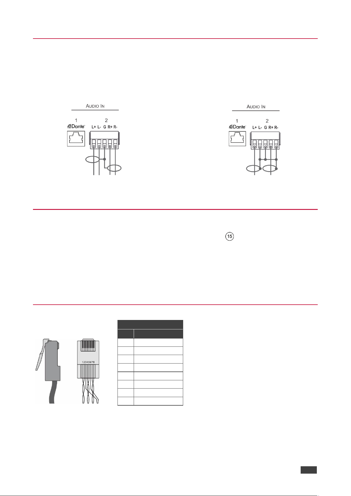
Connecting the Output to a Balanced/Unbalanced
Stereo Audio Acceptor
The following are the pinouts for connecting the output to a balanced or unbalanced stereo
audio acceptor:
Figure 2: Connecting the output to a balanced
stereo audio acceptor
Figure 3: Connecting the output to an unbalanced
stereo audio acceptor
Page 10
Kramer Electronics Ltd.
PA-120Net, PA-240Net – Connecting the PA-240Net
8
Connecting a Balanced/Unbalanced Stereo Audio
Source to the Balanced Input
The following are the pinouts for connecting a balanced or unbalanced stereo audio source to
the balanced input:
Figure 4: Connecting a balanced stereo audio
source to the balanced input
Figure 5: Connecting an unbalanced stereo audio
source to the balanced input
Connecting to PA-240Net via RS-232
You can connect to the PA-240Net via an RS-232 connection using, for example, a PC.
From the RS-232 9-pin D-sub serial port connect:
• Pin 2 to the TX pin on the PA-240Net RS-232 terminal block.
• Pin 3 to the RX pin on the PA-240Net RS-232 terminal block.
• Pin 5 to the G pin on the PA-240Net RS-232 terminal block.
RJ-45 Pinout
PIN EIA /TIA 568B
PIN
Wire Color
1
Orange / White
2
Orange
3
Green / White
4
Blue
5
Blue / White
6
Green
7
Brown / White
8
Brown
Page 11
Kramer Electronics Ltd.
PA-120Net, PA-240Net – Connecting the PA-240Net
9
Connecting PA-240Net via the Ethernet Port
You can connect to the PA-240Net via Ethernet using either of the following methods:
• Directly to the PC using a crossover cable (see Connecting the Ethernet Port Directly to
a PC on page 9).
• Via a network hub, switch, or router, using a straight-through cable (see Connecting the
Ethernet Port via a Network Hub or Switch on page 11).
If you want to connect via a router and your IT system is based on IPv6, speak to your IT
department for specific installation instructions.
Connecting the Ethernet Port Directly to a PC
You can connect the Ethernet port of the PA-240Net directly to the Ethernet port on your PC
using a crossover cable with RJ-45 connectors.
This type of connection is recommended for identifying the PA-240Net with the factory
configured default IP address
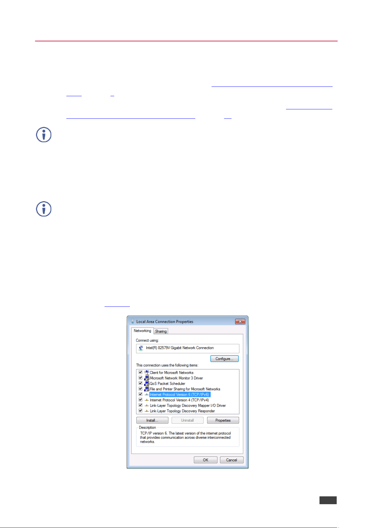
After connecting the PA-240Net to the Ethernet port, configure your PC as follows:
1. Click Start > Control Panel > Network and Sharing Center.
2. Click Change Adapter Settings.
3. Highlight the network adapter you want to use to connect to the device and click Change
settings of this connection.
The Local Area Connection Properties window for the selected network adapter appears
as shown in Figure 6.
Figure 6: Local Area Connection Properties Window
Page 12
Kramer Electronics Ltd.
PA-120Net, PA-240Net – Connecting the PA-240Net
10
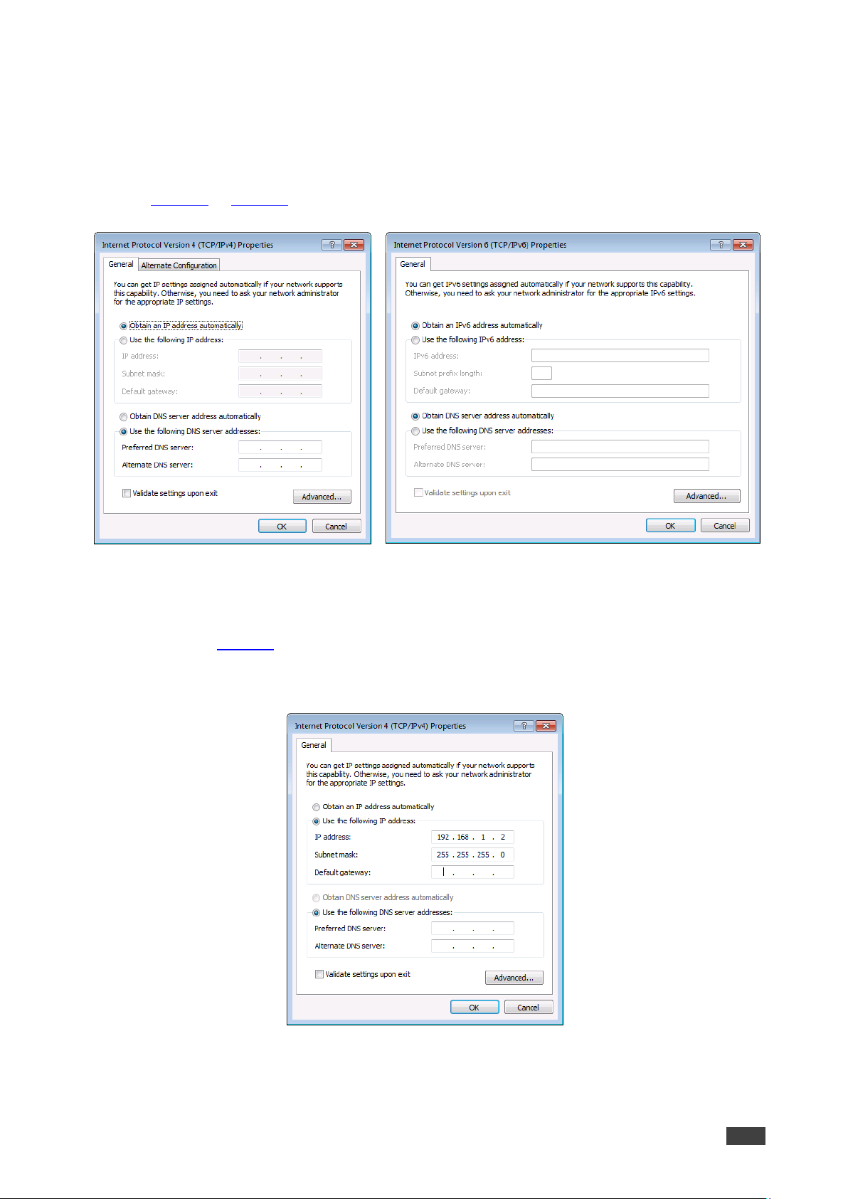
4. Highlight either Internet Protocol Version 6 (TCP/IPv6) or Internet Protocol Version 4
(TCP/IPv4) depending on the requirements of your IT system.
5. Click Properties.
The Internet Protocol Properties window relevant to your IT system appears as shown in
Figure 7 or Figure 8.
Figure 7: Internet Protocol Version 4
Properties Window
Figure 8: Internet Protocol Version 6
Properties Window
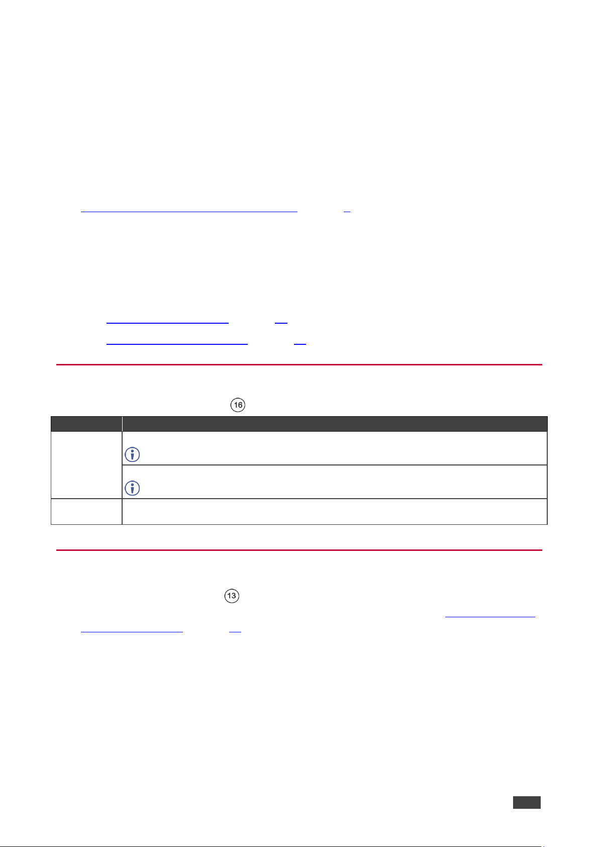
6. Select Use the following IP Address for static IP addressing and fill in the details as
shown in Figure 9.
For TCP/IPv4 you can use any IP address in the range 192.168.1.1 to 192.168.1.255
(excluding 192.168.1.39) that is provided by your IT department.
Figure 9: Internet Protocol Properties Window
7. Click OK.
8. Click Close.
Page 13
Kramer Electronics Ltd.
PA-120Net, PA-240Net – Operating the PA-240Net
11
Connecting the Ethernet Port via a Network Hub or Switch
You can connect the Ethernet port of the PA-240Net to the Ethernet port on a network hub or
using a straight-through cable with RJ-45 connectors.
Control Configuration via the Ethernet Port
To control several units via Ethernet, connect the Master unit (Device 1) via the Ethernet port
to the Ethernet port of your PC. Use your PC provide initial configuration of the settings (see
Connecting PA-240Net via the Ethernet Port on page 9).
Operating the PA-240Net
This section describes the following operations:
• Setting the DIP-Switches on page 11.
• Adjusting the Master Volume on page 11.
Setting the DIP-Switches
By default, the DIP-switches are set to Hi-Z and 100V.
DIP-Switch #
Setting
1
Set to Hi-Z (up) for high impedance configurations.
Use when connecting mono speakers in daisy-chain.
Set to Lo-Z (down) for low impedance configurations.
Use when connecting to a single pair of speakers, one to the left and one to the right.
2
When DIP-switch 1 is set to Hi-Z (up), set DIP-switch 2 either to 70V (down) or 100V (up),
according to your requirements.
Adjusting the Master Volume
Use the VOLUME attenuator on the rear panel to set the maximum level for the speaker
output. Adjust the master volume (speaker output) via the web pages, see Setting the Master
Volume and Balance on page 14.
Page 14

Kramer Electronics Ltd.
PA-120Net, PA-240Net – Using the Embedded Web Pages
12
Using the Embedded Web Pages
Control the PA-240Net via the web pages which are accessed using a Web browser and an
Ethernet connection.
Before attempting to connect:
• Perform the procedures described in Connecting PA-240Net via the Ethernet Port
on page 9.
• Ensure that your browser is supported.
The following operating systems and Web browsers are supported:
OS
Browser
Windows (7 and higher)
IE
FireFox
Chrome
Mac/iOS
Safari
Android
Chrome
The PA-240Net web pages enable performing the following:
• Setting the Speaker Output Parameters on page 13.
• Setting the Line Level Output Parameters on page 15.
• Selecting Hi-Z Mono Settings on page 16.
• Changing Standby Settings on page 16.
• Setting Device Parameters on page 17.
• Managing Web Page Security on page 19.
• Viewing the About Page on page 21.
• Using the Web-based Dante Controller on page 21.
To browse the PA-240Net web pages:
1. Open your Internet browser.
2. Type the IP address of the device in the address bar of your browser. For example, the
default IP address:
The Authentication window appears (if security is enabled).
Page 15

Kramer Electronics Ltd.
PA-120Net, PA-240Net – Using the Embedded Web Pages
13
3. Enter the User Name (Admin, by default) and Password (Admin, by default) and click
OK.
The Speaker Output page appears:
Figure 10: Speaker Output Page
4. Click the desired web page using the navigation list on the left or click the arrow at the
top to hide the navigation list.
Setting the Speaker Output Parameters
Use the Speaker Output page to set the speaker input signals mixing and the output
parameters.
PA-240Net can automatically set the line level output parameters according to the speaker
output parameters (see Setting the Line Level Output Parameters on page 15).
The Speaker Output Mixer enables performing the following operations:
• Mixing the Input Signal Levels on page 14.
• Setting Equalization Levels on page 14.
• Setting the Master Volume and Balance on page 14.
Page 16

Kramer Electronics Ltd.
PA-120Net, PA-240Net – Using the Embedded Web Pages
14
Mixing the Input Signal Levels
The indication buttons next to Input 1 and Input 2 appear green when there is an active signal
on that input.
To set the Mixing Level:
1. In the Navigation pane, click Speaker Output.
The Speaker Output page appears (see Figure 10).
2. In the Mix column, use the sliders to set the mixing level for each input or enter their
value below the sliders.
3. Set the High-Pass Filter ON or OFF to cut-off frequencies lower than 70Hz.
To save energy, enable the High-Pass Filter when outputting soft background music or
speech sources.
Setting Equalization Levels
We recommend that you first set the frequencies, then the Q and finally the Bass Mid and
Treble ranges.
To set EQ levels:
1. In the navigation pane click Speaker Output. The Speaker Output page appears.
2. In the EQ column set the following:
▪ Frequency: Bass [60Hz, 80Hz, 100Hz or 200Hz] Mid [500Hz, 1kHz, 1.5kHz or
2.5kHz] and Treble [10kHz, 12.5kHz, 15kHz or 17.5kHz] frequency.
▪ Q-Factor: Bass, Mid and Treble [0.1 to 16].
The lower the Q value, the wider the bandwidth.
▪ Equalization: Bass, Mid and Treble via the sliders or enter their value [dB] below the
sliders.
Setting the Master Volume and Balance
The maximum master volume level of the speaker output is set via the VOLUME attenuator
on the rear panel, see Adjusting the Master Volume on page 11.
In the Master Volume column:
• Use the slider to set the speaker audio level or enter the value [dB] below the slider.
• Click to mute/unmute the output volume.
• Set the left right balance on the speaker output.
Page 17

Kramer Electronics Ltd.
PA-120Net, PA-240Net – Using the Embedded Web Pages
15
Setting the Line Level Output Parameters
PA-240Net can automatically set the line level output parameters according to the speaker
output parameters (see Setting the Speaker Output Parameters on page 13), or they can be
set manually via the Line Level Output page.
To set the line level output parameters independently (unlinked to speaker output
parameters):
1. In the Navigation pane, click Speaker Output. The Speaker Output page appears.
2. Click Unlinked.
3. In the Navigation pane, click Line Level Output. The Line Level Output page appears.
Figure 11: Line Level Output Page
4. Set the line level parameters (see Setting the Speaker Output Parameters on page 13).
Page 18

Kramer Electronics Ltd.
PA-120Net, PA-240Net – Using the Embedded Web Pages
16
Selecting Hi-Z Mono Settings
To Select Hi-Z Mono Settings:
1. In the Navigation pane, click Audio Settings. The Audio Settings page appears.
Figure 12: Audio Settings Page
2. Set the Hi-Z reduction to mono to one of the following:
▪ Select Left only to use left audio in connectors.
▪ Select Stereo Down Mix to reduce the stereo input to mono.
Changing Standby Settings
To change standby settings:
1. In the Navigation pane, click Audio Settings.
The Audio Settings page appears (see Figure 12).
2. Define the Standby Settings:
▪ Set auto standby to ON or OFF.
▪ Type the audio threshold to initiate auto standby.
The "threshold" sets what is considered a valid input signal by the amplifier, and
what is considered noise.
This will also influence the front panel LEDs. If the input signal becomes lower
than the threshold, the LEDs will not illuminate.
▪ Set the standby timeout to 5, 10 or 15 minutes.
Page 19

Kramer Electronics Ltd.
PA-120Net, PA-240Net – Using the Embedded Web Pages
17
Setting Device Parameters
The Device Settings Web page shows the device details, such as name, MAC address and
firmware version. It also allows the following functions:
• Changing the name of the unit by typing the name in the Unit name text box.
• Changing the Ethernet Controller/Ethernet Dante Settings on page 17.
• Saving and Loading Settings on page 18.
• Performing a Factory Reset on page 18.
Changing the Ethernet Controller/Ethernet Dante Settings
To change the Ethernet settings, if required:
1. In the Navigation pane, click Device Settings. The Device Settings page appears:
Figure 13: Device Settings Page
Page 20

Kramer Electronics Ltd.
PA-120Net, PA-240Net – Using the Embedded Web Pages
18
2. Set DHCP to ON or OFF.
3. If DHCP is set to OFF, change any of the parameters (IP Address, Netmask and/or
Gateway).
4. Click Set.
• After changing the IP number, reload the web page with the new IP address.
• After changing the Subnet mask you need to restart the PA-240Net.
• If DHCP is checked, reload the web page with the new IP address.
5. Set the UDP and TCP port numbers and click Set.
Saving and Loading Settings
To save a configuration:
1. In the Navigation pane, click Device Settings.
The Device Settings page appears (see Figure 13).
2. Click Save. The following message appears:
“Configuration file is ready, right-click here to download”
3. Right-click the link (right-click here) and click Save link as.
The configuration is downloaded to your PC.
To load a configuration:
1. In the Navigation pane, click Device Settings.
The Device Settings page appears (see Figure 13).
2. Click Load and browse for the configuration file.
3. Click Open.
The configuration loads (this process may take a few minutes to complete)
A message indicating that the configuration uploaded successfully appears.
Performing a Factory Reset
To reset the device to its factory default values:
1. In the Navigation pane, click Device Settings.
The Device Settings page appears (see Figure 13).
2. Click Factory reset.
A confirmation warning message appears.
3. Click OK to start factory reset and follow the instructions on-screen.
Page 21

Kramer Electronics Ltd.
PA-120Net, PA-240Net – Using the Embedded Web Pages
19
Managing Web Page Security
Use the Authentication page to set Web access permission.
To access Web pages without using the password:
1. In the Navigation pane, click Security.
The Authentication page appears (see Figure 14).
Figure 14: Authentication Page
2. Set Activate Security to Disabled.
A message prompting for your password appears.
3. Type the current password (Admin by default) and click OK.
A message indicating that the password was changed successfully appears.
4. Click OK.
The Web page reloads and the web pages are unlocked .
Page 22

Kramer Electronics Ltd.
PA-120Net, PA-240Net – Using the Embedded Web Pages
20
To access Web pages using the password:
1. In the Navigation pane, click Security.
The Authentication page appears (see Figure 14).
2. Set Activate Security to Enabled for Web page password protection.
A confirmation warning message appears:
3. Click OK.
The connection is interrupted and authentication is required to access web pages.
Figure 15: Password Settings Page – Security Log In
4. Type the User Name (Admin, by default) and Password (Admin, by default).
5. Click Log In.
6. Select Security from the Navigation pane.
The Authentication page appears (see Figure 14).
7. Type the new authentication password twice in both New and Retype New text boxes.
8. Click Change.
A confirmation warning message appears.
9. Click OK. The following message appears.
A message indicating that the password was changed successfully appears.
10. Click OK.
The web pages are locked .
Page 23

Kramer Electronics Ltd.
PA-120Net, PA-240Net – Using the Embedded Web Pages
21
Viewing the About Page
The About page lets you view the web page version and Kramer Electronics Ltd details.
Using the Web-based Dante Controller
The PA-240Net can be operated using the Dante Controller, a Web-based software controller
application from Audinate. Use the controller to route audio and configure devices on a Dante
network. It features automatic device discovery, one-click signal routing and user-editable
device and channel labels as well as providing essential device status information and
powerful real-time network monitoring.
• Download the Dante Web-based Controller from:
www.audinate.com/products/software/dante-controller
• Download the Dante Web-based controller User Guide from:
https://dev.audinate.com/GA/dante-controller/userguide/pdf/latest
Page 24

Kramer Electronics Ltd.
PA-120Net, PA-240Net – Technical Specifications
22
Technical Specifications
PA-240Net
PA-120Net
Inputs
2 Channels, on a Dante™ Net
On an RJ-45 connector
1 Balanced Stereo Audio
+4dBu/10kΩ, on a 5-pin terminal block
Outputs
1 Balanced Stereo Audio
Line level, on a 5-pin terminal block
1 Speaker
On a 4-pin large terminal block
Ports
1 Control via IP
On an RJ-45 connector
1 RS-232
On a 3-pin terminal block
Amplifier
Input Sensitivity:
Full power @ 0.3V (–10dBV)
Output Power:
2 x 60W @ 4Ω or 8Ω
1 x 120W @ 70V or 100V
2 x 120W @ 4Ω or 8Ω
1 x 240W @ 70V or 100V
Class
D
Maximum Voltage Gain:
26dB SE / 32dB BTL
Dynamic Range
119dB
Frequency Response
20Hz to 20kHz @ +/-1dB
S/N Ratio:
80dB, 20Hz - 20kHz
Audio THD + Noise:
THD+N (1kHz @ 1W) 0.003 %
Audio 2nd Harmonic:
0.08% @ 75W RMS @ 4Ω 6.67kHz
Controls
Output volume attenuator, IP and RS-232
Power
Source:
Universal mains
operational voltage
85V AC – 265V AC
Universal mains
operational voltage
85V AC – 265V AC
(full power at 120V – 230V)
Consumption
195VA
265VA
Total System Efficiency
89%
90%
Environmental
Conditions
Operating Temperature
0° to +40°C (32° to 104°F)
Storage Temperature
-40° to +70°C (-40° to 158°F)
Humidity
10% to 90%, RHL non-condensing
Regulatory
Compliance
Safety
CE, FCC
Environmental
RoHs, WEEE
Enclosure
Size
Desktop
Type
Aluminum
Cooling
Fan ventilation
General
Net Dimensions (W, D, H)
21.5cm x 16.3cm x 4.4cm
(8.5" x 6.4" x 1.7")
Shipping Dimensions (W, D,
H)
40.5cm x 29.7cm x 9cm
(15.9" x 11.7" x 3.5")
Net Weight
1.05kg (2.3lbs)
Shipping Weight
1.65kg (3.6lbs) approx.
Included
Accessories
Power cord
Specifications are subject to change without notice at www.kramerav.com
Page 25

Kramer Electronics Ltd.
PA-120Net, PA-240Net – Technical Specifications
23
Default Communication Parameters
RS-232
Protocol 3000
Baud Rate:
115,200
Data Bits:
8
Stop Bits:
1
Parity:
None
Example (change the volume of
input 2 to -10 dB):
#AUD-LVL 1,2,-10
TCP/IP Parameters
Ethernet - Controller
Ethernet - Dante
IP Address:
192.168.1.39
DHCP
Subnet Mask:
255.255.000.000
N/A
Default Gateway:
192.168.0.1
N/A
Maximum UDP Connections:
Unlimited
N/A
Maximum TCP Connections:
Unlimited
N/A
UDP Port #:
50000
N/A
TCP Port #:
5000
N/A
Default Username / Password:
Admin / Admin
N/A
Full Factory Reset
Protocol 3000
Excluding ETH: use “#FACTORY” command and use
“#RESET” to restore the factory default values.
Page 26

Kramer Electronics Ltd.
PA-120Net, PA-240Net – Protocol 3000
24
Protocol 3000
The PA-240Net 240W Power Amplifier can be operated using the Kramer Protocol 3000
serial commands. The command framing varies according to how you interface with the
PA-240Net.
Generally, a basic video input switching command that routes a layer 1 video signal to HDMI
out 1 from HDMI input 2 (ROUTE 1,1,2), is entered as follows:
• Terminal communication software, such as Hercules:
The framing of the command varies according to the terminal communication software.
• K-Touch Builder (Kramer software):
• K-Config (Kramer configuration software):
All the examples provided in this section are based on using the K-Config software.
You can enter commands directly using terminal communication software (e.g., Hercules) by
connecting a PC to the serial or Ethernet port, depending on your device. To enter CR press
the Enter key (LF is also sent but is ignored by the command parser).
Commands sent from various non-Kramer controllers (e.g., Crestron) may require special
coding for some characters (such as, /X##). For more information, refer to your controller’s
documentation.
Page 27

Kramer Electronics Ltd.
PA-120Net, PA-240Net – Protocol 3000
25
For more information about Protocol 3000 commands, see:
• Understanding Protocol 3000 on page 25.
• Kramer Protocol 3000 Syntax on page 26.
• Protocol 3000 Commands on page 27.
Understanding Protocol 3000
Protocol 3000 commands are structured according to the following:
• Command – A sequence of ASCII letters (A-Z, a-z and -). A command and its
parameters must be separated by at least one space.
• Parameters – A sequence of alphanumeric ASCII characters (0-9, A-Z, a-z and some
special characters for specific commands). Parameters are separated by commas.
• Message string – Every command entered as part of a message string begins with a
message starting character and ends with a message closing character.
A string can contain more than one command. Commands are separated by a pipe (|)
character.
• Message starting character:
▪ # – For host command/query
▪ ~ – For device response
• Device address – K-NET Device ID followed by @ (optional, K-NET only)
• Query sign – ? follows some commands to define a query request
• Message closing character:
▪ CR – Carriage return for host messages (ASCII 13)
▪ CR LF – Carriage return for device messages (ASCII 13) and line-feed (ASCII 10)
• Command chain separator character – Multiple commands can be chained in the same
string. Each command is delimited by a pipe character (|). When chaining commands,
enter the message starting character and the message closing character only at the
beginning and end of the string.
Spaces between parameters or command terms are ignored. Commands in the string do
not execute until the closing character is entered. A separate response is sent for every
command in the chain.
Page 28

Kramer Electronics Ltd.
PA-120Net, PA-240Net – Protocol 3000
26
Kramer Protocol 3000 Syntax
The Kramer Protocol 3000 syntax uses the following delimiters:
• CR = Carriage return (ASCII 13 = 0x0D)
• LF = Line feed (ASCII 10 = 0x0A)
• SP = Space (ASCII 32 = 0x20)
Some commands have short name syntax in addition to long name syntax to enable faster
typing. The response is always in long syntax.
The Protocol 3000 syntax is in the following format:
• Host Message Format:
Start
Address
(optional)
Body
Delimiter
#
Device_id@
Message
CR
• Simple Command – Command string with only one command without addressing:
Start
Body
Delimiter
#
Command SP Parameter_1,Parameter_2,…
CR
• Command String – Formal syntax with command concatenation and addressing:
Start
Address
Body
Delimiter
#
Device_id@
Command_1 Parameter1_1,Parameter1_2,…|
Command_2 Parameter2_1,Parameter2_2,…|
Command_3 Parameter3_1,Parameter3_2,…|…
CR
• Device Message Format:
Start
Address
(optional)
Body
Delimiter
~
Device_id@
Message
CR LF
• Device Long Response – Echoing command:
Start
Address
(optional)
Body
Delimiter
~
Device_id@
Command SP [Param1 Param2 …] result
CR LF
Page 29

Kramer Electronics Ltd.
PA-120Net, PA-240Net – Protocol 3000
27
Protocol 3000 Commands
This section includes the following commands:
• System Commands on page 27.
• Audio Commands on page 31.
• Communication Commands on page 39.
System Commands
All devices running Protocol 3000 use these commands.
Command
Description
#
Protocol handshaking
BUILD-DATE?
Get device build date
FACTORY
Reset to factory default configuration
HELP
Get command list
MODEL?
Get device model
PROT-VER?
Get device protocol version
RESET
Reset device
SN?
Get device serial number
NAME
Set/get machine (DNS) name
#
Functions
Permission
Transparency
Set:
#
End User
Public
Get:
– – –
Description
Syntax
Set:
Protocol handshaking
#CR
Get:
–
–
Response
~nn@SP OK CR LF
Notes
Validates the Protocol 3000 connection and gets the machine number
Step-in master products use this command to identify the availability of a device
K-Config Example
“#”,0x0D
Page 30

Kramer Electronics Ltd.
PA-120Net, PA-240Net – Protocol 3000
28
BUILD-DATE?
Functions
Permission
Transparency
Set:
–
– – Get:
BUILD-DATE?
End User
Public
Description
Syntax
Set:
–
–
Get:
Get device build date
#BUILD-DATE?CR
Response
~nn@BUILD-DATE SP date SP timeCR LF
Parameters
date – Format: YYYY/MM/DD where YYYY = Year, MM = Month, DD = Day
time – Format: hh:mm:ss where hh = hours, mm = minutes, ss = seconds
K-Config Example
“#BUILD-DATE?”,0x0D
FACTORY
Functions
Permission
Transparency
Set:
FACTORY
End User
Public
Get:
–
–
–
Description
Syntax
Set:
Reset device to factory default configuration
#FACTORYCR
Get:
–
–
Response
~nn@FACTORY SP OKCR LF
Notes
This command deletes all user data from the device. The deletion can take some time.
Your device may require powering off and powering on for the changes to take effect.
K-Config Example
“#FACTORY”,0x0D
HELP
Functions
Permission
Transparency
Set:
–
– – Get:
HELP
End User
Public
Description
Syntax
Set:
–
–
Get:
Get command list or help for specific
command
2 options:
1. #HELPCR
2. #HELPSPcommand_name CR
Response
1. Multi-line: ~nn @Device available protocol 3000 commands:CR LF command,SPcommand… CR LF
To get help for command use: HELP (COMMAND_NAME)CR LF
2. Multi-line: ~nn @HELP SPcommand: CR LFdescriptionCR LFUSAGE:usageCR LF
Notes
To get help for a specific command use: HELPSPCOMMAND_NAMECR LF
K-Config Example
“#HELP”,0x0D
Page 31

Kramer Electronics Ltd.
PA-120Net, PA-240Net – Protocol 3000
29
MODEL?
Functions
Permission
Transparency
Set:
–
– – Get:
MODEL?
End User
Public
Description
Syntax
Set:
–
–
Get:
Get device model
#MODEL?CR
Response
~nn@MODEL SP model_nameCR LF
Parameters
model_name – string of up to 19 printable ASCII chars
Notes
This command identifies equipment connected to Step-in master products and notifies of identity changes
to the connected equipment. The Matrix saves this data in memory to answer REMOTE-INFO requests
K-Config Example
“#MODEL?”,0x0D
PROT-VER?
Functions
Permission
Transparency
Set:
–
–
–
Get:
PROT-VER?
End User
Public
Description
Syntax
Set:
–
–
Get:
Get device protocol version
#PROT-VER?CR
Response
~nn@PROT-VER SP 3000:version CR LF
Parameters
version – XX.XX where X is a decimal digit
K-Config Example
“#PROT-VER?”,0x0D
RESET
Functions
Permission
Transparency
Set:
RESET
Administrator
Public
Get:
–
–
–
Description
Syntax
Set:
Reset device
#RESETCR
Get:
–
–
Response
~nn@RESET SP OKCR LF
Notes
To avoid locking the port due to a USB bug in Windows, disconnect USB connections immediately after
running this command. If the port was locked, disconnect and reconnect the cable to reopen the port.
K-Config Example
“#RESET”,0x0D
Page 32

Kramer Electronics Ltd.
PA-120Net, PA-240Net – Protocol 3000
30
SN?
Functions
Permission
Transparency
Set:
–
–
–
Get:
SN?
End User
Public
Description
Syntax
Set:
–
–
Get:
Get device serial number
#SN?CR
Response
~nn@SN SP serial_numberCR LF
Parameters
serial_number – 14 decimal digits, factory assigned
K-Config Example
“#SN?”,0x0D
NAME
Functions
Permission
Transparency
Set:
NAME
Administrator
Public
Get:
NAME?
End User
Public
Description
Syntax
Set:
Set machine (DNS) name
#NAMESPmachine_name CR
Get:
Get machine (DNS) name
#NAME?CR
Response
Set: ~nn@NAME SP machine_name CR LF
Get: ~nn@NAME? SP machine_name CR LF
Parameters
machine_name – string of up to 15 alpha-numeric chars (can include hyphen, not at the beginning or end)
Notes
The machine name is not the same as the model name. The machine name is used to identify a specific
machine or a network in use (with DNS feature on)
K-Config Example
Set the DNS name of the device to “room-442”:
“#NAME room-442”,0x0D
Page 33

Kramer Electronics Ltd.
PA-120Net, PA-240Net – Protocol 3000
31
Audio Commands
These commands are used by audio devices running Protocol 3000.
Command
Description
AUD-CH-LINK
Set/get link between master configuration and slave/state
AUD-CLIP?
Get clipping status
AUD-FILTER
Set/get filter/state
AUD-HI-Z?
Get High Z status
AUD-IN-CONF
Set/get threshold and time
AUD-LVL
Set/get audio level in specific amplifier stage
AUD-MIX
Set/get mixer level
AUD-MONO-MODE
Set/get output select state when audio in HI-Z mode only
AUD-SIGNAL?
Get audio input signal status
AUD-STANDBY
Set/get standby mode/state
BALANCE
Set/get balance level
EQ-FREQ
Set/get equalizer center
EQ-LVL
Set/get equalization level
EQ-Q
Set/get Q level
MUTE
Set/get audio mute
AUD-CH-LINK
Functions
Permission
Transparency
Set:
AUD-CH-LINK
End User
Public
Get
AUD-CH-LINK?
End User
Public
Description
Syntax
Set:
Set link between master configuration and slave
#AUD-CH-LINKSP Ch1,Ch2,LinkState CR
Get:
Get the configuration link state
#AUD-CH-LINK?Ch1CR
Response
~nn@AUD-CH-LINK SP Ch1,Ch2,LinkStateCR LF
Parameters
Ch1 – 1 (Speaker Output)
Ch2 – 2 (Line Level Output)
LinkState – 1 (enable), 0 (disable)
Notes
Response if no link - AUD-CH-LINK 1,1,0
Response if link - AUD-CH-LINK 1,2,1
K-Config Example
Set a link between the speaker output configuration and the line level output configuration:
“#AUD-CH-LINK 1,2,1”,0x0D
Page 34

Kramer Electronics Ltd.
PA-120Net, PA-240Net – Protocol 3000
32
AUD-CLIP?
Functions
Permission
Transparency
Set:
–
– – Get
AUD-CLIP?
End User
Public
Description
Syntax
Set:
–
–
Get:
Get clipping status
#AUD-CLIP?SP Channel CR
Response
~nn@AUD-CLIP SP Channel,ClipStatus CR LF
Parameters
Channel – 1 (Speaker Output), 2 (Line Level Output)
ClipStatus – 1 (Clipping detected), 0 (Clipping not detected)
K-Config Example
Get the speaker output channel clipping status:
“#AUD-CLIP? 1”,0x0D
AUD-FILTER
Functions
Permission
Transparency
Set:
AUD-FILTER
End User
Public
Get
AUD-FILTER?
End User
Public
Description
Syntax
Set:
Set filter
#AUD-FILTERSP Channel,FilterType,Freq,State CR
Get:
Get filter state
#AUD-FILTER?SP Channel CR
Response
~nn@AUD-FILTER SP Channel,FilterType,Freq,State CR LF
Parameters
Channel – 1 (Speaker Output), 2 (Line Level Output)
FilterType – Filter type: 0 (High pass filter)
Freq – Filter frequency:
0 (T: 10kHz, M: 500Hz, B: 60Hz),
1 (T: 12.5kHz, M: 1kHz, B: 80Hz),
2 (T: 15kHz, M: 1.5kHz, B: 500Hz),
3 (T: 17.5kHz, M: 2.5kHz, B: 200Hz)
State – 1 (On), 0 (Off)
Notes
T=Treble, M=Middle, B=Bass
K-Config Example
Set the audio filter on the speaker output on to high-pass filter, T: 10kHz, M: 500Hz, B: 60Hz:
“#AUD-FILTER 1,0,0,1”,0x0D
Page 35

Kramer Electronics Ltd.
PA-120Net, PA-240Net – Protocol 3000
33
AUD-HI-Z
Functions
Permission
Transparency
Set:
–
– – Get
AUD-HI-Z?
End User
Public
Description
Syntax
Set:
–
–
Get:
Get High Z status
#AUD-HI-Z?CR
Response
~nn@AUD-HI-Z SP Channel,HiZState,HiZVolt CR LF
Parameters
Channel – 1 (Speaker Output), 2 (Line Level Output)
HiZState – 1 (Hi-Z state high), 0 (Hi-Z state low)
HiZVolt – Hi-Z volt level: 0 (70 Volt), 1 (100 Volt), 0xff (Ignore). Optional, active only in high state
Notes
Active only when state is high. Ignore everything else.
K-Config Example
Set the line level output to Hi-Z and 70V:
“#AUD-HI-Z 2,1,0”,0x0D
AUD-IN-CONF
Functions
Permission
Transparency
Set:
AUD-IN-CONF
End User
Public
Get
AUD-IN-CONF?
End User
Public
Description
Syntax
Set:
Set threshold and time to indicate
when signal is presents or not.
#AUD-IN-
CONFSPChannel,ThresholdDbLevel,TrigTimeDelay CR
Get:
Get threshold and time
#AUD-IN-CONF?CR Channel
Response
~nn@AUD-IN-CONF SP Channel,ThresholdDbLevel,TrigTimeDelay CR LF
Parameters
Channel – 1 (Speaker Output), 2 (Line Level Output)
ThresholdDbLevel – input level indicating when a signal is not present, range -100 to 0dB
TrigTimeDelay – 10 (fixed)
K-Config Example
Set the speaker output threshold level and time:
“#AUD-IN-CONF 1,-50,10”,0x0D
Page 36

Kramer Electronics Ltd.
PA-120Net, PA-240Net – Protocol 3000
34
AUD-LVL
Functions
Permission
Transparency
Set:
AUD-LVL
End User
Public
Get:
AUD-LVL?
End User
Public
Description
Syntax
Set:
Set volume level
#AUD-LVLSP stage,channel,volume,mutebehavior CR
Get:
Get volume level
#AUD-LVL?SP stage,channel CR
Response
~nn@AUD-LVL SP stage,channel,volume CR LF
Parameters
stage – 1 (For output processing)
channel – 1 (Speaker Output), 2 (Line Level Output)
volume – volume level -80db to 10dB
mutebehavior – optional, 1 (changing the volume does not affect the mute state)
K-Config Example
Set the speaker output audio level t0 -50dB:
“#AUD-LVL 1,1,-50”,0x0D
AUD-MIX
Functions
Permission
Transparency
Set:
AUD-MIX
End User
Public
Get:
AUD-MIX?
End User
Public
Description
Syntax
Set:
Set mixer level
#AUD-MIXSP channel,knob,level CR
Get:
Get mixer level
#AUD-MIX?SP channel,knob CR
Response
~nn@AUD-MIX SP channel,knob,levelCR LF
Parameters
channel – 1 (Speaker Output), 2 (Line Level Output)
knob – mixer knob number: 1 (Input 1), 2 (Input 2)
level – mixer level: -80 to 10dB
K-Config Example
Set the input mixing level of input 2 on the speaker output to -48dB:
“#AUD-MIX 1,2,-48”,0x0D
Page 37

Kramer Electronics Ltd.
PA-120Net, PA-240Net – Protocol 3000
35
AUD-MONO-MODE
Functions
Permission
Transparency
Set:
AUD-MONO-MODE
End User
Public
Get
AUD-MONO-MODE?
End User
Public
Description
Syntax
Set:
Set output select state when audio in HI-Z mode only
#AUD-MONO-MODESP MonoMode CR
Get:
Get output select state when audio in HI-Z mode only
#AUD-MONO-MODE?CR
Response
~nn@AUD-MONO-MODE SP MonoMode CR LF
Parameters
MonoMode – The mono output mode:
0 (output is ”stereo mix to mono” – both left and right mix to one channel),
1 (output is “left to mono” – duplicate left channel information to the right and play both)
Notes
These commands are active only when the state is HI-Z, otherwise an error is returned.
To set, the MonoMode parameter must be used.
K-Config Example
Set the output to mix to mono:
“#AUD-MONO-MODE 0”,0x0D
AUD-SIGNAL
Functions
Permission
Transparency
Set:
–
– – Get
AUD-SIGNAL?
End User
Public
Description
Syntax
Set:
–
–
Get:
Get audio input signal status
#AUD-SIGNAL?SP inp_id CR
Response
~nn@AUD-SIGNAL SP inp_id,status CR LF
Parameters
Inp_id – input number: 1 (Input 1), 2 (Input 2)
status – 0 (OFF, no signal), 1 (ON, signal present)
Response Triggers
After execution, response is sent to the com port from which the Get was received
Response is sent to all com ports if audio status state was changed on any input
K-Config Example
get the status of input 1:
“#AUD-SIGNAL? 1”,0x0D
Page 38

Kramer Electronics Ltd.
PA-120Net, PA-240Net – Protocol 3000
36
AUD-STANDBY
Functions
Permission
Transparency
Set:
AUD-STANDBY
End User
Public
Get
AUD-STANDBY?
End User
Public
Description
Syntax
Set:
Set standby mode
#AUD-STANDBYSP StandbyMode,TimeDelay CR
Get:
Get standby mode state
#AUD-STANDBY?CR
Response
~nn@AUD-STANDBY SP StandbyMode,TimeDelay CR LF
Parameters
StandbyMode – 0 (Off), 1 (Delayed, auto mode), 2 (Standby mode)
TimeDelay – 5, 10, or 15 (time delay [min] to standby mode)
Notes
Active only in auto mode
K-Config Example
Set the standby delay time to 10 minutes:
“#AUD-STANDBY 1,10”,0x0D
BALANCE
Functions
Permission
Transparency
Set:
BALANCE
End User
Public
Get:
BALANCE?
End User
Public
Description
Syntax
Set:
Set balance level
#BALANCESPchannel,balancelevel CR
Get:
Get balance level
#BALANCE?SPchannel CR
Response
~nn@BALANCE SP channel,balance_levelCR LF
Parameters
channel – 1 (Speaker output), 2 (Line level output)
balancelevel – -15 to +15 (audio parameter in Kramer units, minus sign precedes negative values)
++ increase current value
-- decrease current value
K-Config Example
Set the speaker output balance to +12:
“#BALANCE 1,12”,0x0D
Page 39

Kramer Electronics Ltd.
PA-120Net, PA-240Net – Protocol 3000
37
EQ-FREQ
Functions
Permission
Transparency
Set:
EQ-FREQ
End User
Public
Get
EQ-FREQ?
End User
Public
Description
Syntax
Set:
Set equalizer frequency
#EQ- FREQSP Stage,Channel,EqType,EqFreq CR
Get:
Get equalizer frequency
#EQ- FREQ?SP Stage,Channel,EqType CR
Response
~nn@EQ- FREQ SP Stage,Channel,EqType,EqFreq CR LF
Parameters
Stage – 1 (Output)
Channel – 1 (Speaker output), 2 (Line Level Output)
EqType – 0 (Bass), 1 (Middle), 2 (Treble)
EqFreq –
0 (T: 10kHz, M: 500Hz, B: 60Hz),
1 (T: 12.5kHz, M: 1kHz, B: 80Hz),
2 (T: 15kHz, M: 1.5kHz, B: 500Hz),
3 (T: 17.5kHz, M: 2.5kHz, B: 200Hz)
Notes
T=Treble, M=Middle, B=Bass
K-Config Example
Set speaker output equalizer frequency on the bass to 200Hz:
“#EQ-FREQ 1,1,0,3”,0x0D
EQ-LVL
Functions
Permission
Transparency
Set:
EQ-LVL
End User
Public
Get:
EQ-LVL?
End User
Public
Description
Syntax
Set:
Set equalization level
#EQ-LVLSP Stage,Channel,EqType,Level CR
Get :
Get equalization level
#EQ-LVL?SP Stage,Channel,EqType CR
Response
~nn@EQ-LVL SP Stage,Channel,EqType,Level CR LF
Parameters
Stage – 1 (Output processing)
Channel – 1 (Speaker output), 2 (Line level output)
EqType – 0 (Bass), 1 (Middle), 2 (Treble)
Level –equalizer level
K-Config Example
Set Bass EQ level of the speaker output to 12:
“#EQ-LVL 1,1,0,12”,0x0D
Page 40

Kramer Electronics Ltd.
PA-120Net, PA-240Net – Protocol 3000
38
EQ-Q
Functions
Permission
Transparency
Set:
EQ-Q
End User
Public
Get
EQ-Q?
End User
Public
Description
Syntax
Set:
Set Q level
#EQ-QSP Channel,EqType,Q_level CR
Get:
Get Q level
#EQ-Q?SP Channel,EqType CR
Response
~nn@EQ-Q SP Channel,EqType,Q_level CR LF
Parameters
Channel – 1 (Speaker output), 2 (Line level output)
EqType – 0 (Bass), 1 (Middle), 2 (Treble)
Q_level – 0 to 15 (Q level)
K-Config Example
Set the line level output treble Q level to 8:
“#EQ-Q 1,2,8 4”,0x0D
MUTE
Functions
Permission
Transparency
Set:
MUTE
End User
Public
Get:
MUTE?
End User
Public
Description
Syntax
Set:
Set audio mute
#MUTESPchannel,mute_mode CR
Get:
Get audio mute
#MUTE?SPchannel CR
Response
~nn@MUTE SP channel,mute_mode CR LF
Parameters
channel – 1 (Speaker output), 2 (Line level output)
mute_mode – 0 (Off), 1 (On)
K-Config Example
Set speaker output to mute:
“#MUTE 1,1”,0x0D
Page 41

Kramer Electronics Ltd.
PA-120Net, PA-240Net – Protocol 3000
39
Communication Commands
These commands are used by network devices running Protocol 3000.
Command
Description
NET-CONFIG
Set/get a network configuration
ETH-PORT
Set/get Ethernet port protocol
NET-DHCP
Set/get DHCP mode
NET-MAC?
Get MAC address
NET-CONFIG
Functions
Permission
Transparency
Set:
NET-CONFIG
End User
Public
Get:
NET-CONFIG?
End User
Public
Description
Syntax
Set:
Set a network configuration.
#NET-CONFIGSP id,ip,net_mask,gatewayCR LF
Get:
Get a network configuration.
#NET-CONFIG?SP id CR LF
Response
Get: ~nn@NET-CONFIG SP id,ip,net_mask,gateway CR LF
Parameters
id – network ID
ip – network IP
net_mask – network mask
gateway – network gateway
K-Config Example
“#NET-CONFIG 1,192.168.113.10,255.255.0.0,192.168.0.1”,0x0D
ETH-PORT
Functions
Permission
Transparency
Set:
ETH-PORT
Administrator
Public
Get:
ETH-PORT?
End User
Public
Description
Syntax
Set:
Set Ethernet port protocol
#ETH-PORTSP portType,ETHPort CR
Get:
Get Ethernet port protocol
#ETH-PORT?SP portType CR
Response
~nn@ETH-PORT SP portType,ETHPort CR LF
Parameters
portType – 0 (TCP), 1 (UDP)
ETHPort – 0-65534 (TCP / UDP port number)
Notes
If the port number you enter is already in use, an error is returned.
The port number must be within the following range: 2000-(2^16-1).
UDP port 50001 and TCP port 5001 are reserved for internal use.
K-Config Example
Set the Ethernet port protocol for TCP to port 12457:
“#ETH-PORT 0,12457”,0x0D
Page 42

Kramer Electronics Ltd.
PA-120Net, PA-240Net – Protocol 3000
40
NET-DHCP
Functions
Permission
Transparency
Set:
NET-DHCP
Administrator
Public
Get:
NET-DHCP?
End User
Public
Description
Syntax
Set:
Set DHCP mode
#NET-DHCPSP mode CR
Get:
Get DHCP mode
#NET-DHCP?CR
Response
~nn@NET-DHCP SP modeCR LF
Parameters
mode –
0 (do not use DHCP. Use the IP address set by the factory or the NET-IP command),
1 (try to use DHCP. If unavailable, use the IP address set by the factory or the NET-IP command)
Notes
Connecting Ethernet to devices with DHCP may take more time in some networks
To connect with a randomly assigned IP by DHCP, specify the device DNS name (if available) using the
command “NAME”. You can also get an assigned IP by direct connection to USB or RS-232 protocol port if
available
For proper settings consult your network administrator
K-Config Example
Enable DHCP mode, if available:
“#NET-DHCP 1”,0x0D
NET-MAC?
Functions
Permission
Transparency
Set:
–
–
–
Get:
NET-MAC?
End User
Public
Description
Syntax
Set:
–
–
Get:
Get MAC address
#NET-MAC?CR
Response
~nn@NET-MAC SP mac_address CR LF
Parameters
mac_address – Unique MAC address. Format: XX-XX-XX-XX-XX-XX where X is hex digit
K-Config Example
“#NET-MAC?”,0x0D
Page 43

The warranty obligations of Kramer Electronics Inc. (“Kramer Electronics”) for this product are limited to the terms set forth below:
What is Covered
This limited warranty covers defects in materials and workmanship in this product.
What is Not Covered
This limited warranty does not cover any damage, deterioration or malfunction resulting from any alteration, modification, improper or unreasonable use
or maintenance, misuse, abuse, accident, neglect, exposure to excess moisture, fire, improper packing and shipping (such claims must be presented to
the carrier), lightning, power surges, or other acts of nature. This limited warranty does not cover any damage, deterioration or malfunction resulting
from the installation or removal of this product from any installation, any unauthorized tampering with this product, any repairs attempted by anyone
unauthorized by Kramer Electronics to make such repairs, or any other cause which does not relate directly to a defect in materials and/or workmanship
of this product. This limited warranty does not cover cartons, equipment enclosures, cables or accessories used in conjunction with this product.
Without limiting any other exclusion herein, Kramer Electronics does not warrant that the product covered hereby, including, without limitation, the
technology and/or integrated circuit(s) included in the product, will not become obsolete or that such items are or will remain compatible with any other
product or technology with which the product may be used.
How Long this Coverage Lasts
The standard limited warranty for Kramer products is seven (7) years from the date of original purchase, with the following exceptions:
1. All Kramer VIA hardware products are covered by a standard three (3) year warranty for the VIA hardware and a standard three (3) year
warranty for firmware and software updates.
2. All Kramer fiber optic cables, adapter-size fiber optic extenders, active cables, cable retractors, all Kramer speakers and Kramer touch panels
are covered by a standard one (1) year warranty.
3. All Kramer Cobra products, all Kramer Calibre products, all Kramer Minicom digital signage products, all HighSecLabs products, all
streaming, and all wireless products are covered by a standard three (3) year warranty.
4. All Sierra Video MultiViewers are covered by a standard five (5) year warranty.
5. Sierra switchers & control panels are covered by a standard seven (7) year warranty (excluding power supplies and fans that are covered for
three (3) years).
6. K-Touch software is covered by a standard one (1) year warranty for software updates.
7. All Kramer passive cables are covered by a ten (10) year warranty.
Who is Covered
Only the original purchaser of this product is covered under this limited warranty. This limited warranty is not transferable to subsequent purchasers or
owners of this product.
What Kramer Electronics Will Do
Kramer Electronics will, at its sole option, provide one of the following three remedies to whatever extent it shall deem necessary to satisfy a proper
claim under this limited warranty:
1. Elect to repair or facilitate the repair of any defective parts within a reasonable period of time, free of any charge for the necessary parts and
labor to complete the repair and restore this product to its proper operating condition. Kramer Electronics will also pay the shipping costs
necessary to return this product once the repair is complete.
2. Replace this product with a direct replacement or with a similar product deemed by Kramer Electronics to perform substantially the same
function as the original product.
3. Issue a refund of the original purchase price less depreciation to be determined based on the age of the product at the time remedy is sought
under this limited warranty.
What Kramer Electronics Will Not Do Under This Limited Warranty
If this product is returned to Kramer Electronics or the authorized dealer from which it was purchased or any other party authorized to repair Kramer
Electronics products, this product must be insured during shipment, with the insurance and shipping charges prepaid by you. If this product is returned
uninsured, you assume all risks of loss or damage during shipment. Kramer Electronics will not be responsible for any costs related to the removal or reinstallation of this product from or into any installation. Kramer Electronics will not be responsible for any costs related to any setting up this product, any
adjustment of user controls or any programming required for a specific installation of this product.
How to Obtain a Remedy Under This Limited Warranty
To obtain a remedy under this limited warranty, you must contact either the authorized Kramer Electronics reseller from whom you purchased this
product or the Kramer Electronics office nearest you. For a list of authorized Kramer Electronics resellers and/or Kramer Electronics authorized service
providers, visit our web site at www.kramerav.com or contact the Kramer Electronics office nearest you.
In order to pursue any remedy under this limited warranty, you must possess an original, dated receipt as proof of purchase from an authorized Kramer
Electronics reseller. If this product is returned under this limited warranty, a return authorization number, obtained from Kramer Electronics, will be
required (RMA number). You may also be directed to an authorized reseller or a person authorized by Kramer Electronics to repair the product.
If it is decided that this product should be returned directly to Kramer Electronics, this product should be properly packed, preferably in the original
carton, for shipping. Cartons not bearing a return authorization number will be refused.
Limitation of Liability
THE MAXIMUM LIABILITY OF KRAMER ELECTRONICS UNDER THIS LIMITED WARRANTY SHALL NOT EXCEED THE ACTUAL PURCHASE PRICE PAID
FOR THE PRODUCT. TO THE MAXIMUM EXTENT PERMITTED BY LAW, KRAMER ELECTRONICS IS NOT RESPONSIBLE FOR DIRECT, SPECIAL,
INCIDENTAL OR CONSEQUENTIAL DAMAGES RESULTING FROM ANY BREACH OF WARRANTY OR CONDITION, OR UNDER ANY OTHER LEGAL
THEORY. Some countries, districts or states do not allow the exclusion or limitation of relief, special, incidental, consequential or indirect damages, or
the limitation of liability to specified amounts, so the above limitations or exclusions may not apply to you.
Exclusive Remedy
TO THE MAXIMUM EXTENT PERMITTED BY LAW, THIS LIMITED WARRANTY AND THE REMEDIES SET FORTH ABOVE ARE EXCLUSIVE AND IN LIEU OF
ALL OTHER WARRANTIES, REMEDIES AND CONDITIONS, WHETHER ORAL OR WRITTEN, EXPRESS OR IMPLIED. TO THE MAXIMUM EXTENT
PERMITTED BY LAW, KRAMER ELECTRONICS SPECIFICALLY DISCLAIMS ANY AND ALL IMPLIED WARRANTIES, INCLUDING, WITHOUT LIMITATION,
WARRANTIES OF MERCHANTABILITY AND FITNESS FOR A PARTICULAR PURPOSE. IF KRAMER ELECTRONICS CANNOT LAWFULLY DISCLAIM OR
EXCLUDE IMPLIED WARRANTIES UNDER APPLICABLE LAW, THEN ALL IMPLIED WARRANTIES COVERING THIS PRODUCT, INCLUDING WARRANTIES
OF MERCHANTABILITY AND FITNESS FOR A PARTICULAR PURPOSE, SHALL APPLY TO THIS PRODUCT AS PROVIDED UNDER APPLICABLE LAW.
IF ANY PRODUCT TO WHICH THIS LIMITED WARRANTY APPLIES IS A “CONSUMER PRODUCT” UNDER THE MAGNUSON -MOSS WARRANTY ACT (15
U.S.C.A. §2301, ET SEQ.) OR OTHER APPLICABLE LAW, THE FOREGOING DISCLAIMER OF IMPLIED WARRANTIES SHALL NOT APPLY TO YOU, AND
ALL IMPLIED WARRANTIES ON THIS PRODUCT, INCLUDING WARRANTIES OF MERCHANTABILITY AND FITNESS FOR THE PARTICULAR PURPOSE,
SHALL APPLY AS PROVIDED UNDER APPLICABLE LAW.
Other Conditions
This limited warranty gives you specific legal rights, and you may have other rights which vary from country to country or state to state.
This limited warranty is void if (i) the label bearing the serial number of this product has been removed or defaced, (ii) the product is not distributed by
Kramer Electronics or (iii) this product is not purchased from an authorized Kramer Electronics reseller. If you are unsure whether a reseller is an
authorized Kramer Electronics reseller, visit our web site at www.kramerav.com or contact a Kramer Electronics office from the list at the end of this
document.
Your rights under this limited warranty are not diminished if you do not complete and return the product registration form or complete and submit the
online product registration form. Kramer Electronics thanks you for purchasing a Kramer Electronics product. We hope it will give you years of
satisfaction.
Page 44

www.KramerAV.com
info@KramerAV.com
P/N:
2900-301040
Rev:
2
SAFETY WARNING
Disconnect the unit from the power supply before opening and servicing
For the latest information on our products and a list of Kramer distributors, visit our Web site where
updates to this user manual may be found.
We welcome your questions, comments, and feedback.
 Loading...