

Page 1

MV-6 Quick Start
P/N:
2900- 301278QS
Rev:
2
Scan for full manual
MV-6 Quick Start Guide
This guide helps you install and use your MV-6 for the first time.
Go to www.kramerav.com/downloads/MV-6 to download the latest user manual and check if firmware
upgrades are available.
Step 1: Check what’s in the box
MV-6 3G HD-SDI Multiviewer
1 Set of rack ears
4 Rubber feet
Remote control transmitter with batteries
1 Power cord
1 Quick start guide
Step 2: Get to know your MV-6
Front Panel
#
Feature
Function
1
LCD Video Preview Screen
Displays the output signal.
2
WINDOW Buttons (A to F)
Press to select one of the windows displayed on the screen.
3
INPUT Buttons (1 to 6)
Press to select the active input after selecting one of the windows displayed on the screen.
4
LCD Character Display
During normal operation, displays the Window/Input list. During menu operation, displays the
menu options.
5
Menu Navigation Buttons
Press to navigate the menu options.
6
ENTER Button
Press to select a menu or accept a parameter/value.
7
PANEL LOCK Button
Press and hold to disable/enable the front panel buttons.
8
LAYOUT 6 Input Button
Press to display all six inputs in the window configuration shown on the button.
9
LAYOUT 4 Input Button
Press to display four selected inputs in the window configuration shown on the button.
10
LAYOUT Full Screen Button
Press to display one selected input as a full screen.
11
LAYOUT 2 Input Button
Press to display two selected inputs in the window configuration shown on the button.
12
U1 Button
Press to select the first user-defined output window configuration (see Step 6).
13
U2 Button
Press to select the second user-defined output window configuration (see Step 6).
14
FREEZE Button
Press to freeze the selected output window.
15
POSITION Buttons
Press either the H (horizontal) or V (vertical) button to change the position of the active
window (see Step 6).
16
SIZE Buttons
Press either the H (width) or V (height) button to change the size of the active window (see
Step 6).
17
MENU Button
Press to move back one level through the menu.
Page 2
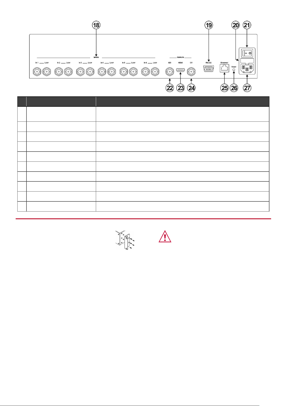
Rear Panel
#
Feature
Function
18
INPUTS (1 to 6) and Associated
BNC LOOP Outputs (1 to 6)
Connect inputs to video sources and loop outputs to loop video acceptors.
19
RS-232 9-pin D-sub (F) Connector
Connect to the serial port on a PC or remote control.
20
Mains Power Fuse
Fuse for protecting the device.
21
Mains Power Switch
Switch for turning the device ON or OFF.
22
OUTPUTS SDI BNC Connector
Connect to an SDI video acceptor.
23
OUTPUTS HDMI Connector
Connect to an HDMI video acceptor.
24
OUTPUTS CV BNC Connector
Connect to a composite video acceptor.
25
ETHERNET RJ-45 Connector
Connect to a PC via a LAN for remote control.
26
RESET Button
Press and hold while power cycling the device to reset to factory default configuration.
27
Mains Power Connector
Connect to the mains power.
Step 3: Mount MV-6
To rack mount the machine, attach both rack ears
(by removing the screws from each side of the
machine and replacing those screws through the
rack ears) or place the machine on a table.
• Ensure that the environment (e.g., maximum ambient temperature &
air flow) is compatible for the device.
• Avoid uneven mechanical loading.
• Appropriate consideration of equipment nameplate ratings should be
used for avoiding overloading of the circuits.
• Reliable earthing of rack-mounted equipment should be maintained.
Page 3

Step 4: Connect inputs and outputs
Always switch OFF the power on each device before connecting it to your MV-6.
RS-232 Connection:
Use a 9-wire straight cable and connect only pin 2 to pin 2, pin 3 to pin 3, and pin 5 to pin 5 to the RS-232 9-pin D-sub port on
your PC.
A null-modem adapter/connection is not required.
Step 5: Connect power
Connect the power cord to MV-6 and plug it into the mains electricity.
Safety Instructions (See www.kramerav.com for updated safety information)
Caution:
• For products with relay terminals and GPI\O ports, please refer to the permitted rating for an external connection, located next to the
terminal or in the User Manual.
• There are no operator serviceable parts inside the unit.
Warning:
• Use only the power cord that is supplied with the unit.
• Disconnect the power and unplug the unit from the wall before installing.
• Do not open the unit. High voltages can cause electrical shock! Servicing by qualified personnel only.
• To ensure continuous risk protection, replace fuses only according to the rating specified on the product label which located on the
bottom of the unit.
Step 6: Operate MV-6
Kramer MV-6 Controller Software:
RS-232 and Ethernet:
RS-232
Protocol 3000
Baud Rate:
115200
Data Bits:
8
Stop Bits:
1
Parity:
None
Command Format:
ASCII
Example (Output 1 to Input 2):
#V 2>1CR
Default Ethernet Parameters
IP Address:
192.168.1.39
Subnet mask:
255.255.255.0
Default gateway:
192.168.1.1
UDP Port #50000:
50000
TCP Port #5000:
5000
Maximum UDP Ports:
10
Maximum TCP Ports:
4
To achieve specified extension distances, use the recommended Kramer cables available at www.kramerav.com/product/MV-6.
Using third-party cables may cause damage!
Page 4

Viewing the Window/Input Display:
When MV-6 is powered on, the unit performs a self-test and then, the display shows the letters of each output window and,
underneath each letter, the input that corresponds to that window:
WIN A B C D E F
INP 2 4 5 6 1 3
During operation, if there is no button activity for approximately 60 seconds the display reverts to the Window/Input display.
Adjusting the Size of an Output Window:
1. Press the relevant WINDOW button.
The selected button lights.
2. Press either the H Size or V Size button to adjust the width or height of the selected window.
3. Use the left (◄) and right (►) buttons to adjust the window width and use the up (▲) and down button (▼) to adjust
the window height.
4. Press MENU twice to exit the window size setting.
Adjusting the Position of a Window:
1. Select the required window by pressing the relevant WINDOW button.
The selected button lights.
2. Press either the H POSITION or V POSITION button to move the window.
3. Use the left (◄) and right (►) buttons to move the window horizontally and use the up (▲) and down button (▼) to
move the window vertically.
4. Press MENU twice to exit the window position setting.
Defining and Saving a Custom Window Layout:
1. Adjust the windows to the required configuration.
2. Press and hold either the U1 or U2 LAYOUT button until the button flashes once.
The window layout is stored in the relevant memory.
Loading a Window Layout:
Press one of the four predefined LAYOUT buttons or one of the two user-defined LAYOUT buttons (U1 or U2) to load a
window layout onto the screen.
The selected button flashes three times and the relevant window layout is displayed on the screen.
 Loading...