


KRAMER ELECTRONICS LTD.
USER MANUAL
MODEL:
MV-6
3G HD-SDI Multiviewer
P/N: 2900-000737 Rev 8

MV-6 – Contents
i
Contents
1 Introduction 1
2 Getting Started 2
2.1 Achieving the Best Performance 2
2.2 Safety Instructions 3
2.3 Recycling Kramer Products 3
3 Overview 4
3.1 Accessory to Medical Equipment (IEC 60601-1) 5
3.2 Defining the MV-6 3G HD-SDI Multiviewer 5
4 Installing in a Rack 9
5 Connecting the MV-6 10
5.1 Connecting to the RS-232 Port 11
5.2 Connecting via Ethernet 12
6 Operating the MV-6 Locally 16
6.1 Using the Display 16
6.2 Adjusting the Size of a Window 16
6.3 Adjusting the Position of a Window 17
6.4 Defining and Saving a Custom Window Layout 17
6.5 Recalling a Window Layout 18
6.6 Freezing/Releasing a Video Output 18
6.7 Locking the Front Panel 18
6.8 Resetting the Device to Factory Defaults 19
6.9 Using the Menu 19
7 Operating the MV-6 Remotely 23
7.1 Operating the MV-6 via the RS-232 Serial Port 23
7.2 MV-6 Controller Software 23
7.3 The Menu Bar 25
7.4 Upgrading the Firmware 36
8 Technical Specifications 37
9 Default Communication Parameters 38
10 Kramer Protocol 3000 Syntax 39
10.1 Host Message Format 39
10.2 Device Message Format 39
10.3 Command Terms 40
10.4 Entering Commands 41
10.5 Bidirectional Definition 41
10.6 Command Chaining 41
10.7 Maximum String Length 42
10.8 Backward Support 42
11 Protocol 3000 Commands 43
11.1 System Commands - Mandatory 43
11.2 System Commands 48
11.3 Video Commands 52
11.4 Multiviewer Commands 55
11.5 Communication Commands 61
12 Parameters 65
12.1 On/Off 65
12.2 Color Space 65
12.3 Genlock Types 65

ii
MV-6 - Contents
12.4 Stage 65
12.5 Video Resolutions 65
12.6 Custom Resolution Parameters 67
12.7 View Modes 67
12.8 Font Size 68
Figures
Figure 1: MV-6 3G HD-SDI Multiviewer Front Panel 6
Figure 2: MV-6 3G HD-SDI Multiviewer Rear Panel 8
Figure 3: Connecting the MV-6 3G HD-SDI Multiviewer 11
Figure 4: Local Area Connection Properties Window 13
Figure 5: Internet Protocol Version 4 Properties Window 13
Figure 6: Internet Protocol Version 6 Properties Window 14
Figure 7: Internet Protocol Properties Window 14
Figure 8: MV-6 Controller Software Main Window 24
Figure 9: Quick Access Toolbar 26
Figure 10: Connect Window 27
Figure 11: Windows Position 28
Figure 12: Switch Buttons 29
Figure 13: Layer Order 30
Figure 14: Switching an Input to a Window 31
Figure 15: Windows Setup Window 32
Figure 16: Input Button Properties Window 33
Figure 17: Device Details Window 34
Figure 18: About MV-6 Window 36

MV-6 - Introduction
1
1 Introduction
Welcome to Kramer Electronics! Since 1981, Kramer Electronics has been
providing a world of unique, creative, and affordable solutions to the vast range of
problems that confront video, audio, presentation, and broadcasting professionals
on a daily basis. In recent years, we have redesigned and upgraded most of our
line, making the best even better!
Our 1,000-plus different models now appear in 14 groups that are clearly defined
by function: GROUP 1: Distribution Amplifiers; GROUP 2: Switchers and Routers;
GROUP 3: Control Systems; GROUP 4: Format/Standards Converters; GROUP 5:
Range Extenders and Repeaters; GROUP 6: Specialty AV Products; GROUP 7:
Scan Converters and Scalers; GROUP 8: Cables and Connectors; GROUP 9:
Room Connectivity; GROUP 10: Accessories and Rack Adapters; GROUP 11:
Sierra Video Products; GROUP 12: Digital Signage; GROUP 13: Audio; and
GROUP 14: Collaboration.
Congratulations on purchasing your Kramer MV-6 3G HD-SDI Multiviewer, which
is ideal for the following typical applications:
Professional broadcasting and production studios
Presentation applications
3G HD-SDI multi-viewing for medical equipment

2
MV-6 - Getting Started
2 Getting Started
We recommend that you:
Unpack the equipment carefully and save the original box and packaging
materials for possible future shipment
Review the contents of this user manual
Go to http://www.kramerelectronics.com/support/product_downloads.asp
to check for up-to-date user manuals, application programs, and to check if
firmware upgrades are available (where appropriate).
2.1 Achieving the Best Performance
To achieve the best performance:
Use only good quality connection cables (we recommend Kramer high-
performance, high-resolution cables) to avoid interference, deterioration in
signal quality due to poor matching, and elevated noise levels (often
associated with low quality cables)
Do not secure the cables in tight bundles or roll the slack into tight coils
Avoid interference from neighboring electrical appliances that may adversely
influence signal quality
Position your Kramer MV-6 away from moisture, excessive sunlight and dust
This equipment is to be used only inside a building. It may only be
connected to other equipment that is installed inside a building.
i
!

MV-6 - Getting Started
3
2.2 Safety Instructions
Caution:
There are no operator serviceable parts inside the unit
Warning:
Use only the power cord that is supplied with the unit
Warning:
Do not open the unit. High voltages can cause
electrical shock! Servicing by qualified personnel only
Warning:
Disconnect the power and unplug the unit from the wall
before installing
2.3 Recycling Kramer Products
The Waste Electrical and Electronic Equipment (WEEE) Directive 2002/96/EC
aims to reduce the amount of WEEE sent for disposal to landfill or incineration by
requiring it to be collected and recycled. To comply with the WEEE Directive,
Kramer Electronics has made arrangements with the European Advanced
Recycling Network (EARN) and will cover any costs of treatment, recycling and
recovery of waste Kramer Electronics branded equipment on arrival at the EARN
facility. For details of Kramer’s recycling arrangements in your particular country
go to our recycling pages at http://www.kramerelectronics.com/support/recycling/.
!

4
MV-6 - Overview
3 Overview
The MV-6 is a versatile, high-performance video viewer for signals up to 3G
HD-SDI. The device can window up to six sources in any layout and output the
image in SDI, HDMI and CV formats. Both preprogrammed and customizable
screen division is supported.
In particular, the MV-6 features:
Input bandwidth of up to 3Gbps which supports standard definition, high
definition and 3G high definition serial digital video signals (SD/HD/3G
HD-SDI)
Standard Definition (SD) means an NTSC or PAL compatible video format consisting of
480 (for NTSC) or 576 (for PAL) lines of interlaced video.
High Definition (HD) means a video format consisting of 720 active lines of progressive
video or 1080 lines of progressive or interlaced video.
SMPTE 259M, 292M and 424M input compliance and support for data rates
of 270Mbps, 1483.5Mbps, 1485Mbps, 2967Mbps and 2970Mbps
Input cable equalization up to 350m (1150ft) for SD signals, 140m for
1.5GHz HD signals, and 120m (394ft) for 3GHz HD signals
Multi-video output formats; HD-SDI (292M) and 3G HD-SDI (SMPTE 424M),
HDMI and composite
Front panel color LCD preview screen for real-time display of output
Kramer re-Klocking™ and equalization on each input – rebuilds the digital
signal to travel longer distances
Flexible control options; front panel with menu LCD and on-screen displays,
Ethernet, and RS-232
Screen handling buttons; freeze, size, position, and four pre-programmed
and two user-definable layouts
Medical equipment compliance

MV-6 - Overview
5
The MV-6 is housed in a 2U height enclosure and is fed from a 100-240 VAC
universal switching power supply. The device can be controlled via the front panel
buttons and remotely via:
RS-232 serial commands transmitted by a PC, touch-screen system or other
serial controller
Ethernet over a LAN
3.1 Accessory to Medical Equipment (IEC 60601-1)
In the modern medical environment remote access is essential, for example, to
transfer clinical data between doctors and to train to medical students. The MV-6
is certified according to the IEC 60601-1-2, Clause 2.1.3, Medical Electrical
Equipment, Part 1: General Requirements for EMC standard which is required
when accessory devices are used at locations where medical personnel and
patients are present.
The MV-6 constitutes an optional component that can be considered necessary
and suitable as part of medical equipment or for use as part of a medical system to
provide real time simultaneous video feeds to those present at the local medical
environment and at remote locations. In this environment, the MV-6 can be added
to the system ONLY if the connecting equipment has been evaluated and meets
the IEC 60601-1-2 EMC standards. Note, that when attaching accessory devices
to a digital or analog interface, they must comply with the IEC standard for which
they are used: EMC Standard (IEC 60601-1-2), Information Technology equipment
(IEC 60950-1 (2ed)).
3.2 Defining the MV-6 3G HD-SDI Multiviewer
This section defines the MV-6.
6
MV-6 - Overview
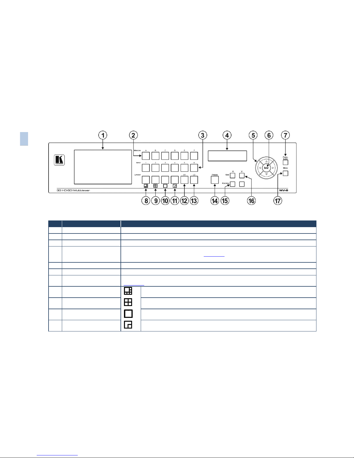
Figure 1: MV-6 3G HD-SDI Multiviewer Front Panel
#
Feature
Function
1
LCD Video Preview Screen
LCD screen to display the output signal
2
WINDOW Buttons (A to F)
Press to select one of the windows
3
INPUT Buttons (1 to 6)
Press to select the active input following selection of an active window (using the WINDOW buttons)
4
LCD Menu 2 Line x 16
Character Window/Input or
Menu Display
During normal operation the Window/Input list is displayed. During menu operations, the
Menu/parameter/values are displayed (see Section 6.9)
5
Menu Navigation Buttons
Press the up (▲), down (▼), left (◄) and right (►) buttons to navigate the menu, parameters or values
6
ENTER Button
Press to enter the menu or accept the parameter/value
7
PANEL LOCK Button
Press and hold to lock the front panel buttons. Press and hold again to unlock the buttons (see
Section 6.7)
8
Screen Layout Button
(6 windows)
Press to display and output all six inputs as per the pattern
9
Screen Layout Button
(4 windows)
Press to display and output four selected inputs in a quad pattern
10
Screen Layout Button
(full screen)
Press to display and output one selected input as a full screen
11
Screen Layout Button
(2 windows)
Press to display and output two selected inputs as per the pattern
6
MV-6 – Overview

MV-6 - Overview
7
MV-6 – Overview
7
12
U1 Button
Press to select the first user-definable output window pattern (programmed using the menu, see
Section 7.3)
13
U2 Button
Press to select the second user-definable output window pattern (programmed using the menu, see
Section 7.3)
14
FREEZE Button
Press to freeze the selected video window (see Section 6.6)
15
POSITION Buttons
Press either the horizontal (H) or vertical (V) button to change the position of the active window (see
Section 6.3)
SIZE Buttons
Press either the width (H) or height (V) button to change the size of the active window (see
Section 6.9)
17
MENU Button
Press to move back one level through the menu (see Section 6.9)

8
MV-6 - Overview
Figure 2: MV-6 3G HD-SDI Multiviewer Rear Panel
#
Feature
Function
18
INPUTS (1 to 6) and Associated BNC
LOOP Outputs (1 to 6)
Connect Inputs to video sources and Loop outputs to loop video acceptors (see
Section 5)
19
RS-232 9-pin D-sub (F) Connector
Connect to the serial port on a PC or remote controller (see Section 5.1)
20
Mains Power Fuse
Fuse for protecting the device
21
Mains Power Switch
Switch for turning the device on or off
22
OUTPUTS SDI BNC Connector
Connect to an SDI video acceptor (see Section 6.9)
23
OUTPUTS HDMI Connector
Connect to an HDMI video acceptor
24
OUTPUTS CV BNC Connector
Connect to a composite video acceptor
25
ETHERNET RJ-45 Connector
Connect to a PC via a LAN for remote control (see Section 5.2)
26
RESET Button
Press and hold while power cycling the device to reset to factory default configuration
(see Section 6.8)
27
Mains Power Connector
Connect to the mains power
8
MV-6 – Overview
MV-6 - Installing in a Rack
9
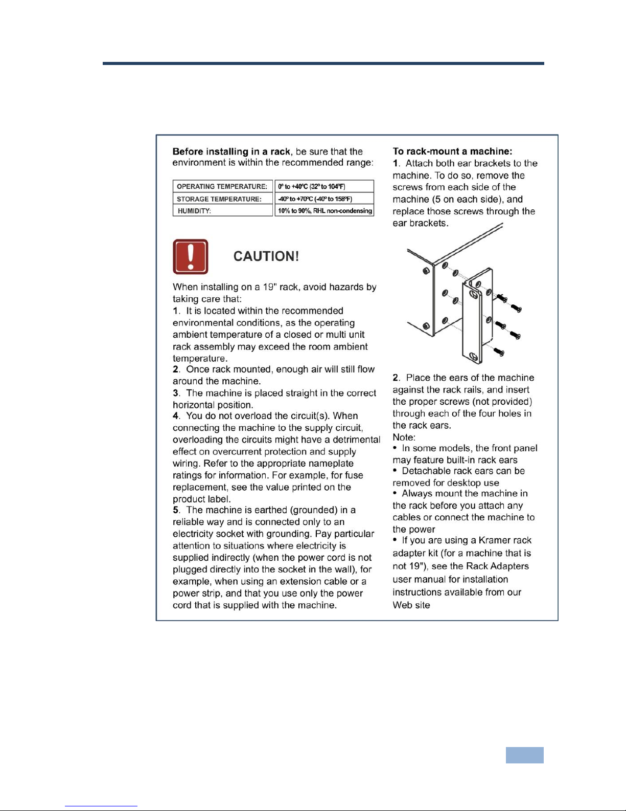
4 Installing in a Rack
This section provides instructions for rack mounting the unit.

10
MV-6 - Connecting the MV-6
5 Connecting the MV-6
Always switch off the power to each device before connecting it to your
MV-6. After connecting your MV-6, connect its power and then switch
on the power to each device.
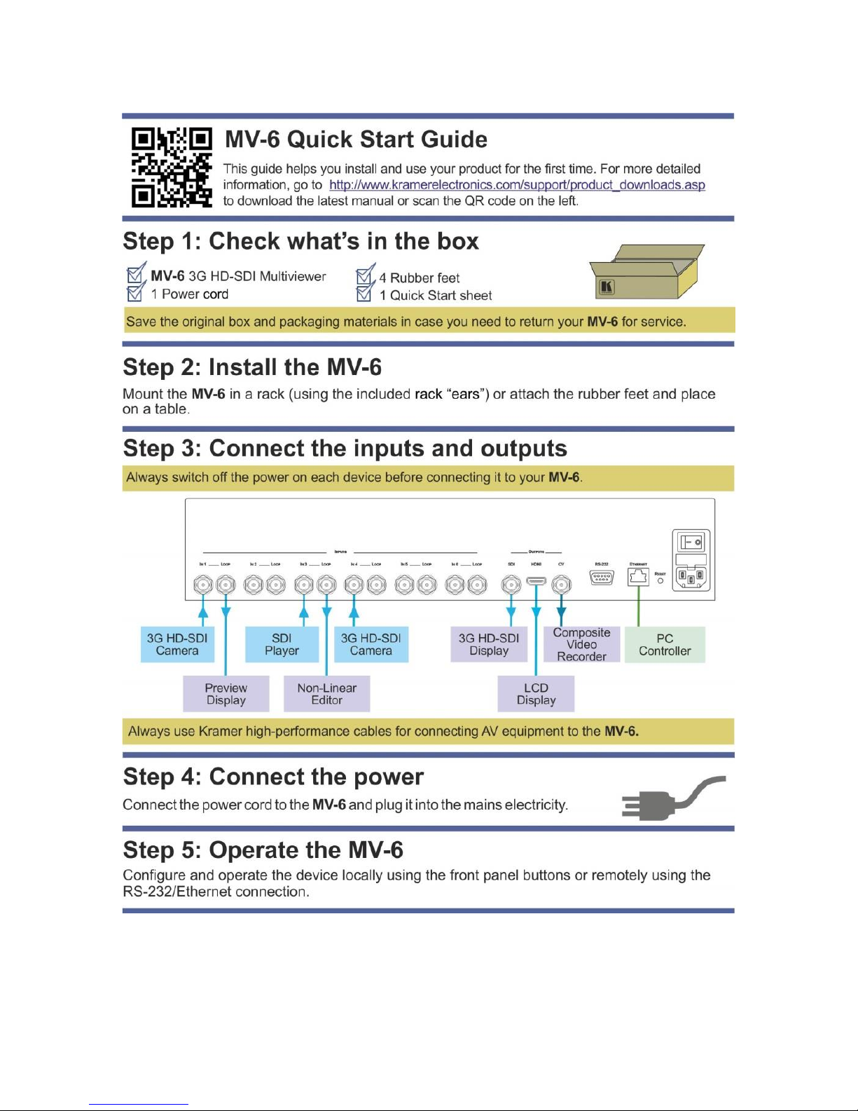
The MV-6 accepts up to six SD/HD/3G HD-SDI inputs. The device outputs a
signal (which can be any combination of the inputs) to the SDI, HDMI and
composite video connectors as shown in Figure 3.
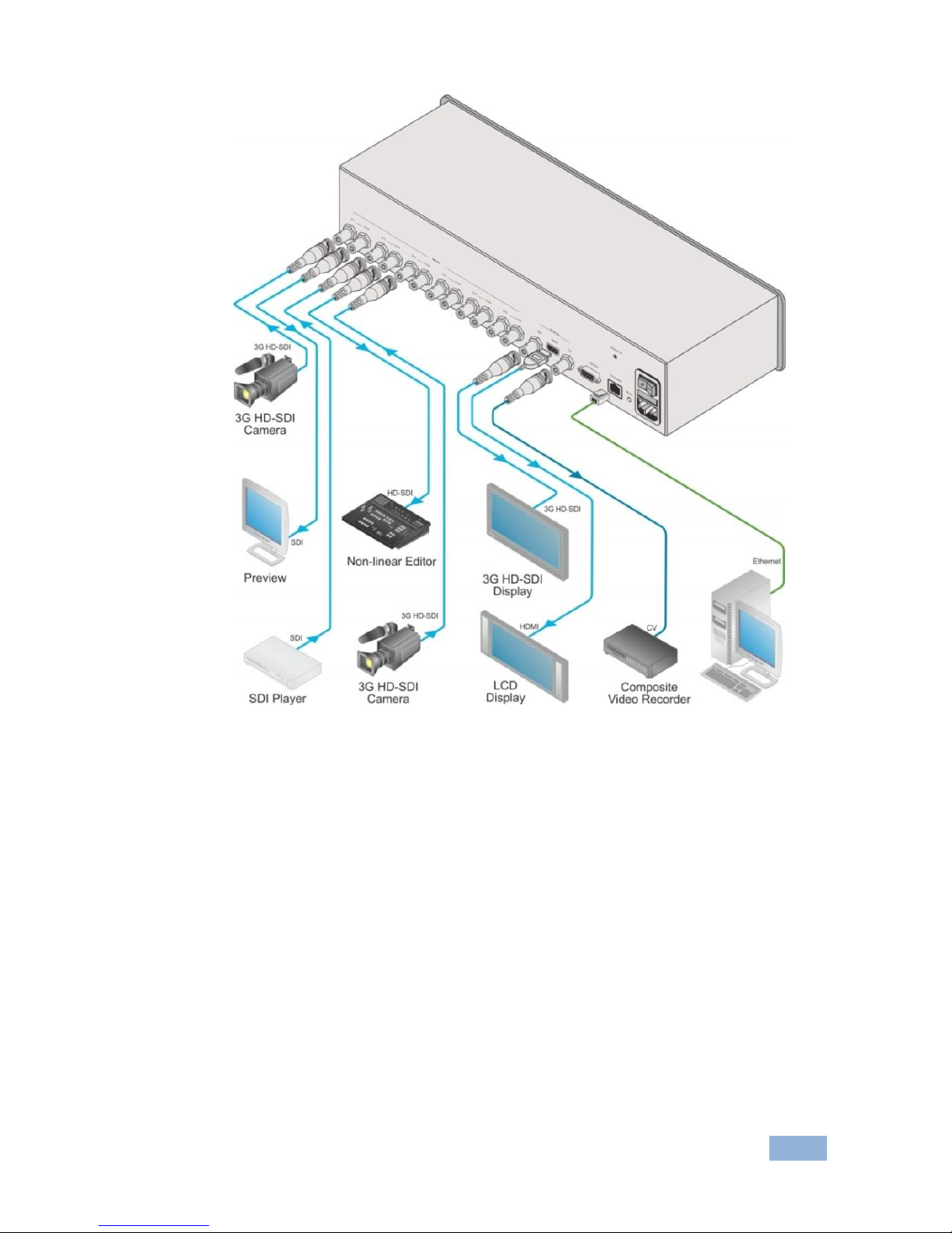
To connect the MV-6 3G HD-SDI Multiviewer as shown in Figure 3:
1. Connect up to six SDI sources (SD, HD or 3G HD-SDI) to the INPUT
BNC connectors (for example, 3G HD-SDI cameras to IN 1 and IN 3, and
an SDI player to IN 2).
2. Connect up to six SDI acceptors (SD, HD or 3G HD-SDI) to the INPUT
LOOP BNC connectors (for example, a preview SDI display to IN 1—
LOOP and a non-linear editor to IN 2—LOOP).
3. Connect up to three display acceptors to the OUTPUT connectors (for
example, a 3G HD-SDI display to the OUTPUT SDI BNC connector, an
LCD display to the HDMI connector, and a CV video recorder to the
OUTPUT CV BNC connector).
4. Optional—Connect a PC and/or serial controller to the:
Ethernet connector (see Section 5.2)
—and/or—
RS-232 port (see Section 5.1)
5. Connect the power cord (not shown in the illustration).
i
MV-6 - Connecting the MV-6
11
Figure 3: Connecting the MV-6 3G HD-SDI Multiviewer
5.1 Connecting to the RS-232 Port
You can connect to the MV-6 via an RS-232 connection using, for example, a
PC. Note that a null-modem adapter/connection is not required.
To connect to the MV-6 via RS-232:
Connect the RS-232 9-pin D-sub rear panel port on the MV-6 via a 9-wire
straight cable (only pin 2 to pin 2, pin 3 to pin 3, and pin 5 to pin 5 need to
be connected) to the RS-232 9-pin D-sub port on your PC

12
MV-6 - Connecting the MV-6
5.2 Connecting via Ethernet
You can connect to the MV-6 via Ethernet using either of the following
methods:
Directly to the PC using a crossover cable (see Section 5.2.1)
Via a network hub, switch, or router, using a straight-through cable (see
Section 5.2.2)
Note: If you want to connect via a router and your IT system is based on IPv6,
speak to your IT department for specific installation instructions.
5.2.1 Connecting the Ethernet Port Directly to a PC
You can connect the Ethernet port of the MV-6 directly to the Ethernet port on
your PC using a crossover cable with RJ-45 connectors.
This type of connection is recommended for identifying the MV-6
with the factory configured default IP address.
After connecting the MV-6 to the Ethernet port, configure your PC as follows:
1. Click Start > Control Panel > Network and Sharing Center.
2. Click Change Adapter Settings.
3. Highlight the network adapter you want to use to connect to the device
and click Change settings of this connection.
The Local Area Connection Properties window for the selected network
adapter appears as shown in Figure 4.
i

MV-6 - Connecting the MV-6
13
Figure 4: Local Area Connection Properties Window
4. Highlight either Internet Protocol Version 6 (TCP/IPv6) or Internet
Protocol Version 4 (TCP/IPv4) depending on the requirements of your
IT system.
5. Click Properties.
The Internet Protocol Properties window relevant to your IT system
appears.
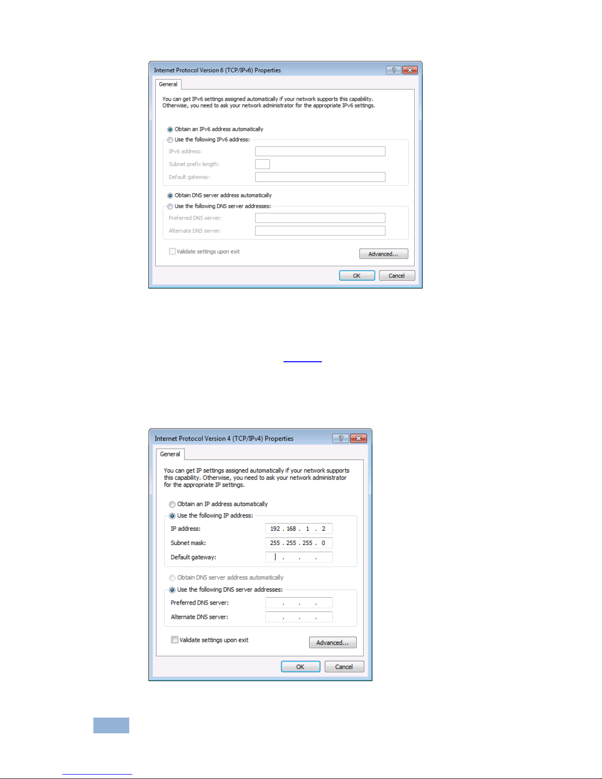
Figure 5: Internet Protocol Version 4 Properties Window
14
MV-6 - Connecting the MV-6
Figure 6: Internet Protocol Version 6 Properties Window
6. Select Use the following IP Address for static IP addressing and fill in
the details as shown in Figure 7.
For TCP/IPv4 you can use any IP address in the range 192.168.1.1 to
192.168.1.255 (excluding 192.168.1.39) that is provided by your IT
department.
Figure 7: Internet Protocol Properties Window

MV-6 - Connecting the MV-6
15
7. Click OK.
8. Click Close.
5.2.2 Connecting the Ethernet Port via a Network Hub or Switch
You can connect the Ethernet port of the MV-6 to the Ethernet port on a
network hub or using a straight-through cable with RJ-45 connectors.
5.2.3 Control Configuration via the Ethernet Port
To control several units via Ethernet, connect the Master unit (Device 1) via the
Ethernet port to the Ethernet port of your PC. Use your PC provide initial
configuration of the settings (see Section 5.2).

16
MV-6 - Operating the MV-6 Locally
6 Operating the MV-6 Locally
The MV-6 sports an LCD video preview screen on which the live video output is
shown. Changes made to the device configuration are reflected immediately on
the screen allowing you to monitor the output in real-time.
The MV-6 is operated locally using the front panel buttons.
6.1 Using the Display
When the MV-6 is powered on, the following is displayed briefly:
MV6 Multiviewer
KRAMER
The device then performs a self-test. If the test is successful the Window/Input
list is displayed, an example of which is shown below.
WIN A B C D E F
INP 2 4 5 6 1 3
During operation, if there is no button activity for approximately 60 seconds the
display reverts to the Window/Input list.
6.2 Adjusting the Size of a Window
The horizontal and vertical size of each window can be modified.
To adjust the size of a window:
1. Select the required window by pressing one of the Window buttons.
The relevant button lights.
2. Press either the H Size or V Size button to adjust the width or height of
the selected window.

MV-6 - Operating the MV-6 Locally
17
3. Use the left (◄) and right (►) buttons to adjust the window width, and
use the up (▲) and down button (▼) to adjust the window height.
The size changes in real-time.
4. Press Menu twice to exit the window size setting.
6.3 Adjusting the Position of a Window
The horizontal and vertical position of each window can be modified.
To adjust the position of a window:
1. Select the required window by pressing one of the Window buttons.
The relevant button lights.
2. Press either the H Position or V Position button to move the window.
3. Use the left (◄) and right (►) buttons to move the window horizontally,
and use the up (▲) and down button (▼) to move the window vertically.
The position changes in real-time.
4. Press Menu twice to exit the window position setting.
6.4 Defining and Saving a Custom Window Layout
In addition to the four predefined window layouts, the MV-6 can store two
custom window layouts. Once you have defined a custom window layout you
can save it for future recall.
To define and save a custom, user-defined window layout:
1. Using the Size and Position buttons, adjust all windows to the required
configuration.
2. Press and hold either the U1 or U2 Layout button until the button flashes
once.
The window layout is stored in the respective memory.

18
MV-6 - Operating the MV-6 Locally
6.5 Recalling a Window Layout
You can select any of the four predefined or two custom window layouts using
the window layout buttons.
To select a window layout:
Press one of the six screen layout buttons.
The button flashes quickly three times and the window layout is recalled
from the memory
6.6 Freezing/Releasing a Video Output
To freeze/release a video output:
1. Select the required window to freeze.
2. Press the Freeze button (see FREEZE Button).
The button lights and the output video freezes.
3. Press the Freeze button.
The button no longer lights and the video is no longer frozen.
6.7 Locking the Front Panel
Lock the front panel buttons to prevent unwanted key presses from changing
the current configuration.
To lock the front panel:
Press and hold the Panel Lock button (see PANEL LOCK Button). The
button lights and the front panel buttons are locked. Pressing any button
causes the Locked message to display and the Lock button to flash
To unlock the front panel:
Press and hold the Panel Lock button (see PANEL LOCK Button). The
button no longer lights and the front panel buttons are unlocked

MV-6 - Operating the MV-6 Locally
19
6.8 Resetting the Device to Factory Defaults
To reset the device to the factory defaults:
1. Turn the device off.
2. Press and hold the Reset button on the rear panel of the device.
3. While holding the button depressed, turn the device on.
4. Hold the button depressed for 10 seconds and release the button.
The configuration is reset to the factory default.
6.9 Using the Menu
The menu is displayed on the character display when the Enter button is
pressed. After no button activity for about a minute, the window input list is
displayed but the menu remains open in the background at the same position it
was last left in.
Navigation through the menu is performed as follows:
Enter—display the menu or select a parameter/value
Up (▲)—scroll up through the parameter/value list
Down (▼)—scroll down through the parameter/value list
Left (◄)—move left in the current field
Right (►)—move right through the current field
Menu—Move up one level in the menu hierarchy
The main menu comprises six sections:
Windows (see Section 6.9.1)
Output (see Section 6.9.2)
Status (see Section 6.9.3)
Comm Settings (see Section 6.9.4)
User Presets (see Section 6.9.5)
System (see Section 6.9.6)
 Loading...