

Page 1
KIT-Z100 Quick Start
P/N:
2900- 301420QS
Rev:
1
Scan for full manual
KIT-Z100 Quick Start Guide
This guide helps you install and use your KIT-Z100 for the first time.
Go to www.kramerav.com/downloads/KIT-Z100 to download the latest user manual and check if firmware
upgrades are available.
Step 1: Check what’s in the package
ECU-Z100
1 19V DC power adapter and cord
1 Quick start guide
KT-107Z/KT-107ZRB (with restricted BW, up to 5.35GHz)
1 5.2V power adapter and cord
Tabletop mount
On-wall mount unit
1 C-USB/Micro B cable
Installation screws
Panel Mount plate
1 right-angle OTG USB cable
Step 2: Get to know your KIT-Z100
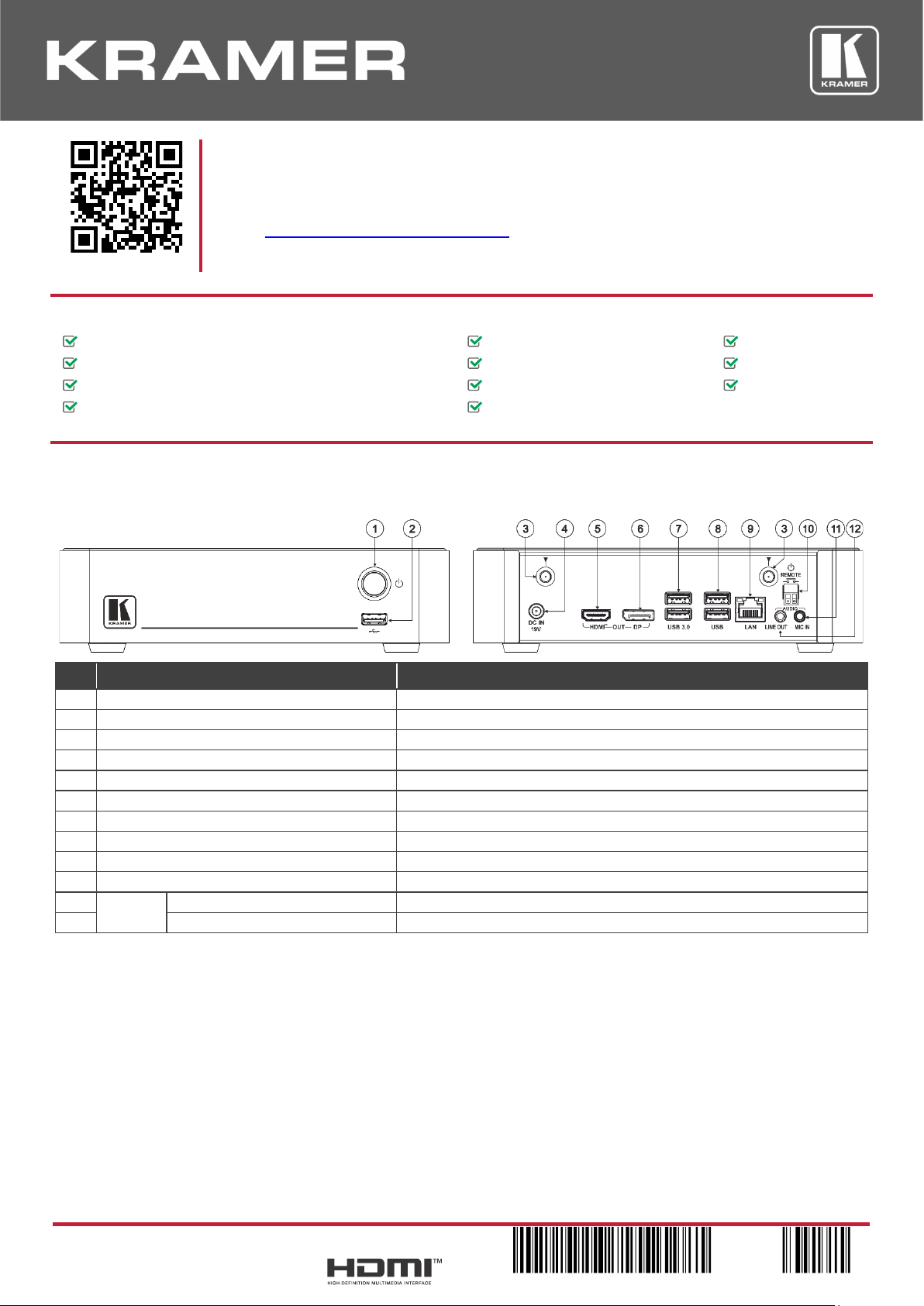
ECU-Z100
#
Feature
Function
1
Power Button
For turning the unit on and off.
2
USB 2.0 Connector
For upgrading firmware or connecting a USB device.
3
Wi-Fi Antenna Port (2)
Connect the Wi-Fi antennas for collaborating via the built-in Wi-Fi.
4
DC IN 19V Connector
Connect to the 19V DC power adapter.
5
HDMI OUT Connector
Connect to an HDMI display.
6
DP OUT Connector
Connect to a DisplayPort display.
7
USB 3.0 Connectors
Connect to up to 2 USB devices.
8
USB 2.0 Connectors
Connect to up to 2 USB devices.
9
LAN RJ-45 Connector
Connect a Local Area Network (LAN) cable.
10
REMOTE 2-pin Terminal Block Connector
Connect to a toggle switch to remotely turn the device on and off.
11
AUDIO
MIC IN 3.5mm Mini Jack
Connect to a microphone.
12
LINE OUT 3.5mm Mini Jack
Connect to an unbalanced stereo audio acceptor.
Page 2
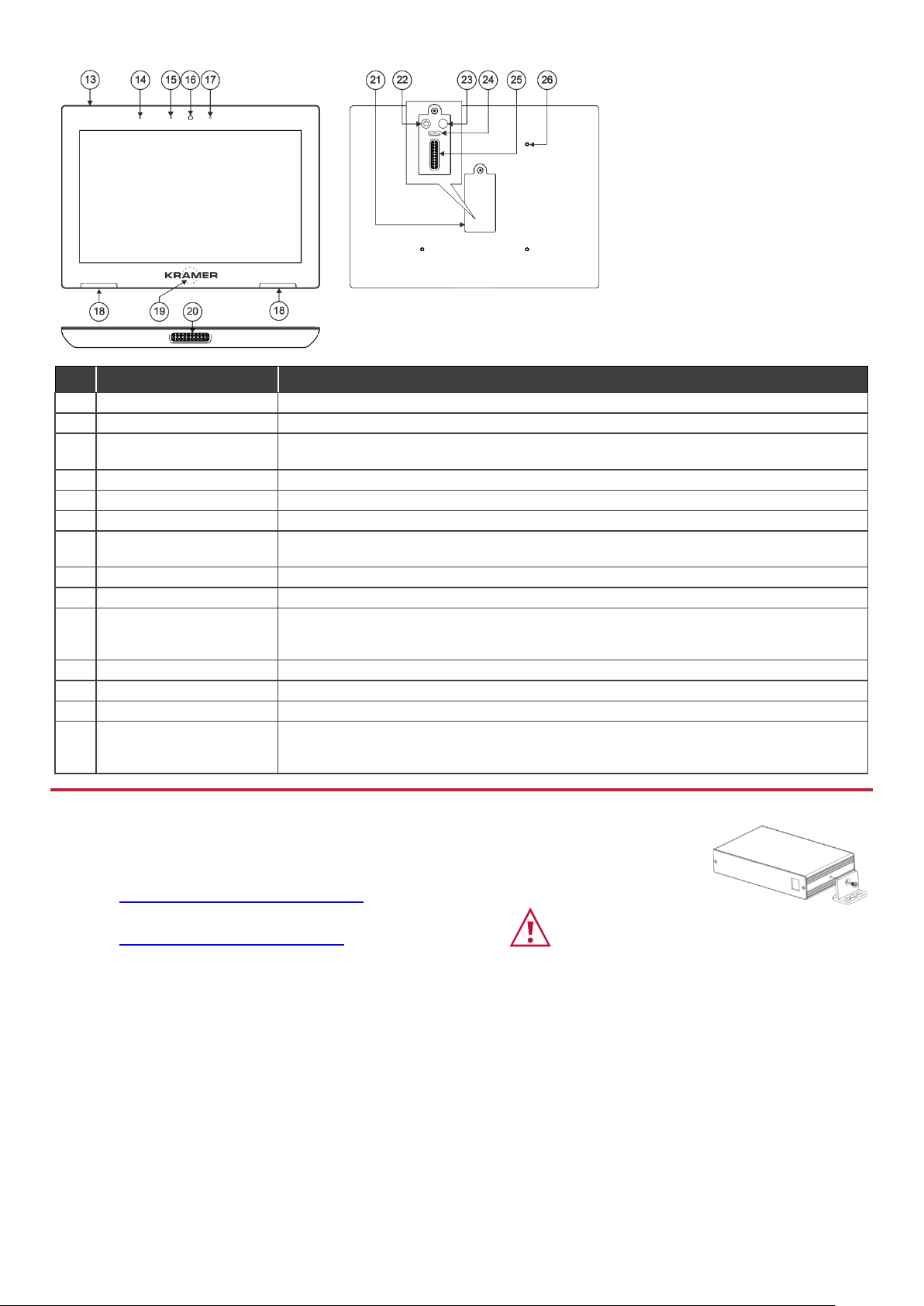
KT-107Z/KT-107ZRB
Both Table-top mount and wall mount
include the following connectors:
• A power connector, when not
using the PoE Ethernet port.
• PoE RJ-45 Ethernet Port to
connect to an Ethernet cable.
• A USB connector:
▪ For the table-top mount, a
Micro-USB port, for
connecting an external USB
device (for example, a
headset or memory disk).
▪ For the wall mount, a Type A
USB port is available using
the right-angle OTG USB
cable (included).
#
Feature
Function
13
Hidden Reset Button
Located on top-side. Insert a pin and hold for a few seconds to reset KT-107Z/KT-107ZRB.
14
Light Sensor
Automatically adjusts the screen brightness according to the room lighting conditions.
15
Activity RGB LED
Lights green when powered, flashes green when charging the battery, lights red when camera
on.
16
Camera
For remote room viewing or video conferencing.
17
Microphone
For audio communication, recording or conferencing.
18
Speakers
To output the sound.
19
Control Button
Press and hold (for 2 seconds) to power down the unit, reboot it or return to the Home-page,
via pop-up menu. This button is password protected (default: Kramer).
20
Tabletop Mount Connector
For connecting to the tabletop mount.
21
Cover
Covers the wall mount connections and power button.
22
Power Button
Press to power on the KT-107Z/KT-107ZRB. When powered, press briefly to power down the
device, reboot it or return to the Home-page, via pop-up menu. Press and hold to power down
the device immediately. This button is also used for firmware upgrade.
23
Volume-up Button
Use to increase KT-107Z/KT-107ZRB speaker volume. Use also for firmware upgrade.
24
Micro USB Port
For connecting to an adjacent on-wall USB device and for firmware upgrade.
25
Flat Cable Connector
For connecting to the on-wall mount unit.
26
Connecting Holes
For connecting to the tabletop mount or the panel mount plate.
To prevent potential damage to the KT-107Z/KT-107ZRB, use only Kramer supplied screws
and mounts.
Step 3: Mount ECU-Z100
Install ECU-Z100 using one of the following methods:
• Attach the rubber feet and place the unit on a flat surface.
• Fasten a bracket (included) on each side of the unit and attach it to a flat surface
(see www.kramerav.com/downloads/KIT-Z100).
• Mount the unit in a rack using the recommended rack adapter
(see www.kramerav.com/product/KIT-Z100).
• Ensure that the environment (e.g., maximum ambient temperature &
air flow) is compatible for the device.
• Avoid uneven mechanical loading.
• Appropriate consideration of equipment nameplate ratings should be
used for avoiding overloading of the circuits.
• Reliable earthing of rack-mounted equipment should be maintained.
Page 3

Step 4: Mount KT-107Z/KT-107ZRB
Mounting on a table using one of the following options:
Portable Mount: place the tabletop mount on the table. Connected cables remain visible and the table remains intact.
Secure Mount: secure the tabletop mount to the table as follows:
1. Measure the exact location on the surface of the table where you want to install the KT-107Z/KT-107ZRB.
2. Drill a hole in the table and optionally cut the cable pass-through opening according to the cut-out dimensions defined
in the user manual.
3. Secure the tabletop mount to the table using the M5x60 secure screw.
4. Connect the Ethernet port to a PoE-enabled source. Optionally, you can connect the power adapter too (as backup).
5. Replace the appropriate cover and place the KT-107Z/KT-107ZRB over the tabletop mount (the is magnetically held
in place), by first inserting the lower part of the then carefully laying the KT-107Z/KT-107ZRB in place.
6. Wait for the Home-page to load and then secure the KT-107Z/KT-107ZRB to the tabletop mount from the rear side
(using 2 M2x4 screws, supplied with the unit).
7. Optionally, lock the tabletop mount with a Kensington locker (not supplied).
Mounting on the wall:
Before mounting KIT-Z100 on a wall, install an in-wall junction box (recommended boxes are listed in the user manual)
1. Attach the on-wall mount unit to the installed junction box (top side up see indication arrows on unit).
Connect Ethernet and/or power cables and optionally, insert the right-angle USB cable (supplied) for connecting to an
adjacent external USB device.
2. Screw the 4 wall-mounting screws (supplied) through the screw openings.
The various screw openings fit various types of wall junction boxes.
3. On the rear side of the KT-107Z/KT-107ZRB, remove the screw
cover and the cover (by slightly pressing downwards and then
pulling out) and set aside.
4. Attach the panel mount plate to the rear side of the
KT-107Z/KT-107ZRB (using 4 M2x4 screws, supplied).
5. Connect the flat cable from the on-wall mount (attached to the
in-wall junction box) to the connector on the rear of
KT-107Z/KT-107ZRB.
6. Hang the KT-107Z/KT-107ZRB on the wall by sliding the tabs on
the attached panel mount plate over the grooves on the on-wall
mount unit.
Page 4
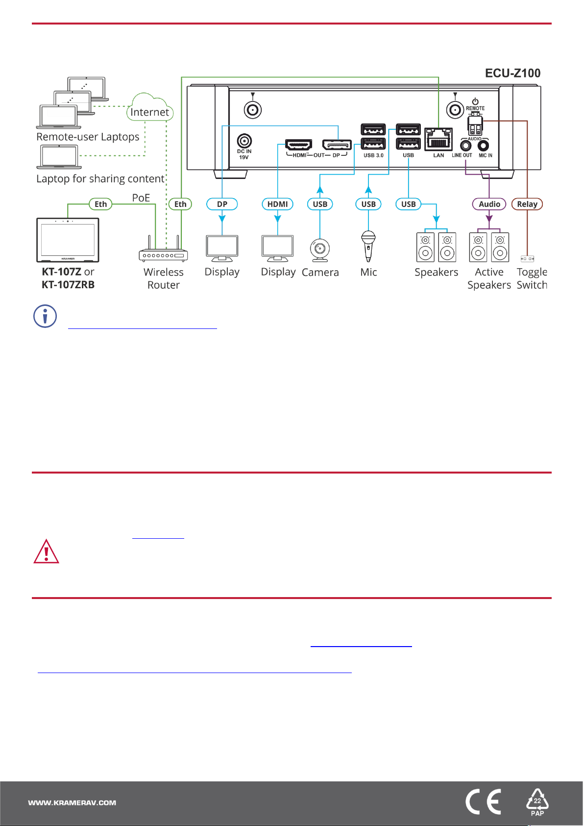
Step 5: Connect inputs and outputs
Always switch OFF the power on each device before connecting it to your KIT-Z100.
To achieve specified extension distances, use the recommended Kramer cables available at
www.kramerav.com/product/KIT-Z100. Using third-party cables may cause damage!
Microphone and speakers can be connected to ECU-Z100 in the following ways:
• Speakers can be connected via LINE OUT connector and/or USB ports.
• Microphones cab be connected via MIC IN connector (via amp) and/or USB ports.
• Speakerphones (combining a speaker and a microphone) can be connected via USB ports.
KT-107Z/KT-107ZRB can be powered in any of the following ways:
• Using the power adapter when connected by LAN (without PoE support).
• Using the power adapter when connected to LAN by Wi-Fi
• By PoE when connecting to Ethernet by PoE-supporting LAN.
Step 6: Connect power
Connect the power cord to ECU-Z100 and plug it into the mains electricity.
If required, connect the power adapter on the KT-107Z/KT-107ZRB to the Power 2-pin terminal block connector on the
tabletop mount and to the mains power.
Safety Instructions (See www.kramerav.com for updated safety information)
Caution:
• There are no operator serviceable parts inside the unit.
Warning:
• Use only the power cord that is supplied with the unit.
• Disconnect the power and unplug the unit from the wall before installing.
• Do not open the unit. High voltages can cause electrical shock! Servicing by qualified personnel only.
• To ensure continuous risk protection, replace fuses only according to the rating specified on the product label which located on the bottom of the unit.
Step 7: Set and operate KIT-Z100
Before setting up the application on KT-107Z/KT-107ZRB, you need to acquire Zoom Rooms licenses.
To set and operate the application, go to the Zoom Rooms website at support.zoom.us/hc/en-us.
To use the Zoom Rooms widget on Kramer Control, go to Zoom Rooms settings at
www.manula.com/manuals/kramer/kramer-control/1/en/topic/zoom-room-module.
 Loading...