

Page 1
Protocol 3000
Kramer devices can be operated using Kramer Protocol 3000 commands sent via serial or
Ethernet ports.
Understanding Protocol 3000
Protocol 3000 commands are a sequence of ASCII letters, structured according to the
following.
• Command format:
Prefix
Command Name
Constant (Space)
Parameter(s)
Suffix
#
Command
Parameter
<CR>
• Feedback format:
Prefix
Device ID
Constant
Command Name
Parameter(s)
Suffix
~
nn @ Command
Parameter
<CR><LF>
• Command parameters – Multiple parameters must be separated by a comma (,). In
addition, multiple parameters can be grouped as a single parameter using brackets ([
and ]).
• Command chain separator character – Multiple commands can be chained in the
same string. Each command is delimited by a pipe character (|).
• Parameters attributes – Parameters may contain multiple attributes. Attributes are
indicated with pointy brackets (<…>) and must be separated by a period (.).
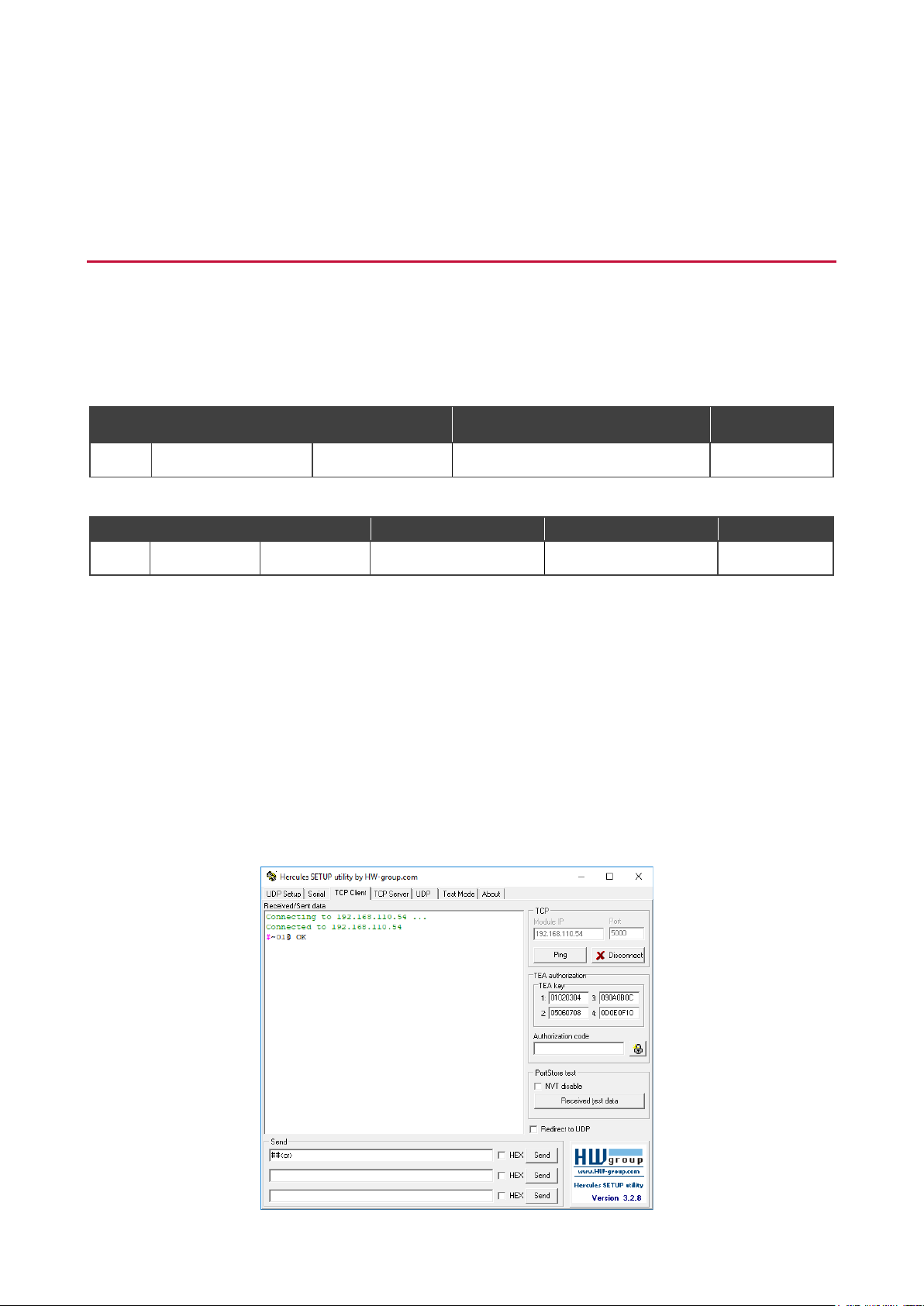
The command framing varies according to how you interface with KIT-400T. The following
figure displays how the # command is framed using terminal communication software (such
as Hercules):
Page 2
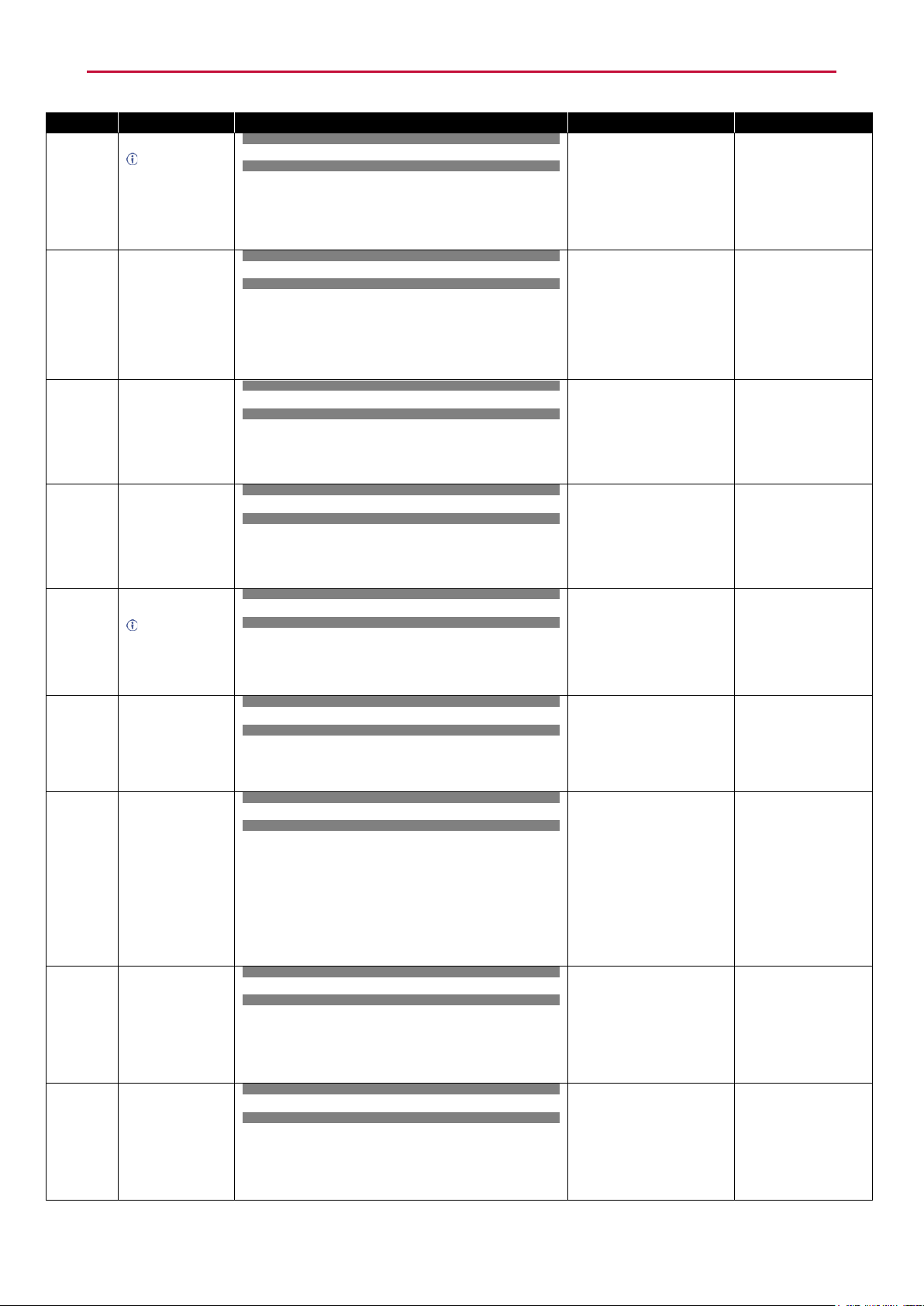
Protocol 3000 Commands
Function
Description
Syntax
Parameters/Attributes
Example
#
Protocol handshaking.
Validates the
Protocol 3000
connection and gets the
machine number.
Step-in master products
use this command to
identify the availability
of a device.
COMMAND
#<CR>
FEEDBACK
~nn@ok<CR><LF>
#<CR>
AUD-EMB?
Get audio in video
embedding status.
COMMAND
#AUD-EMB?in_index,out_index<CR>
FEEDBACK
~nn@AUD-EMBin_index,out_index,emb_mode<CR><LF>
in_index – Number that indicates
the specific input:
1 – IN 1
2 – IN 2
out_index – Number that
indicates the specific output:
1 – HDBT OUT
emb_mode – Embedding status
0 – Analog
1 – Embedded
Get IN 1 audio embedding
status:
#AUD-EMB?1,1<CR>
AUD-LVL
Set volume level.
COMMAND
#AUD-LVLio_mode,io_index,vol_level<CR>
FEEDBACK
~nn@AUD-LVLio_mode,io_index,vol_level<CR><LF>
io_mode – Input/Output
1 – Output
io_index – Number that indicates
the specific input or output port:
1 – AUDIO OUT
vol_level – Volume level -83db
to 24dB;
++ (increase current value by 1dB);
-- (decrease current value by 1dB)
Set AUDIO OUT level
to -50dB:
#AUD-LVL1,1,-50<CR>
AUD-LVL?
Get volume level.
COMMAND
#AUD-LVL?io_mode,io_index<CR>
FEEDBACK
~nn@AUD-LVLio_mode,io_index,vol_level<CR><LF>
io_mode – Input/Output
1 – Output
io_index – Number that indicates
the specific input or output port:
1 – AUDIO OUT
vol_level – Volume level -83db
to 24dB;
++ (increase current value by 1dB);
-- (decrease current value by 1dB)
Get AUDIO OUT level
#AUD-LVL?1,1<CR>
AUD-LVLRANGE?
Get audio level min and
max range.
In most devices min
and max audio level is
a function of HW
implementation and the
SET command is
usually not
implemented.
COMMAND
#AUD-LVL-RANGE?io_mode,io_index<CR>
FEEDBACK
~nn@AUD-LVL-RANGEio_mode,io_index,min_vol,max_vol<CR><L
F>
io_mode – Input/Output
0 – Input
1 – Output
io_index – Number that indicates
the specific input or output port:
1-N (N= the total number of input or
output ports)
min_vol – -83dB
max_vol – 24dB audio level
Get audio level min and max
range for output 1 channel 2:
#AUD-LVL-RANGE?1,2<C
R>
AUDSIGNAL?
Get audio input signal
status.
COMMAND
#AUD-SIGNAL?in_index<CR>
FEEDBACK
~nn@AUD-SIGNALin_index,status<CR><LF>
in_index – Number that indicates
the specific input:
1 – IN 1
2 – IN 2
3 – IN 3
status – On/Off
0 – Off (no signal)
1 – On (signal present)
Get the status of input 1:
#AUD-SIGNAL?1<CR>
AV-SWMODE?
Get input auto switch
mode (per output).
COMMAND
#AV-SW-MODE?layer_type,out_index<CR>
FEEDBACK
~nn@AV-SW-MODElayer_type,out_index,connection_mode<CR><
LF>
layer_type – Number that
indicates the signal type:
1 – Video
2 – Audio
out_index – Number that
indicates the specific output:
for video layer:
1 – HDBT OUT
for audio layer
1 – Audio Out
connection_mode – Connection
mode
0 – manual
1 – priority switch
2 – last connected switch
Get the input audio switch
mode for HDBT Out:
#AV-SW-MODE?1,1<CR>
AV-SWTIMEOUT
Set auto switching
timeout.
COMMAND
#AV-SW-TIMEOUTswitching_mode,time_out<CR>
FEEDBACK
~nn@AV-SW-TIMEOUTswitching_mode,time_out<CR><LF>
switching_mode – Switching
mode
0 – Video signal lost
2 – Audio signal lost
4 – Disable 5V on video output if
no input signal detected
5 – Video cable unplugged
6 – Audio cable unplugged
time_out – Timeout in seconds
0 - 60000
Set the auto switching
timeout to 5 seconds in the
event of 5V disable when no
input signal is detected:
#AV-SW-TIMEOUT4,5<CR
>
AV-SWTIMEOUT?
Get auto switching
timeout.
COMMAND
#AV-SW-TIMEOUT?switching_mode<CR>
FEEDBACK
~nn@AV-SW-TIMEOUTswitching_mode,time_out<CR><LF>
switching_mode – Switching
mode
0 – Video signal lost
2 – Audio signal lost
4 – Disable 5V on video output if
no input signal detected
5 – Video cable unplugged
6 – Audio cable unplugged
time_out – Timeout in seconds
0 - 60000
Get the Disable 5V on video
output if no input signal
detected timeout:
#AV-SW-TIMEOUT?4<CR>
Page 3
Function
Description
Syntax
Parameters/Attributes
Example
BEACONINFO?
Get beacon
information, including
IP address, UDP
control port, TCP
control port, MAC
address, model, name.
There is no Set
command. Get
command initiates a
notification.
COMMAND
#BEACON-INFO?port_id<CR>
FEEDBACK
~nn@BEACON-INFOport_id,ip_string,udp_port,tcp_port,mac_
address,model,name<CR><LF>
port_id – ID of the Ethernet port
ip_string – Dot-separated
representation of the IP address
udp_port – UDP control port
tcp_port – TCP control port
mac_address – Dash-separated
mac address
model – Device model
name – Device name
Get beacon information:
#BEACON-INFO?<CR>
BUILDDATE?
Get device build date.
COMMAND
#BUILD-DATE?<CR>
FEEDBACK
~nn@BUILD-DATEdate,time<CR><LF>
date – Format: YYYY/MM/DD
where
YYYY = Year
MM = Month
DD = Day
time – Format: hh:mm:ss where
hh = hours
mm = minutes
ss = seconds
Get the device build date:
#BUILD-DATE?<CR>
CPEDID
Copy EDID data from
the output to the input
EEPROM.
Destination bitmap
size depends on device
properties (for 64 inputs
it is a 64-bit word).
Example: bitmap
0x0013 means inputs
1,2 and 5 are loaded
with the new EDID.
In certain products
Safe_mode is an
optional parameter.
See the HELP
command for its
availability.
COMMAND
#CPEDIDedid_io,src_id,edid_io,dest_bitmap<CR>
or
#CPEDIDedid_io,src_id,edid_io,dest_bitmap,safe_mode<CR>
FEEDBACK
~nn@CPEDIDedid_io,src_id,edid_io,dest_bitmap<CR><LF>
~nn@CPEDIDedid_io,src_id,edid_io,dest_bitmap,safe_mode<
CR><LF>
edid_io – EDID source type
(usually output)
0 – Input
1 – Output
2 – Default EDID
src_id – Number of chosen
source stage
for input source:
1 – IN 1
2 – IN 2
3 – IN 3
for output source:
1 – HDBT OUT
for default source:
0 – Default EDID source
edid_io – EDID destination type
(usually input)
0 – Input
1 – Output
2 – Default EDID
dest_bitmap – Bitmap
representing destination IDs.
Format: XXXX…X, where X is hex
digit. The binary form of every hex
digit represents corresponding
destinations.
0 – indicates that EDID data is not
copied to this destination.
1 – indicates that EDID data is
copied to this destination.
safe_mode – Safe mode
0 – device accepts the EDID as is
without trying to adjust
1 – device tries to adjust the EDID
(default value if no parameter
is sent)
Copy the EDID data from the
HDBT OUT (EDID source) to
the Input:
#CPEDID1,1,0,0x1<CR>
Copy the EDID data from the
default EDID source to the
Input:
#CPEDID2,0,0,0x1<CR>
DISPLAY?
Get output HPD status.
COMMAND
#DISPLAY?out_index<CR>
FEEDBACK
~nn@DISPLAYout_index,status<CR><LF>
out_index – Number that
indicates the specific output:
1 – HDBT OUT
status – HPD status according to
signal validation
0 – Signal or sink is not valid
1 – Signal or sink is valid
2 – Sink and EDID is valid
Get the HDBT OUT HPD
status of Output 1:
#DISPLAY?1<CR>
DPSWSTATUS?
Get the DIP-switch
state.
COMMAND
#DPSW-STATUS?dip_id<CR>
FEEDBACK
~nn@DPSW-STATUSdip_id,status<CR><LF>
dip_id – 1 to 4 (number of DIP
switches)
1 – Video switch 1
2 – Video switch 2
3 – Audio switch 3
4 – Audio switch 4
status – Up/down
0 – Up
1 – Down
get the DIP-switch 2 status:
#DPSW-STATUS?2<CR>
ETH-PORT
Set Ethernet port
protocol.
If the port number
you enter is already in
use, an error is
returned.
The port number must
be within the following
range: 0-(2^16-1).
COMMAND
#ETH-PORTport_type,port_id<CR>
FEEDBACK
~nn@ETH-PORTport_type,port_id<CR><LF>
port_type – TCP/UDP
port_id – TCP/UDP port number
(0 – 65535)
Set the Ethernet port
protocol for TCP to port
12457:
#ETH-PORT0,12457<CR>
ETH-PORT?
Get Ethernet port
protocol.
COMMAND
#ETH-PORT?port_type<CR>
FEEDBACK
~nn@ETH-PORTport_type,port_id<CR><LF>
port_type – TCP/UDP
0 – TCP
1 – UDP
port_id – TCP / UDP port number
(0 – 65535)
Get the Ethernet port
protocol for UDP:
#ETH-PORT?1<CR>
Page 4
Function
Description
Syntax
Parameters/Attributes
Example
FACTORY
Reset device to factory
default configuration.
This command
deletes all user data
from the device. The
deletion can take some
time.
Your device may
require powering off
and powering on for the
changes to take effect.
COMMAND
#FACTORY<CR>
FEEDBACK
~nn@FACTORYok<CR><LF>
Reset the device to factory
default configuration:
#FACTORY<CR>
FPGA-VER?
Get current FPGA
version.
COMMAND
#FPGA-VER?fpga_id<CR>
FEEDBACK
~nn@FPGA-VERfpga_id,expected_ver,ver<CR><LF>
fpga_id – FPGA id
expected_ver – Expected FPGA
version for current firmware
ver – Actual FPGA version
Get current FPGA version:
#FPGA-VER?1<CR>
HDCP-MOD
Set HDCP mode.
Set HDCP working
mode on the device
input:
HDCP supported HDCP_ON [default].
HDCP not supported HDCP OFF.
HDCP support changes
following detected sink
- MIRROR OUTPUT.
When you define 3 as
the mode, the HDCP
status is defined
according to the
connected output in the
following priority: OUT
1, OUT 2. If the
connected display on
OUT 2 supports HDCP,
but OUT 1 does not,
then HDCP is defined
as not supported. If
OUT 1 is not
connected, then HDCP
is defined by OUT 2.
COMMAND
#HDCP-MODin_index,mode<CR>
FEEDBACK
~nn@HDCP-MODin_index,mode<CR><LF>
in_index – Number that indicates
the specific input:
1 – IN 1
2 – IN 2
3 – IN 3
mode – HDCP mode:
0 – HDCP Off
3 – HDCP defined according to
the connected output (MAC
mode)
Set the input HDCP-MODE
of IN 1 to Off:
#HDCP-MOD1,0<CR>
HDCP-MOD?
Get HDCP mode.
Set HDCP working
mode on the device
input:
HDCP supported HDCP_ON [default].
HDCP not supported HDCP OFF.
HDCP support changes
following detected sink
- MIRROR OUTPUT.
COMMAND
#HDCP-MOD?in_index<CR>
FEEDBACK
~nn@HDCP-MODin_index,mode<CR><LF>
in_index – Number that indicates
the specific input:
1 – IN 1
2 – IN 2
3 – IN 3
mode – HDCP mode:
0 – HDCP Off
3 – HDCP defined according to
the connected output (MAC
mode)
Get the input HDCP-MODE
of IN 1 HDMI:
#HDCP-MOD?1<CR>
HDCPSTAT?
Get HDCP signal
status.
io_mode =1 – get
the HDCP signal status
of the sink device
connected to the
specified output.
io_mode =0 – get the
HDCP signal status of
the source device
connected to the
specified input.
COMMAND
#HDCP-STAT?io_mode,in_index<CR>
FEEDBACK
~nn@HDCP-STATio_mode,in_index,status<CR><LF>
io_mode – Input/Output
0 – Input
1 – Output
io_index – Number that indicates
the specific number of inputs or
outputs (based on io_mode):
for Input:
1 – IN 1
2 – IN 2
3 – IN 3
for output:
1 – HDBT OUT
status – Signal encryption status -
valid values On/Off
0 – HDCP Off
1 – HDCP On
Get the output HDCPSTATUS of IN 1:
#HDCP-STAT?0,1<CR>
HELP
Get command list or
help for specific
command.
COMMAND
#HELP<CR>
#HELPcmd_name<CR>
FEEDBACK
1. Multi-line:
~nn@Devicecmd_name,cmd_name…<CR><LF>
To get help for command use: HELP (COMMAND_NAME)<CR><LF>
~nn@HELPcmd_name:<CR><LF>
description<CR><LF>
USAGE:usage<CR><LF>
cmd_name – Name of a specific
command
Get the command list:
#HELP<CR>
To get help for
AV-SW-TIMEOUT:
HELPav-sw-timeout<C
R>
LOCK-EDID
Lock last read EDID.
COMMAND
#LOCK-EDIDin_index,lock_mode<CR>
FEEDBACK
~nn@LOCK-EDIDin_index,lock_mode<CR><LF>
in_index – Number that indicates
the specific input:
1 – IN 1
2 – IN 2
3 – IN 3
lock_mode – On/Off
0 – Off unlocks EDID
1 – On locks EDID
Lock the last read EDID from
the HDMI In 2 input:
#LOCK-EDID2,1<CR>
Page 5
Function
Description
Syntax
Parameters/Attributes
Example
LOCKEDID?
Get EDID lock state.
COMMAND
#LOCK-EDID?in_index,<CR>
FEEDBACK
~nn@LOCK-EDIDin_index,lock_mode<CR><LF>
in_index – Number that indicates
the specific input:
1 – IN 1
2 – IN 2
3 – IN 3
lock_mode – On/Off
0 – Off unlocks EDID
1 – On locks EDID
Get EDID lock state for Input
2:
#LOCK-EDID?2<CR>
LOGIN
Set protocol
permission.
The permission
system works only if
security is enabled with
the “SECUR”
command.
LOGIN allows the user
to run commands with
an End User or
Administrator
permission level.
When the permission
system is enabled,
LOGIN enables running
commands with the
User or Administrator
permission level
When set, login must
be performed upon
each connection
It is not mandatory to
enable the permission
system in order to use
the device
In each device, some
connections allow
logging in to different
levels. Some do not
work with security at all.
Connection may logout
after timeout.
COMMAND
#LOGINlogin_level,password<CR>
FEEDBACK
~nn@LOGINlogin_level,passwordok<CR><LF>
or
~nn@LOGINerr004<CR><LF>
(if bad password entered)
login_level – Level of
permissions required (User or
Admin)
password – Predefined password
(by PASS command). Default
password is an empty string
Set the protocol permission
level to Admin (when the
password defined in the
PASS command is 33333):
#LOGINadmin,33333<CR
>
LOGIN?
Get current protocol
permission level.
The permission
system works only if
security is enabled with
the “SECUR”
command.
For devices that
support security,
LOGIN allows the user
to run commands with
an End User or
Administrator
permission level.
In each device, some
connections allow
logging in to different
levels. Some do not
work with security at all.
Connection may logout
after timeout.
COMMAND
#LOGIN?<CR>
FEEDBACK
~nn@LOGINlogin_level<CR><LF>
login_level – Level of
permissions required (User or
Admin)
Get current protocol
permission level:
#LOGIN?<CR>
LOGOUT
Cancel current
permission level.
Logs out from End
User or Administrator
permission levels to Not
Secure.
COMMAND
#LOGOUT<CR>
FEEDBACK
~nn@LOGOUTok<CR><LF>
#LOGOUT<CR>
MODEL?
Get device model.
This command
identifies equipment
connected to KIT-400T
and notifies of identity
changes to the
connected equipment.
The Matrix saves this
data in memory to
answer REMOTE-INFO
requests.
COMMAND
#MODEL?<CR>
FEEDBACK
~nn@MODELmodel_name<CR><LF>
model_name – String of up to 19
printable ASCII chars
Get the device model:
#MODEL?<CR>
MUTE
Set audio mute.
COMMAND
#MUTEout_index,mute_mode<CR>
FEEDBACK
~nn@MUTEout_index,mute_mode<CR><LF>
out_index – Number that
indicates the specific output:
1 – AUDIO OUT
mute_mode – On/Off
0 – Off
1 – On
Set Output 1 to mute:
#MUTE1,1<CR>
Page 6
Function
Description
Syntax
Parameters/Attributes
Example
MUTE?
Get audio mute.
COMMAND
#MUTE?out_index<CR>
FEEDBACK
~nn@MUTEout_index,mute_mode<CR><LF>
out_index – Number that
indicates the specific output:
1 – AUDIO OUT
mute_mode – On/Off
0 – Off
1 – On
Get mute status of output 1
#MUTE1?<CR>
NAME
Set machine (DNS)
name.
The machine name
is not the same as the
model name. The
machine name is used
to identify a specific
machine or a network in
use (with DNS feature
on).
COMMAND
#NAMEmachine_name<CR>
FEEDBACK
~nn@NAMEmachine_name<CR><LF>
machine_name – String of up to 15
alpha-numeric chars (can include
hyphen, not at the beginning or end)
Set the DNS name of the
device to room-442:
#NAMEroom-442<CR>
NAME?
Get machine (DNS)
name.
The machine name
is not the same as the
model name. The
machine name is used
to identify a specific
machine or a network in
use (with DNS feature
on).
COMMAND
#NAME?<CR>
FEEDBACK
~nn@NAMEmachine_name<CR><LF>
machine_name – String of up to 15
alpha-numeric chars (can include
hyphen, not at the beginning or end)
Get the DNS name of the
device:
#NAME?<CR>
NAME-RST
Reset machine (DNS)
name to factory default.
Factory default of
machine (DNS) name is
“KRAMER_” + 4 last
digits of device serial
number.
COMMAND
#NAME-RST<CR>
FEEDBACK
~nn@NAME-RSTok<CR><LF>
Reset the machine name
(S/N last digits are 0102):
#NAMERSTkramer_0102<CR>
NETCONFIG
Set a network
configuration.
Parameters [DNS1]
and [DNS2]are
optional.
For Backward
compatibility, the id
parameter can be
omitted. In this case,
the Network ID, by
default, is 0, which is
the Ethernet control
port.
If the gateway
address is not
compliant to the subnet
mask used for the host
IP, the command will
return an error. Subnet
and gateway
compliancy specified by
RFC950.
COMMAND
#NET-CONFIGnetw_id,net_ip,net_mask,gateway,[dns1],[dns2
]<CR>
FEEDBACK
~nn@NET-CONFIGnetw_id,net_ip,net_mask,gateway<CR><LF>
netw_id – Network ID–the device
network interface (if there are more
than one). Counting is 0 based,
meaning the control port is ‘0’,
additional ports are 1,2,3….
net_ip – Network IP
net_mask – Network mask
gateway – Network gateway
Set the device network
parameters to IP address
192.168.113.10, net mask
255.255.0.0, and gateway
192.168.0.1:
#NET-CONFIG0,192.168
.113.10,255.255.0.0,1
92.168.0.1<CR>
NETCONFIG?
Get a network
configuration.
COMMAND
#NET-CONFIG?netw_id<CR>
FEEDBACK
~nn@NET-CONFIGnetw_id,net_ip,net_mask,gateway<CR><LF>
netw_id – Network ID–the device
network interface (if there are more
than one). Counting is 0 based,
meaning the control port is ‘0’,
additional ports are 1,2,3….
net_ip – Network IP
net_mask – Network mask
gateway – Network gateway
Get network configuration:
#NET-CONFIG?id<CR>
Page 7
Function
Description
Syntax
Parameters/Attributes
Example
NET-DHCP
Set DHCP mode.
Only 1 is relevant
for the mode value. To
disable DHCP, the user
must configure a static
IP address for the
device.
Connecting Ethernet to
devices with DHCP
may take more time in
some networks.
To connect with a
randomly assigned IP
by DHCP, specify the
device DNS name (if
available) using the
NAME command. You
can also get an
assigned IP by direct
connection to USB or
RS-232 protocol port, if
available.
For proper settings
consult your network
administrator.
For Backward
compatibility, the id
parameter can be
omitted. In this case,
the Network ID, by
default, is 0, which is
the Ethernet control
port.
COMMAND
#NET-DHCPnetw_id,dhcp_state<CR>
FEEDBACK
~nn@NET-DHCPnetw_id,dhcp_state<CR><LF>
netw_id – Network ID–the device
network interface (if there are more
than one). Counting is 0 based,
meaning the control port is ‘0’,
additional ports are 1,2,3….
dhcp_state –
1 – Try to use DHCP. (If
unavailable, use the IP
address set by the factory or
the net-ip command).
Enable DHCP mode for port
1, if available:
#NET-DHCP1,1<CR>
NET-DHCP?
Get DHCP mode.
For Backward
compatibility, the id
parameter can be
omitted. In this case,
the Network ID, by
default, is 0, which is
the Ethernet control
port.
COMMAND
#NET-DHCP?netw_id<CR>
FEEDBACK
~nn@NET-DHCPnetw_id,dhcp_mode<CR><LF>
netw_id – Network ID–the device
network interface (if there are more
than one). Counting is 0 based,
meaning the control port is ‘0’,
additional ports are 1,2,3….
dhcp_mode –
0 – Do not use DHCP. Use the IP
set by the factory or using the
net-ip or net-config
command.
1 – Try to use DHCP. If
unavailable, use the IP set by
the factory or using the net-
ip or net-config command.
Get DHCP mode for port 1:
#NET-DHCP?1<CR>
NET-GATE
Set gateway IP.
A network gateway
connects the device via
another network and
maybe over the
Internet. Be careful of
security issues. For
proper settings consult
your network
administrator.
COMMAND
#NET-GATEip_address<CR>
FEEDBACK
~nn@NET-GATEip_address<CR><LF>
ip_address – Format:
xxx.xxx.xxx.xxx
Set the gateway IP address
to 192.168.0.1:
#NETGATE192.168.000.001<
CR>
NET-GATE?
Get gateway IP.
A network gateway
connects the device via
another network and
maybe over the
Internet. Be aware of
security problems.
COMMAND
#NET-GATE?<CR>
FEEDBACK
~nn@NET-GATEip_address<CR><LF>
ip_address – Format:
xxx.xxx.xxx.xxx
Get the gateway IP address:
#NET-GATE?<CR>
NET-IP
Set IP address.
For proper settings
consult your network
administrator.
COMMAND
#NET-IPip_address<CR>
FEEDBACK
~nn@NET-IPip_address<CR><LF>
ip_address – Format:
xxx.xxx.xxx.xxx
Set the IP address to
192.168.1.39:
#NETIP192.168.001.039<CR
>
NET-IP?
Get IP address.
COMMAND
#NET-IP?<CR>
FEEDBACK
~nn@NET-IPip_address<CR><LF>
ip_address – Format:
xxx.xxx.xxx.xxx
Get the IP address:
#NET-IP?<CR>
NET-MAC?
Get MAC address.
For backward
compatibility, the id
parameter can be
omitted. In this case,
the Network ID, by
default, is 0, which is
the Ethernet control
port.
COMMAND
#NET-MAC?id<CR>
FEEDBACK
~nn@NET-MACid,mac_address<CR><LF>
id – Network ID–the device
network interface (if there are more
than one). Counting is 0 based,
meaning the control port is ‘0’,
additional ports are 1,2,3….
mac_address – Unique MAC
address. Format: XX-XX-XX-XXXX-XX where X is hex digit
#NET-MAC?id<CR>
NET-MASK
Set subnet mask.
For proper settings
consult your network
administrator.
COMMAND
#NET-MASKnet_mask<CR>
FEEDBACK
~nn@NET-MASKnet_mask<CR><LF>
net_mask – Format:
xxx.xxx.xxx.xxx
Set the subnet mask to
255.255.0.0:
#NETMASK255.255.000.000<
CR>
NET-MASK?
Get subnet mask.
COMMAND
#NET-MASK?<CR>
FEEDBACK
~nn@NET-MASKnet_mask<CR><LF>
net_mask – Format:
xxx.xxx.xxx.xxx
Get the subnet mask:
#NET-MASK?<CR>
Page 8

Function
Description
Syntax
Parameters/Attributes
Example
PASS
Set password for login
level.
The default
password is an empty
string.
COMMAND
#PASSlogin_level,password<CR>
FEEDBACK
~nn@PASSlogin_level,password<CR><LF>
login_level – Level of login to
set (End User or Administrator).
password – Password for the
login_level. Up to 15 printable ASCII
chars
Set the password for the
Admin protocol permission
level to 33333:
#PASSadmin,33333<CR>
PASS?
Get password for login
level.
The default
password is an empty
string.
COMMAND
#PASS?login_level<CR>
FEEDBACK
~nn@PASSlogin_level,password<CR><LF>
login_level – Level of login to
set (End User or Administrator).
password – Password for the
login_level. Up to 15 printable ASCII
chars
Get the password for the
Admin protocol permission
level:
#PASS?admin<CR>
PRIORITY
Set input priority.
COMMAND
#PRIORITYlayer_type,priority_1,priority_2…priority_3<CR
>
FEEDBACK
~nn@PRIORITYlayer_type,priority_1,priority_2…priority_3
<CR><LF>
layer_type – Layer Enumeration
1 – Video
2 – Audio
priority – Priority of inputs (1-n)
for video layer (1 is the highest
priority):
priority 1 –for IN 1 (1,2, or 3)
priority 2 – for IN 2 (1, 2 or 3)
priority 3 – for IN 3 (1, 2 or 3)
for audio layer (1 is the highest
priority):
priority 1 –for embedded audio
(1or 2)
priority 2 – for AUDIO IN (1 or
2)
Set the video input priority of
PC In as the highest priority:
#PRIORITY1,2,3,1<CR>
PRIORITY?
Get input priority.
COMMAND
#PRIORITY?layer_type<CR>
FEEDBACK
~nn@PRIORITYlayer_type,priority_1,priority_2…priority_n
<CR><LF>
layer_type – Layer Enumeration
1 – Video
2 – Audio
priority – Priority of inputs (1-n)
for video layer (1 is the highest
priority):
priority 1 –for IN 1 (1,2, or 3)
priority 2 – for IN 2 (1, 2 or 3)
priority 3 – for IN 3 (1, 2 or 3)
for audio layer (1 is the highest
priority):
priority 1 –for embedded audio
(1or 2)
priority 2 – for AUDIO IN (1 or
2)
Get video input priority:
#PRIORITY?1<CR>
PROT-VER?
Get device protocol
version.
COMMAND
#PROT-VER?<CR>
FEEDBACK
~nn@PROT-VER3000:version<CR><LF>
version – XX.XX where X is a
decimal digit
Get the device protocol
version:
#PROT-VER?<CR>
RESET
Reset device.
To avoid locking the
port due to a USB bug
in Windows, disconnect
USB connections
immediately after
running this command.
If the port was locked,
disconnect and
reconnect the cable to
reopen the port.
COMMAND
#RESET<CR>
FEEDBACK
~nn@RESETok<CR><LF>
Reset the device:
#RESET<CR>
ROUTE
Set layer routing.
This command
replaces all other
routing commands.
COMMAND
#ROUTElayer_type,out_index,in_index<CR>
FEEDBACK
~nn@ROUTElayer_type,out_index<CR><LF>
layer_type Layer Enumeration
1 – Video
3 – Data
out_index
for video layer:
1 – HDBT OUT
for video layer:
1 – HDBT OUT
2 – KIT-400T data port
3 – KIT-400T internal control port
in_index – Source id
for video layer:
1 – IN 1
2 – IN 2
3 – IN 3
for video layer:
1 – HDBT OUT
2 – KIT-400T data port
3 – KIT-400T internal control port
Route video IN 2 to video
HDBT OUT:
#ROUTE1,1,2<CR>
ROUTE?
Get layer routing.
This command
replaces all other
routing commands.
COMMAND
#ROUTE?layer_type,out_index<CR>
FEEDBACK
~nn@ROUTElayer_type,out_index,in_index<CR><LF>
layer_type Layer Enumeration
1 – Video
3 – Data
out_index
for video layer:
1 – HDBT OUT
for video layer:
1 – HDBT OUT
2 – KIT-400T data port
3 – KIT-400T internal control port
in_index – Source id
for video layer:
1 – IN 1
2 – IN 2
3 – IN 3
for video layer:
1 – HDBT OUT
2 – KIT-400T data port
3 – KIT-400T internal control port
Get the layer routing:
#ROUTE?1,1<CR>
Page 9
Function
Description
Syntax
Parameters/Attributes
Example
SECUR
Start/stop security.
The permission
system works only if
security is enabled with
the “SECUR”
command.
COMMAND
#SECURsecurity_state<CR>
FEEDBACK
~nn@SECURsecurity_state<CR><LF>
security_state – Security state
0 – OFF (disables security)
1 – ON (enables security)
Enable the permission
system:
#SECUR0<CR>
SECUR?
Get current security
state.
The permission
system works only if
security is enabled with
the “SECUR”
command.
COMMAND
#SECUR?<CR>
FEEDBACK
~nn@SECURsecurity_state<CR><LF>
security_state – Security state
0 – OFF (disables security)
1 – ON (enables security)
Get current security state:
#SECUR?<CR>
SIGNAL?
Get input signal status.
COMMAND
#SIGNAL?in_index<CR>
FEEDBACK
~nn@SIGNALin_index,status<CR><LF>
in_index – Number that indicates
the specific input:
1 – IN 1
2 – IN 2
3 – IN 3
status – Signal status according
to signal validation:
0 – Off
1 – On
Get the input signal lock
status of IN 1:
#SIGNAL?1<CR>
SN?
Get device serial
number.
COMMAND
#SN?<CR>
FEEDBACK
~nn@SNserial_num<CR><LF>
serial_num – 14 decimal digits,
factory assigned
Get the device serial
number:
#SN?<CR>
TIME
Set device time and
date.
The year must be 4
digits.
The device does not
validate the day of
week from the date.
Time format - 24 hours.
Date format - Day,
Month, Year.
COMMAND
#TIMEday_of_week,date,data<CR>
FEEDBACK
~nn@TIMEday_of_week,date,data<CR><LF>
day_of_week – One of
{SUN,MON,TUE,WED,THU,FRI,SA
T}
date – Format: DD-MM-YYYY.
data – Format: hh:mm:ss where
hh = hours
mm = minutes
ss = seconds
Set device time and date to
December 5, 2018 at
2:30pm:
#TIMEmon05-122018,14:30:00<CR>
TIME?
Get device time and
date.
The year must be 4
digits.
The device does not
validate the day of
week from the date.
Time format - 24 hours.
Date format - Day,
Month, Year.
COMMAND
#TIME?<CR>
FEEDBACK
~nn@TIMEday_of_week,date,data<CR><LF>
day_of_week – One of
{SUN,MON,TUE,WED,THU,FRI,SA
T}
date – Format: YYYY/MM/DD
where
YYYY = Year
MM = Month
DD = Day
data – Format: hh:mm:ss where
hh = hours
mm = minutes
ss = seconds
Get device time and date:
#TIME?<CR>
TIME-LOC
Set local time offset
from UTC/GMT.
If the time server is
configured, device time
calculates by adding
UTC_off to UTC time
(that it got from the time
server) + 1 hour if
daylight savings time is
in effect.
TIME command sets
the device time without
considering these
settings.
COMMAND
#TIME-LOCutc_off,dst_state<CR>
FEEDBACK
~nn@TIME-LOCutc_off,dst_state<CR><LF>
utc_off – Offset of device time
from UTC/GMT (without daylight
time correction)
dst_state – Daylight saving time
state
0 – no daylight saving time
1 – daylight saving time
Set local time offset to 3 with
no daylight-saving time:
#TIME-LOC3,0<CR>
TIME-LOC?
Get local time offset
from UTC/GMT.
If the time server is
configured, device time
calculates by adding
UTC_off to UTC time
(that it got from the time
server) + 1 hour if
daylight savings time is
in effect.
TIME command sets
the device time without
considering these
settings.
COMMAND
#TIME-LOC?<CR>
FEEDBACK
~nn@TIME-LOCutc_off,dst_state<CR><LF>
utc_off – Offset of device time
from UTC/GMT (without daylight
time correction)
dst_state – Daylight saving time
state
0 – no daylight saving time
1 – daylight saving time
Get local time offset from
UTC/GMT:
#TIME-LOC?<CR>
TIME-SRV
Set time server.
This command is
needed for setting UDP
timeout for the current
client list.
COMMAND
#TIME-SRVmode,time_server_ip,sync_hour<CR>
FEEDBACK
~nn@TIME-SRVmode,time_server_ip,sync_hour,server_status
<CR><LF>
mode – On/Off
0 – Off
1 – On
time_server_ip – Time server IP
address
sync_hour – Hour in day for time
server sync
server_status – On/Off
Set time server with IP
address of 128.138.140.44
to ON:
#TIMESRV1,128.138.140.44,
0,1<CR>
Page 10
Function
Description
Syntax
Parameters/Attributes
Example
TIME-SRV?
Get time server.
This command is
needed for setting UDP
timeout for the current
client list.
COMMAND
#TIME-SRV?<CR>
FEEDBACK
~nn@TIME-SRVmode,time_server_ip,sync_hour,server_status
<CR><LF>
mode – On/Off
0 – Off
1 – On
time_server_ip – Time server IP
address
sync_hour – Hour in day for time
server sync
server_status – On/Off
Get time server:
#TIME-SRV?<CR>
VERSION?
Get firmware version
number.
COMMAND
#VERSION?<CR>
FEEDBACK
~nn@VERSIONfirmware_version<CR><LF>
firmware_version –
XX.XX.XXXX where the digit groups
are: major.minor.build version
Get the device firmware
version number:
#VERSION?<CR>
VGA-PHASE
Set ADC (VGA)
sampling phase.
Response answers
with absolute value
after decreasing or
increasing value.
COMMAND
#VGA-PHASEin_id,value<CR>
FEEDBACK
~nn@VGA-PHASEin_id,value<CR><LF>
in_id – Indicates the ID of the
input:
3 – IN 3
value – Phase parameter in LSB
units (1 to 30)
++ increase current value
– decrease current value
Increase the current value of
the ADC (VGA) sampling
phase:
#VGA-PHASE3,++<CR>
VGAPHASE?
Get ADC (VGA)
sampling phase.
Response answers
with absolute value
after decreasing or
increasing value.
COMMAND
#VGA-PHASE?in_id<CR>
FEEDBACK
~nn@VGA-PHASEin_id,value<CR><LF>
in_id – Indicates the ID of the
input:
3 – IN 3
value – Phase parameter in LSB
units (1 to 30)
++ increase current value
– decrease current value
Get ADC (VGA) sampling
phase:
#VGA-PHASE?3<CR>
VMUTE
Set enable/disable
video on output.
Video mute
parameter 2 (blank
picture) is not
supported.
COMMAND
#VMUTEout_index,flag<CR>
FEEDBACK
~nn@VMUTEout_index,flag<CR><LF>
out_index – Number that
indicates the specific output:
1-N (N= the total number of outputs)
flag – Video Mute
0 – Video disabled
1 – Video enabled
2 – Blank picture
Disable the video output on
OUT 2:
#VMUTE2,0<CR>
VMUTE?
Get video on output
status.
Video mute
parameter 2 (blank
picture) is not
supported.
COMMAND
#VMUTE?out_index<CR>
FEEDBACK
~nn@VMUTEout_index,flag<CR><LF>
out_index – Number that
indicates the specific output:
1 – HDBT OUT
flag – Video Mute
0 – Video disabled
1 – Video enabled
2 – Blank picture
Get video on output status:
#VMUTE?2<CR>
Page 11

Result and Error Codes
Syntax
In case of an error, the device responds with an error message. The error message syntax:
• ~NN@ERR XXX<CR><LF> – when general error, no specific command
• ~NN@CMD ERR XXX<CR><LF> – for specific command
• NN – machine number of device, default = 01
• XXX – error code
Error Codes
Error Name
Error
Code
Description
P3K_NO_ERROR
0
No error
ERR_PROTOCOL_SYNTAX
1
Protocol syntax
ERR_COMMAND_NOT_AVAILABLE
2
Command not available
ERR_PARAMETER_OUT_OF_RANGE
3
Parameter out of range
ERR_UNAUTHORIZED_ACCESS
4
Unauthorized access
ERR_INTERNAL_FW_ERROR
5
Internal FW error
ERR_BUSY
6
Protocol busy
ERR_WRONG_CRC
7
Wrong CRC
ERR_TIMEDOUT
8
Timeout
ERR_RESERVED
9
(Reserved)
ERR_FW_NOT_ENOUGH_SPACE
10
Not enough space for data (firmware, FPGA…)
ERR_FS_NOT_ENOUGH_SPACE
11
Not enough space – file system
ERR_FS_FILE_NOT_EXISTS
12
File does not exist
ERR_FS_FILE_CANT_CREATED
13
File can’t be created
ERR_FS_FILE_CANT_OPEN
14
File can’t open
ERR_FEATURE_NOT_SUPPORTED
15
Feature is not supported
ERR_RESERVED_2
16
(Reserved)
ERR_RESERVED_3
17
(Reserved)
ERR_RESERVED_4
18
(Reserved)
ERR_RESERVED_5
19
(Reserved)
ERR_RESERVED_6
20
(Reserved)
ERR_PACKET_CRC
21
Packet CRC error
ERR_PACKET_MISSED
22
Packet number isn't expected (missing packet)
ERR_PACKET_SIZE
23
Packet size is wrong
ERR_RESERVED_7
24
(Reserved)
ERR_RESERVED_8
25
(Reserved)
ERR_RESERVED_9
26
(Reserved)
ERR_RESERVED_10
27
(Reserved)
ERR_RESERVED_11
28
(Reserved)
ERR_RESERVED_12
29
(Reserved)
ERR_EDID_CORRUPTED
30
EDID corrupted
ERR_NON_LISTED
31
Device specific errors
ERR_SAME_CRC
32
File has the same CRC – no changed
ERR_WRONG_MODE
33
Wrong operation mode
ERR_NOT_CONFIGURED
34
Device/chip was not initialized
 Loading...