

Page 1

USER MANUAL
MODELS:
KDS-EN6
Video Encoder
KDS-DEC6
Video Decoder
P/N: 2900-300655 Rev 2
www.KramerAV.com
Page 2
Page 3
Page 4

Contents
1 Introduction 1
2 Getting Started 2
2.1 Achieving the Best Performance 2
2.2 Safety Instructions 3
2.3 Recycling Kramer Products 3
3 Overview 4
3.1 Defining KDS-EN6 5
3.2 Defining KDS-DEC6 6
4 Initial Setup 8
4.1 Initial Setup via Channel Buttons 8
4.2 Initial Setup via Web Pages 10
5 Connecting the KDS-EN6 and KDS-DEC6 12
5.1 KDS-DEC6/KDS-EN6 Unicast Installation 13
5.2 One-to-Many Configuration 16
5.3 Matrix Configuration 17
5.4 Video Wall Setup 18
5.5 KVM Setup 22
6 Using the Embedded Web Pages 23
6.1 Modifying and Viewing the System 23
6.2 Setting the Video Wall 31
6.3 Setting Up the Network 37
6.4 Setting the Operation Functions 38
7 Operating the KDS-EN6 and KDS-DEC6 45
7.1 Setting Up RS-232 over IP 45
7.2 Setting Up USB over IP 50
7.3 Setting Up IR over IP 50
7.4 Fast Video Switching 50
7.5 Resetting the KDS-EN6/ KDS-DEC6 to Factory Default Values 51
8 Technical Specifications 52
Figures
Figure 1: KDS-EN6 Video Encoder Front Panel 5
Figure 2: KDS-EN6 Video Encoder Rear Panel 5
Figure 3: KDS-DEC6 Video Decoder Front Panel 6
Figure 4: KDS-DEC6 Video Decoder Rear Panel 7
Figure 5: Connecting an Encoder and Decoder System 15
Figure 6: Connecting a One-to-Many System 16
Figure 7: Connecting a Daisy-Chain System 17
Figure 8: Connecting the KDS-EN6, KDS-DEC6 Video Encoder 18
Figure 9: Video Wall Setup 20
Figure 10: KVM Setup 22
Figure 11: The System Tab – Version Information 24
Figure 12: The System Tab – Firmware upgrade 25
Figure 13: The System Tab – selecting the Firmware File 25
Figure 14: The System Tab – Utilities for KDS-DEC6 26
Figure 15: The System Tab – Utilities Window for KDS-EN6 27
KDS-DEC6 – Contents i
Page 5

Figure 16: The System Tab – Utilities, Machine State and Network Information 29
Figure 17: The System Tab – Utilities, Video Information 30
Figure 18: The System Tab – Video Wall, Basic Setup 32
Figure 19: The System Tab – Video Wall, Applying the Basic Setup to a Device 33
Figure 20: Video Wall Tab – Advanced Setup, Selecting a specific Device, Column or Row 35
Figure 21: Video Wall Tab – Advanced Setup Configuration 36
Figure 22: Network Tab – IP Setup 37
Figure 23: The Network Tab – Casting Mode 38
Figure 24: Functions Tab – Video over IP for KDS-DEC6 39
Figure 25: The Functions Tab – Video over IP for KDS-EN6 40
Figure 26: The Functions Tab – USB over IP for KDS-DEC6 41
Figure 27: The Functions Tab – USB over IP for KDS-EN6 42
Figure 28: The Functions Tab – RS-232 over IP 43
Figure 29: Serial over IP – RS-232 over IP 45
Figure 30: Serial over IP – Type 1 Operation Mode 46
Figure 31: Serial over IP – Type 2 connection 47
Figure 32: Serial over IP – Type 2 Operation Mode 48
Figure 33: Serial over IP – Type 2 Guest connection 49
Figure 34: Serial over IP – Type 2 Guest Operation Mode 49
ii KDS-DEC6 – Contents
Page 6

1 Introduction
Welcome to Kramer Electronics! Since 1981, Kramer Electronics has been
providing a world of unique, creative, and affordable solutions to the vast range of
problems that confront video, audio, presentation, and broadcasting professionals
on a daily basis. In recent years, we have redesigned and upgraded most of our
line, making the best even better!
Our 1,000-plus different models now appear in 14 groups that are clearly defined
by function: GROUP 1: Distribution Amplifiers; GROUP 2: Switchers and Routers;
GROUP 3: Control Systems; GROUP 4: Format/Standards Converters; GROUP 5:
Range Extenders and Repeaters; GROUP 6: Specialty AV Products; GROUP 7:
Scan Converters and Scalers; GROUP 8: Cables and Connectors; GROUP 9:
Room Connectivity; GROUP 10: Accessories and Rack Adapters; GROUP 11:
Sierra Video Products; GROUP 12: Digital Signage; GROUP 13: Audio; and
GROUP 14: Collaboration.
Congratulations on purchasing your Kramer KDS-EN6 Video Encoder and KDS-
DEC6 Video Decoder, which are ideal for the following typical applications:
• Real-time essential installations such as sports bars and interactive solutions.
• AV distribution systems with one or more sources and many displays in
schools, universities, and public venues.
• Long-distance transmission of signals using existing wires and infrastructure
in corporate offices or government applications.
• Advanced applications requiring recording, archiving, scaling and more.
KDS-EN6, KDS-DEC6 - Introduction
1
Page 7
available (where appropriate).
2 Getting Started
We recommend that you:
• Unpack the equipment carefully and save the original box and packaging
materials for possible future shipment
• Review the contents of this user manual
Go to www.kramerav.com/downloads/KDS-DEC6 to check for up-to-date
user manuals, application programs, and to check if firmware upgrades are
2.1 Achieving the Best Performance
To achieve the best performance:
• Use only good quality connection cables (we recommend Kramer high-
performance, high-resolution cables) to avoid interference, deterioration in
signal quality due to poor matching, and elevated noise levels (often
associated with low quality cables)
• Do not secure the cables in tight bundles or roll the slack into tight coils
• Avoid interference from neighboring electrical appliances that may adversely
influence signal quality
• Position your Kramer KDS-EN6 / KDS-DEC6 away from moisture, excessive
sunlight and dust
2 KDS-EN6, KDS-DEC6 - Getting Started
This equipment is to be used only inside a building. It may only be
connected to other equipment that is installed inside a building.
Page 8

Caution:
There are no operator serviceable parts inside the unit
(purchased separately)
before installing
2.2 Safety Instructions
Warning:
Warning:
Use only the Kramer Electronics power supply
Disconnect the power and unplug the unit from the wall
2.3 Recycling Kramer Products
The Waste Electrical and Electronic Equipment (WEEE) Directive 2002/96/EC
aims to reduce the amount of WEEE sent for disposal to landfill or incineration by
requiring it to be collected and recycled. To comply with the WEEE Directive,
Kramer Electronics has made arrangements with the European Advanced
Recycling Network (EARN) and will cover any costs of treatment, recycling and
recovery of waste Kramer Electronics branded equipment on arrival at the EARN
facility. For details of Kramer’s recycling arrangements in your particular country
go to our recycling pages at www.kramerav.com/support/recycling/.
KDS-EN6, KDS-DEC6 - Getting Started
3
Page 9

3 Overview
Kramer MegaTOOL® KDS-EN6 Encoder and KDS-DEC6 Decoder units provide
AV over IP network and include 4K video, audio, IR, RS-232 and USB over IP with
HDCP 2.2.
KDS-EN6 / KDS-DEC6 features:
• Video Support − HDMI 4K@60Hz (4:2:0), HDMI 4K@30Hz (4:4:4).
• Audio Support − HDMI/line in, 7.1 PCM, Dolby True−HD, and DTS−HD
Master audio.
• Virtualization − IR, USB, RS−232 over IP.
• Network − Managed switch, 1G, multicast, jumbo frames, IGMP snooping
layer 2.
• Power − PoE or external power supply.
• Control − Kramer Network, Kramer Control, Web UI, API.
• HDCP − 2.2 compliance.
• Flexible video wall setups.
• Size − MegaTOOLS® letting you mount two units side-by-side in a 1U rack
space with the optional RK-T2B rack adapter.
4 KDS-EN6, KDS-DEC6 - Overview
Page 10
#
Feature
Function
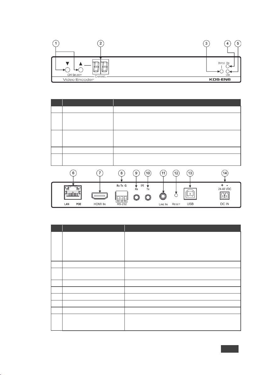
1
CH SELECT Buttons
Press the up or down arrow buttons to select the channel ID
2
CHANNEL Display
Displays the selected channel. If the channel number exceeds
appears as “°24”)
flashes for 5 seconds
4
ON LED
Flashes during power up and lights when on
5
LINK LED
On when a KDS-EN6 to KDS-DEC6 link is established and is
transmitting A/V signals
#
Feature
Function
6
LAN/POE RJ-45 Connector
Connect the KDS-EN6 to the network using
LAN LED
Green LED flashes during data transmission
POE LED
Orange LED lights when power is supplied
7
HDMI IN Connector
Connect an HDMI source
9
IR RX on a 3.5mm Mini Jack
Connect to a receiver
10
IR TX on a 3.5mm Mini Jack
Connect to an emitter
11
LINE In on a 3.5mm Mini Jack
Connect to an audio source
12
RESET Button
Press to reset KDS-EN6 to its default settings
(PN: 60-0009390)
3.1 Defining KDS-EN6
Figure 1: KDS-EN6 Video Encoder Front Panel
99, the 100 indicator turns on (for example, channel 124
3 STATUS LED Identifies a device in a system. When sending a P3K FIND-ME
Figure 2: KDS-EN6 Video Encoder Rear Panel
8 RS-232 (Rx,Tx,Gnd) Terminal
Block Connectors
13 USB Type B Port Connect to a USB host, for example, a PC
14 DC IN 24~48VDC Power
Terminal Block Connector
command to the system, the LED of the device to be identifi ed
recommended Kramer cables. Note that this port
supports power over Ethernet (PoE)
Connect to an RS-232 controller device (to control a
device on the decoder side)
Connect to the Kramer power adapter (DC voltage range
should be 24V to 48V), purchased separately
KDS-EN6, KDS-DEC6 - Overview
5
Page 11
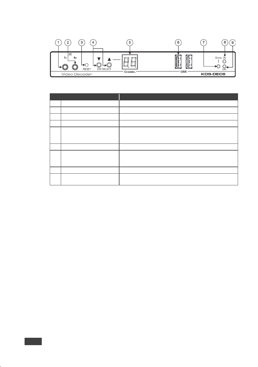
1
IR TX on a 3.5mm Mini Jack
Connect to an emitter
2
IR RX on a 3.5mm Mini Jack
Connect to a receiver
3
RESET Button
Press to reset KDS-DEC6 to its default settings
4
CH Select Buttons
Press the arrow buttons up or down to select the channel ID
exceeds 99, the 100 indicator turns on (for example, channel
125 appears as “° 25”)
6
USB Type A Ports (2)
Connect to a mouse and keyboard
7
STATUS LED
Identifies a device in a system. W hen sending a P3K
be identified flashes for 5 seconds
8
ON LED
Flashes during power up and lights when on
3.2 Defining KDS-DEC6
Figure 3: KDS-DEC6 Video Decoder Front Panel
# Feature Function
5 CHANNEL Display Displays the selected channel. If the channel number
FIND-ME command to the system, the LED of the device to
9 LINK LED
6 KDS-EN6, KDS-DEC6 - Overview
On when a KDS-EN6 to KDS-DEC6 link is established and
transmitting A/V si gnals
Page 12
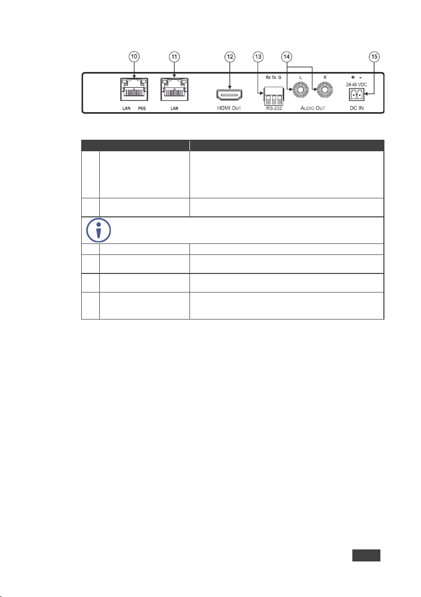
KDS-EN6
power over Ethernet (PoE)
POE LED
Orange LED lights when power is supplied
KDS-EN6 using the recommended Kramer cable.
12
HDMI Out Connector
Connect to an HDMI acceptor
13
RS-232 (Rx,Tx,Gnd) on
Connect to an RS-232 controlled device
14
L, R Audio on RCA
Connect to a powered speaker or an amplifier
Figure 4: KDS-DEC6 Video Decoder Rear Panel
# Feature Function
10 LAN/POE RJ-45
Connector
LAN LED Green LED flashes during data transmission
Connect the
recommended Kramer cable. Note that this port supports
to the network using the
11 LAN RJ-45 Connector
Use the LAN port (that is not used for connecting to the network or directly to the
encoder) to connect to the next KDS-DEC6 device in a daisy chain configuration
Terminal Block Connectors
Connectors
15 DC IN 24~48VDC Power
Terminal Block Connector
Connect the KDS-DEC6 to the network or directl y to the
Connect to the Kramer power adapter (DC voltage range
should be 24V to 48V), purchased separately
(PN: 60-0009390
KDS-EN6, KDS-DEC6 - Overview
7
Page 13

4 Initial Setup
Before installing the KDS-EN6/KDS-DEC6:
• Set a static IP address or set it automatically via DHCP.
• Set the channel number.
If the channel number exceeds 99, the indicator on the display lights.
The KDS-EN6 and KDS-DEC6 can be powered either via PoE (using the RJ-45
LAN/POE port) if available or via a 24-48V DC power adapter.
If 24-48V DC power is connected, PoE is disabled automatically.
KDS-EN6 and KDS-DEC6 IP address and channel number can be set using:
• The channel buttons on the KDS-EN6 / KDS-DEC6, see Section 4.1
.
• The embedded web pages, see Section 4.2.
4.1 Initial Setup via Channel Buttons
The initial setup includes setting the following:
• IP address
• Channel number
4.1.1 Setting the IP Address
To set the KDS-EN6 / KDS-DEC6 IP address via channel buttons:
1. Connect the KDS-EN6 / KDS-DEC6 LAN/POE RJ-45 port to your network (if
your network does not support PoE, connect a 24-48V DC power adapter).
The ON LED lights green and the LINK flashes (indicating that no streaming
activity is detected).
2. Press and hold for 3 seconds.
3. Press or to select DH (DHCP) or SC (static) IP address setup.
8 KDS-EN6, KDS-DEC6 - Initial Setup
Page 14

4. If you selected DHCP (for Static, go to the next step):
For KDS-DEC6, press and hold or for 3 seconds to save your
selection.
The channel display flashes “--” 3 times and the device reboots.
For KDS-EN6, the channel display flashes “ID” 3 times.
Continue to set the channel number for the KDS-EN6.
When setting to DHCP we recommend that you contact your IT
administrator for setting the system IP addresses.
5. If you selected Static, press and hold or for 3 seconds to save your
selection.
The channel display flashes “IP” 3 times and the device reboots.
6. Press or to set the IP address.
You can only define the last three digits of the IP address when setting
the IP address via the channel buttons. To change the entire IP
address, go to Section 4.2.1
7. Press and hold and for 3 seconds to save your selection.
).
4.1.2 Setting the Channel Number
The KDS-DEC6 channel number is set by simply pressing the or buttons at
any time.
The KDS-EN6 channel number can be set immediately after the IP address is set
(via either static or DHCP).
To set the channel number for the encoder:
KDS-EN6, KDS-DEC6 - Initial Setup
1. Wait until the channel display flashes “ID” 3 times.
2. Press or to select the channel number.
3. Press and hold and for 3 seconds to save your selection.
The channel display flashes “--” 3 times and the device reboots.
9
Page 15

4.1.3 Viewing the IP Address and Channel Number
You can view the current IP address and channel number any time.
To view the IP address and channel number:
1. Press and hold for 3 seconds.
2. The channel display shows “IP” for 3 seconds and then shows the IP
address for 3 seconds followed by the channel number.
4.2 Initial Setup via Web Pages
Use the web pages to set the:
• IP address, see Section 4.2.1
.
• Channel numbers, see Section 4.2.2.
4.2.1 Setting the IP Address via Web Pages
Using the embedded web pages you can change the entire IP address.
To set the IP address:
1. Connect the KDS-EN6 / KDS-DEC6 Ethernet port to the Network and power
the device (either by using the power adapter or via PoE).
2. Access the embedded Web pages (see Section 6
3. In the Network tab (see Section 6.3) select the IP mode.
4. If you selected Static, type in the IP address.
When setting to DHCP we recommend that you contact your IT
administrator for setting the system IP addresses.
5. Click Apply and reboot the device.
4.2.2 Setting the Channel Number via Web Pages
).
Use API commands to set channel numbers.
10 KDS-EN6, KDS-DEC6 - Initial Setup
Page 16

A KDS-EN6 channel number usually remains constant during normal
operation. However, a KDS-DEC6 channel number must be modified
according to the channel number of the currently linked encoder (for
example, in a matrix configuration). This enables linking to different
encoders in the network
To set the channel number:
1. Connect the KDS-EN6 / KDS-DEC6 Ethernet port to the Network and power
the device (either using the power adapter or via PoE).
2. Access the embedded Web pages (see Section 6
).
3. In the System tab select Utilities (see Section 6.1.3).
4. In the Console API Command text box enter the following command:
For the KDS-EN6:
"astparam s multicast_ip 225.0.100.X; astparam s
hostname_id 000X; astparam s reset_ch_on_boot n;
astparam save;"
where X=Channel number, for example:
for multicast_ip: 225.0.100.8 or 225.0.100.10
for hostname_id: 0008 or 0010
Click Apply.
Power cycle the device
For the KDS-DEC6:
"Switchto X"
where X=Channel number
Click Apply.
API commands can also be entered directly via Telnet. The default is
Telnet port 24. Use "root" to log in. No password is required.
KDS-EN6, KDS-DEC6 - Initial Setup
11
Page 17

then switch on the power to each device.
5 Connecting the KDS-EN6 and KDS-DEC6
Always switch off the power to each device before connecting it to your
KDS-DEC6. After connecting your KDS-DEC6, connect its power and
Before connecting the KDS-EN6 and KDS-DEC6 note that:
• When connecting KDS-EN6 to KDS-DEC6 via the Ethernet, use a 1 Giga
LAN switch and make sure that jumbo frame (over 8k) and IGMP snooping
are enabled.
• The BC-UNIKAT cable length connecting KDS-EN6/KDS-DEC6 to the
network should not exceed 330 feet (100m).
• The KDS-EN6 operates with a default EDID. If you need to copy the EDID
from the acceptor, do so via the Web pages.
Following the initial setup (see Section 4
KDS-DEC6 devices in any of the following ways:
• Unicast setup: single encoder-decoder unicast connection, see Section 5.1.
• Multicast configuration setup: a multicast setup can include any of the
following configurations:
One encoder to many decoders, see Section 5.2
Many encoders to many decoders (matrix switcher configuration), see
Section 5.3
Video wall configuration, see Section 5.4.
• KVM (Keyboard, Video, Mouse) setup: many encoders to a single decoder
see Section 5.5
12 KDS-EN6, KDS-DEC6 - Connecting the KDS-EN6 and KDS-DEC6
.
.
), you can configure the KDS-EN6 and
.
Page 18

connect its power and then switch on the power to each device.
5.1 KDS-DEC6/KDS-EN6 Unicast Installation
You can use one KDS-EN6 device and one KDS-DEC6 device to configure an
encoder and decoder system (see Figure 5
The encoder and decoder devices can be connected directly or via LAN.
Always switch off the power to each device before connecting it to your
KDS-DEC6/KDS-EN6. After connecting your KDS-DEC6/KDS-EN6,
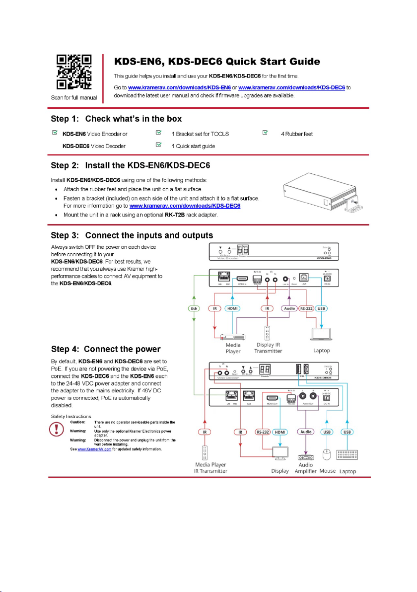
To connect the encoder and decoder system as shown in the example in
Figure 5
:
1. On the KDS-EN6, connect an HDMI source (for example, a media player) to
the HDMI IN connector.
2. On the KDS-DEC6, connect the HDMI OUT connector to an HDMI acceptor
(for example, a display).
3. Connect the LAN RJ-45 connector on the KDS-DEC6 directly to the LAN
RJ-45 connector on the KDS-EN6 using an Ethernet cable (or via LAN).
4. If you are not powering the device via PoE, connect the KDS-DEC6 and the
KDS-EN6 to the 24-48V DC power adapter and connect the adapter to the
mains electricity (not shown in Figure 5
).
).
5. If required, connect a PC and/or controller to the RS-232 terminal block
connector on the KDS-EN6.
6. If required, connect the USB ports:
On the KDS-EN6 connect a PC to the USB type B port.
On the KDS-DEC6 connect a mouse and a keyboard to the two USB
type A ports.
7. If required, connect an unbalanced stereo audio source to the
KDS-EN6 (for example, the media player’s audio signal) and an unbalanced
stereo audio acceptor (for example, speakers) to the KDS-DEC6.
You do not have to use all the possible control options.
KDS-EN6, KDS-DEC6 - Connecting the KDS-EN6 and KDS-DEC6
13
Page 19

8. If requird, control the media player connected to KDS-EN6 from the decoder
side via IR:
On the KDS-DEC6, connect a Kramer External IR Sensor cable to the IR
Rx 3.5mm mini jack.
On the KDS-EN6, connect a Kramer IR Emitter cable to the IR Tx 3.5mm
mini jack and attach the emitter to the IR receiver on the media player.
The media player’s remote control sends a command while pointed at the
External IR Sensor. The IR signal passes through the ETH cable and the IR
Emitter to the media player. The media player responds to the command.
9. If required, control the display connected to KDS-DEC6 from the encoder
side via IR:
On the KDS-EN6, connect a Kramer External IR Sensor cable to the IR
Rx 3.5mm mini jack.
On the KDS-DEC6, connect a Kramer IR Emitter cable to the IR Tx
3.5mm mini jack and attach the emitter to the IR receiver on the display.
The display remote control sends a command while pointed at the External
IR Sensor. The IR signal passes through the ETH cable and the IR Emitter
to the display. The display responds to the command.
IR signals can be passed only between linked devices.
10. If required, control the display connected to KDS-EN6 from the decoder side
via RS-232:
Connect an RS-232 cable from the laptop to the RS-232 terminal block
connector on the KDS-DEC6.
On the KDS-EN6, connect the RS-232 terminal block connector to the
RS-232 port on the display.
RS-232 bidirectional signals can be sent between the display and the laptop
connected to the KDS-EN6.
14 KDS-EN6, KDS-DEC6 - Connecting the KDS-EN6 and KDS-DEC6
Page 20

KDS-DEC6.
Figure 5: Connecting an Encoder and Decoder S ystem
When connecting the encoder-decoder system over the network, connect
the LAN-PoE RJ-45 port on the KDS-EN6 to the Ethernet and on the other
side connect the Ethernet to the LAN-PoE/Lan RJ-45 port on the
KDS-EN6, KDS-DEC6 - Connecting the KDS-EN6 and KDS-DEC6
15
Page 21

5.2 One-to-Many Configuration
You can set one encoder to several decoders in one of the following ways:
• One-to-many via LAN switcher: one encoder is connected to the input of a
LAN switch and its outputs are connected to the decoders, see Section 5.2.1
• One-to-many via daisy chain: one encoder is connected to a decoder and
all the other decoders are daisy chained to the first decoder, see
Section 5.2.2
5.2.1 One-to-Many via LAN Switcher
In this configuration, the source video is streamed via the LAN switch and appears
on all the displays.
The one-to-many configuration consists of one encoder that connects to a LAN
switch and several decoders that connect to the LAN switch output. A display is
connected to the output of each decoder.
Configure the devices:
• Verify that the KDS-EN6 and KDS-DEC6 devices each are set with a unique
IP address (see Section 4
.
).
.
• Set all the devices to the same channel number.
5.2.1.1 Mounting the System
Figure 6: Connecting a One-to-Many System
16 KDS-EN6, KDS-DEC6 - Connecting the KDS-EN6 and KDS-DEC6
Page 22

5.2.2 One to Many via Daisy Chain
In this configuration, the source video is streamed via the encoder to the first
decoder and the next decoders are daisy-chained to the first decoder via the
second LAN port. A display is connected to the output of each decoder.
Configure the devices:
• Verify that the KDS-EN6 and KDS-DEC6 devices each are set with a unique
IP address (see Section 4
• Set all the devices to the same channel number.
).
Figure 7: Connecting a Daisy-Chain System
5.3 Matrix Configuration
In this configuration, several source videos are streamed via the LAN switch and
are routed to the linked decoders.
The many-to-many configuration consists of several encoders that connect to a
LAN switch together with several decoders. A display is connected to the output of
each decoder.
Configure the Devices:
• Verify that the KDS-EN6 and KDS-DEC6 devices each are set with a unique
IP address (see Section 4
• Set each encoder to a unique channel number and change the decoder
channel numbers according to the desired link to an encoder.
KDS-EN6, KDS-DEC6 - Connecting the KDS-EN6 and KDS-DEC6
).
17
Page 23

Figure 8: Connecting the KDS-EN6, KDS-DEC6 Video Encoder
5.4 Video Wall Setup
In the video wall setup, one encoder transmits a signal to a series of decoders
creating a video wall configuration.
The video wall configuration consists of an encoder that connects to a LAN switch
input and a series of decoders (connected to the LAN switch output) that together
make up the video wall. Each screen on the video wall is connected to the HDMI
output of one decoder.
The KDS-EN6 and KDS-DEC6 units are each defined by their location in the video
wall layout. Each KDS-EN6 is assigned a row number and defined by row number
and position in the row. The position definition is unique and is usually defined
once during the basic setup.
The PC controller can be connected via LAN to control the encoders and decoders
that make up the video wall.
Video wall setup includes three basic steps:
• Mounting the video wall
• Setting up the devices
• Configuring the video wall
18 KDS-EN6, KDS-DEC6 - Connecting the KDS-EN6 and KDS-DEC6
Page 24

5.4.1 Mounting the Video Wall
Before mounting the video wall, verify that each device (encoder and decoders)
has a unique IP address (see Section 4.1.1
Always switch off the power to each of the peripheral devices before
connecting it to your KDS-DEC6 / KDS-EN6. After connecting your
KDS-DEC6 / KDS-EN6, connect its power and then switch on the
power to each device.
To configure a video wall (for example, a 3x3 video wall):
1. Connect an HDMI source (for example, a media player) to the KDS-EN6
HDMI IN connector.
2. Connect the KDS-EN6 LAN/PoE RJ-45 port to the RJ-45 connector on a
LAN switch.
3. Connect the RJ-45 ports on the LAN switch to nine KDS-DEC6 units.
4. Connect the HDMI OUT connector on each KDS-DEC6 device to a display
(9 displays altogether).
).
5. Position the displays in a 3x3 video wall setup.
6. Check that all the system components are connected correctly.
7. Power the system.
KDS-EN6, KDS-DEC6 - Connecting the KDS-EN6 and KDS-DEC6
19
Page 25

Figure 9: Video Wall Setup
20 KDS-EN6, KDS-DEC6 - Connecting the KDS-EN6 and KDS-DEC6
Page 26

5.4.2 Setting Up the Devices
To configure the video wall devices:
1. Open your Internet browser.
2. Type the actual IP address of the device in the address bar of your browser.
For example:
3. In the Functions tab, check Enable Video Wall (see Section 6.4.1).
4. In the Network tab, set the Casting Mode to Multicast (see Section 6.3.2).
5. Select the Video Wall tab.
6. In Basic Setup, set the Bezel and Gap Compensation (see Section 6.2.1.1
7. Set the Wall Size and Position Layout.
8. Open the Apply To drop down box. Select the Client device to which you
want to assign the position.
You do not have to open a new web page per device.
9. Repeat this procedure for all the video wall decoders in the video wall.
).
KDS-EN6, KDS-DEC6 - Connecting the KDS-EN6 and KDS-DEC6
21
Page 27

5.5 KVM Setup
In this configuration, on the decoder side, a keyboard and a mouse are connected
to the USB ports and a display is connected to the HDMI output. On the encoder
side, each encoder is connected to a PC via the USB and HDMI ports.
Configure the Devices:
• Verify that the KDS-EN6 and KDS-DEC6 devices each are set with a unique
IP address (see Section 4
• Set each encoder to a unique channel number and change the decoder
channel numbers according to the desired link to an encoder.
).
Figure 10: KVM Setup
22 KDS-EN6, KDS-DEC6 - Connecting the KDS-EN6 and KDS-DEC6
Page 28

255.255.0.0.
6 Using the Embedded Web Pages
The KDS-EN6 / KDS-DEC6 Web pages let you configure and control KDS-EN6
and KDS-DEC6 operation via the Ethernet. Connect the Ethernet port of the
KDS-EN6 / KDS-DEC6 to the web and type the IP address of
KDS-EN6 / KDS-DEC6 to access the web pages.
The KDS-EN6 / KDS-DEC6 web pages enable performing the following:
• Modifying and viewing the system, see Section 6.1
• Setting up the video wall, see Section 6.2.
• Setting up the network, see Section 6.3.
• Setting up operation functions, see Section 6.4.
Note that the computer IP address should be set to same domain name
as HD over IP, such as 169.254.1.11, and that subnet mask set to
6.1 Modifying and Viewing the System
The System tab enables performing the following:
• Viewing system version information, see Section 6.1.1
• Updating the firmware, see Section 6.1.2.
• Setting system utilities, see Section 6.1.3.
• Resetting to factory default, see Section 6.1.3.1.
• Viewing system statistics, see Section 6.1.4.
.
.
KDS-EN6, KDS-DEC6 - Using the Embedded Web Pages
23
Page 29

6.1.1 Viewing System Version Information
Click the Version Information line to view the version detail information:
Figure 11: The System Tab – Version Information
24 KDS-EN6, KDS-DEC6 - Using the Embedded Web Pages
Page 30

6.1.2 Updating the Firmware
To update the firmware:
1. In the System tab, select Update Firmware.
Figure 12: The System Tab – Firmware upgrade
2. Click Choose File, select firmware file version from the list and click OK.
Figure 13: The System Tab – selecting the Firmware File
KDS-EN6, KDS-DEC6 - Using the Embedded Web Pages
25
Page 31

to open the file window
To cancel this operation click Choose File again
and click Cancel.
3. Click Upload and wait for the completion of the update process to finish.
6.1.3 Setting System Utilities
To update the firmware:
1. In the System tab, select Utilities.
Figure 14: The System Tab – Utilities for KDS-DEC6
2. Perform the following actions:
Click Factory Default to reset to factory default values (see
Section 6.1.3.1
).
Click Reboot to reboot the system.
Type an API command via Console API Commands text box and click
Apply to send the command to a peripheral device, and see the reply in
the Output box.
26 KDS-EN6, KDS-DEC6 - Using the Embedded Web Pages
Page 32

For the KDS-EN6 you can also reset the EDID to a selected default value and
then click Apply.
Figure 15: The System Tab – Utilities Window for KDS-EN6
KDS-EN6, KDS-DEC6 - Using the Embedded Web Pages
27
Page 33

6.1.3.1 Resetting to Factory Default
Click Factory Default to reset the device to its default values (see Figure 15).
Following a factory reset, the current IP address returns to its default value. You
cannot access the Web pages using the last known IP address. The default IP
address can be found on the connected display or by using IP address detection
software, such as Kramer K-Upload.
Following a factory reset, set the casting mode to multicast if changed.
Factory reset does not reset the EDID.
28 KDS-EN6, KDS-DEC6 - Using the Embedded Web Pages
Page 34

6.1.4 Viewing System Statistics
System statistics include the KDS-EN6 / KDS-DEC6 machine status, network,
video information including EDID information (only for the encoder) and display
information.
Figure 16: The System Tab – Utilities, Machine State and Network Information
KDS-EN6, KDS-DEC6 - Using the Embedded Web Pages
29
Page 35

For KDS-EN6, the EDID information also appears:
Figure 17: The System Tab – Utilities, Video Information
30 KDS-EN6, KDS-DEC6 - Using the Embedded Web Pages
Page 36

6.2 Setting the Video Wall
A video wall consists of several screens that are tiled together to form a single
large display. Each display in the video wall is connected to a KDS-DEC6 device
and needs to be configured according to its specific location on the video wall. The
position definition is unique and is usually defined once during the basic setup.
You can setup the KDS-EN6 / KDS-DEC6 video wall, via the Video Wall tab, for
each device (encoder or decoder) from the Web page of any one of the video wall
encoder/decoder devices.
KDS-EN6, KDS-DEC6 - Using the Embedded Web Pages
31
Page 37

6.2.1 Basic Setup
Use the basic setup to configure the video wall.
To configure the video wall:
1. In the Video Wall tab, select Basic Setup.
Figure 18: The System Tab – Video Wall, Basic Setup
32 KDS-EN6, KDS-DEC6 - Using the Embedded Web Pages
Page 38

2. Set the following:
Set the bezel and gap compensation in 0.1mm units (this is usually the
same for all the video wall displays), see Section 6.2.1.1
Set the Vertical Monitor Count (the number of rows) and the Horizontal
Monitor Count (the number of columns) to define the size of the video
wall, see Section 6.2.1.2
.
Set the row position and column position of a specific decoder in the
video wall layout, see Section 6.2.1.2
.
If required, set the stretch type (Fit In or Stretch Out), see Section 6.2.1.3.
If required, rotate the image, see Section 6.2.1.3
Enable OSD for the selected device, see Section 6.2.1.3.
3. When the basic setup is complete, select the device to which the setup
applies (this, any other device or all the devices) and click Apply.
.
Figure 19: The System Tab – Video Wall, Applying the Basic Setup to a Device
4. Repeat the basic setup for each device in the video wall.
KDS-EN6, KDS-DEC6 - Using the Embedded Web Pages
33
Page 39

#
Function
OW
Set the display outside width
OH
Set the display outside height
VW
Set the screen viewable width
VH
Set the screen viewable height
#
Function
Vertical Monitor Count
Set the number of vertical displays in the video wall
Horizontal Monitor Count
Set the number of horizontal displays in video wall
Row Position
Set the row in which the specific display is positioned
Column Position
Set the column in which the specific display is positioned.
#
Function
Stretch type
Select Stretch Out to keep the aspect ratio of the original video
Select Fit In to auto adjust aspect ratio to fit the screen
Clockwise Rotate
Rotate the video to 0, 180 or 270 degrees
Show OSD
Check to show the position number of the display on screen.
6.2.1.1 Setting the Bezel and Gap Compensation
Set the display and screen sizes (width and height) for bezel and gap
compensation. If you do not need this calculated, set all values to 0.
When setting bezel and gap compensation, a value of 1 equals 0.1mm.
You can only enter whole numbers.
6.2.1.2 Wall Size and Position Layout
Define the wall size and layout:
Each specific display is defined by the IP address of the KDS-DEC6
device to which it is connected.
6.2.1.3 Preferences
Set the video wall preferences:
source.
The position number can help you to identify the screen position in
the video wall
6.2.2 Advanced Setup
The basic setup is usually sufficient for setting the video wall layout. However, you
can choose a specific device/column/row in the video wall layout.
34 KDS-EN6, KDS-DEC6 - Using the Embedded Web Pages
Page 40

Figure 20: Video Wall Tab – Advanced Setup, Selecting a specific Device, Column or Row
To set a Specific device, column or row:
1. In the Video Wall tab, select Advanced Setup.
2. Perform the following changes:
Reset it to the basic setup (as defined in Section 6.2.1
Set the stretch type and rotation.
Change the screen layout (the number of columns and rows).
Change the position of the device/column/row.
Shift the image vertically or horizontally
Scale the image up horizontally and vertically.
Send an API command
KDS-EN6, KDS-DEC6 - Using the Embedded Web Pages
).
35
Page 41

Figure 21: Video Wall Tab – Advanced Setup Configuration
3. Click Apply to any change you make.
36 KDS-EN6, KDS-DEC6 - Using the Embedded Web Pages
Page 42

6.3 Setting Up the Network
The Network tab enables you to set the IP mode and address and set the casting
mode.
6.3.1 IP Setup
The network parameters (IP address, subnet mask and default gateway can be set
via one of the three different IP modes:
• Auto IP: the IP address is assigned randomly
• DHCP: the DHCP server assigns the IP address
• Static: type the IP Address manually
Figure 22: Network Tab – IP Setup
6.3.2 Casting Mode
Set the Casting mode to Multicast or Unicast. A Multicast transmission sends IP
packets to a group of hosts on a network. A Unicast stream transmits IP packets to
a single destination IP address
KDS-EN6 and KDS-DEC6 should be set to the same Casting Mode.
We recommend that you set the system to multicast mode for it is
applicable to both one-to-multi or multi-to-multi applications.
KDS-EN6, KDS-DEC6 - Using the Embedded Web Pages
37
Page 43

Figure 23: The Network Tab – Casting Mode
Check Auto select USB operation mode per casting mode for USB operation to
follow the casting mode.
6.4 Setting the Operation Functions
Use the function tabs to set the encoder/decoder system functionality before
activation.
Set the functionality of:
• Video signal over IP, see Section 6.4.1
.
• USB over IP, see Section 6.4.2.
• Serial signal over IP, see Section 6.4.3.
6.4.1 Video over IP Behavior
Set the video behavior over IP.
Setup is slightly different for the encoder and decoder.
For both encoder/decoder check Enable Video over IP and/or Enable Video
Wall, if required.
38 KDS-EN6, KDS-DEC6 - Using the Embedded Web Pages
Page 44

6.4.1.1 KDS-DEC6 Setup
Perform the following and then click Apply:
• Select this specific device from which the encoder copies the EDID.
When checked, KDS-DEC6 sends the display EDID to KDS-EN6. The new
EDID is saved to KDS-EN6 and remains even if KDS-DEC6 is disabled.
• Set the scaler output mode: Pass-Through, Auto Detect, Full HD 1080p60,
Full HD 1080p50, Ultra HD 2160p30 or Ultra HD 2160p25.
• Set the time out for video loss and define screen behavior after video signal
loss: Set the time for the system to keep the latest video image after video
loss detection. When enabled, KDS-DEC6 turns off the display following video
signal loss.
Figure 24: Functions Tab – Video over IP for KDS-DEC6
KDS-EN6, KDS-DEC6 - Using the Embedded Web Pages
39
Page 45

6.4.1.2 KDS-EN6 Setup
Perform the following and then click Apply:
• Select the maximum bit rate if there is a total throughput limit on the network.
Note that limiting the maximum bit rate may the affect video quality.
• Set the maxim um frame rate. If the frame rate is too low the video will not
appear continuous.
Figure 25: The Functions Tab – Video over IP for KDS-EN6
40 KDS-EN6, KDS-DEC6 - Using the Embedded Web Pages
Page 46

6.4.2 USB over IP
Set the USB over IP behavior of the encoders/decoders before activating the
system.
Figure 26: The Functions Tab – USB over IP for KDS-DEC6
Check Enable USB over IP to enable USB transmission over the Ethernet cable
and then Set the:
• Operation Mode, select one of the following operation modes:
Auto select – the operation mode is automatically selected according to
the network casting mode selection (see Section 6.3.2
Active on Link – (unicast network default) in the unicast mode, once a
connection (link) is established, USB connectivity is enabled.
Active per request – (multicast network default) in the multicast mode,
whoever moves the mouse gets the token. When not active, another USB
device can take the token and become active.
KDS-EN6, KDS-DEC6 - Using the Embedded Web Pages
).
41
Page 47

• Compatibility Mode, check the following:
K/M over IP – uncheck if mouse, keyboard or touch panel are not working
as expected.
In order to manually enable/disable keyboard or mouse devices
connected to the USB ports, the following commands can be used after
unchecking this option and restarting the device:
ast_send_event -1 e_start_usb
ast_send_event -1 e_stop_usb
For more information refer to the KDS-EN6, KDS-DEC6 API Guide
available at www.kramerav.com/downloads/KDS-DEC6
Mouse not responding well – (KDS-EN6 only) check if the cursor moves
slowly or unexpectedly.
.
Figure 27: The Functions Tab – USB over IP for KDS-EN6
42 KDS-EN6, KDS-DEC6 - Using the Embedded Web Pages
Page 48

6.4.3 Serial over IP
Set the serial over IP behavior:
Figure 28: The Functions Tab – RS-232 over IP
Set the following:
• Enable Serial over IP: check to enable serial transmission over the Ethernet
cable. When unchecked, serial transmission via network is disabled.
Setting this function differently for devices in the system may affect the
video quality.
• Operation Mode, select an operation mode: Type 1, Type 2 or type 2 guest
mode:
Type 1 – (dynamic baud rate) KDS-DEC6 RS-232 baud rate is
configurable via special RS-232 commands. Redirection is controlled by
the PC RS-232 connected to the KDS-EN6. Use a fixed baud rate
(115200,8,none,1) The connection can be dynamically changed.
Applies to: HDMI Multicast TV Broadcast system that requires display
control.
Type 2 – (static baud rate) RS-232 redirection is automatically
established between encoders and decoders. There is no need to
explicitly issue commands for establishing redirection.
The FW code automatically links the host and clients all together using a
preconfigured baud rate setting (default is 115200,8,n,1). Normally, this
KDS-EN6, KDS-DEC6 - Using the Embedded Web Pages
43
Page 49

static baud rate setting is preconfigured on manufacturing. The baud rate
setting can be changed by "Console API".
Applies to: a multicast system with touch panels on the client sides that
need communication with the PC on the host side.
Type 2 Guest mode: designed for controlling UART port 1 through a
controller (for example, PC) that is connected to the network. Both Type1
and Type2 are supported.
• Baud Rate Setting: set RS-232 format in this area. KDS-EN6 and
KDS-DEC6 should have the same baud rate format.
Go to Section 7.1
over IP.
for detailed instructions on how to setup serial communication
44 KDS-EN6, KDS-DEC6 - Using the Embedded Web Pages
Page 50

7 Operating the KDS-EN6 and KDS-DEC6
After connecting your KDS-EN6/ KDS-DEC6 units, we recommend that you
validate your connection setup, network discovery, and the quality of your audio
and video sources before you continue.
7.1 Setting Up RS-232 over IP
RS-232 signals pass via the system to and/or from the peripheral devices that are
connected to the decoders via a controller that is connected on the encoder side.
Select the connection type according to your requirements (see Section 6.4.3
7.1.1 Type 1 Setup
In the Type 1 setup, RS-232 redirection is set and controlled by an RS-232
command.
In the following example, a system of two encoders and two decoders is
connected via a LAN switch. A laptop is connected to KDS-EN6 1 and a display is
connected to each of the two KDS-DEC6 devices. The baud rate of the displays is
different to that of KDS-EN6 1.
).
Figure 29: Serial over IP – RS-232 over IP
KDS-EN6, KDS-DEC6 - Operating the KDS-EN6 and KDS-DEC6
45
Page 51

Note that:
• The RS-232 settings of the encoders should always be 115200-8n1.
• The RS-232 setting of the RS-232 controller (the laptop) should always be
115200-8n1.
To send an RS-232 command from the PC to the display on KDS-DEC6 1:
1. Verify that both encoders and decoders enable serial over IP and are set to
Type 1 operation mode.
Figure 30: Serial over IP – Type 1 Operation Mode
2. On your PC, open HyperTerminal and press Ctrl+N.
3. Type the KDS-DEC6 1 open command:
“ast_c 0019fa0051b3 9600-8n1” (the MAC address of the device and the
RS-232 settings of the display).
4. Press Enter.
KDS-EN6 1 RS-232 signal is redirected to KDS-DEC6 1 and you can control
the display on KDS-DEC6 1 via your PC.
5. To stop redirection, press Ctrl+N.
46 KDS-EN6, KDS-DEC6 - Operating the KDS-EN6 and KDS-DEC6
Page 52

7.1.2 Type 2 Setup
In the Type 2 setup, RS-232 redirection is performed automatically you just need
to verify the following:
• The encoders and decoders in the system are all linked.
• RS-232 can be passed over IP.
In the following example, a system of two encoder and two decoders is connected
via a LAN switch. A laptop is connected to KDS-EN6 and a touch panel is
connected to each of the two KDS-DEC6 devices. The baud rates of the touch
panels are set to the same common lowest value for each device on the system.
Figure 31: Serial over IP – Type 2 connection
KDS-EN6, KDS-DEC6 - Operating the KDS-EN6 and KDS-DEC6
47
Page 53

To detect an RS-232 signal sent from a touch panel to the PC:
1. Verify that both encoders and decoders enable serial over IP and are set to
Type 2 operation mode.
2. Set all encoders and decoders to the common lowest baud rate value.
For example, if the encoder is set to 115200 but the touch panels’ baud
rates are 9600, set the baud rate to 9600 for all the devices in the system
that requires RS-232 communication.
Figure 32: Serial over IP – Type 2 Operation Mode
3. On your PC, open HyperTerminal and set the PC baud rate to 9600.
48 KDS-EN6, KDS-DEC6 - Operating the KDS-EN6 and KDS-DEC6
Page 54

7.1.3 Guest Type 2 Mode Setup
Use guest type 2 for RS-232 communication with the peripheral devices on the
encoders-decoders system via a controller that is connected to the network.
In this example, two encoders and two decoders are connected to a LAN switch
and a laptop is connected to the network.
Figure 33: Serial over IP – Type 2 Guest connection
To send an RS-232 command from the PC to the display on KDS-DEC6 2:
1. Verify that both encoders and decoders enable serial over IP and are set to
Type 2 Guest operation mode.
Figure 34: Serial over IP – Type 2 Guest Operation Mode
KDS-EN6, KDS-DEC6 - Operating the KDS-EN6 and KDS-DEC6
49
Page 55

2. On your PC open the HyperTerminal and then press Ctrl+N.
3. Set the baud rate to 115200-8n1.
4. Use the Telnet utility to connect to the box’s port 6752 (169.254.3.2.6752).
The laptop can pass RS-232 data to KDS-DEC6 2.
7.2 Setting Up USB over IP
For detailed instructions, see Section 6.4.2 and Section 5.5.
7.3 Setting Up IR over IP
You can control the peripheral devices remotely using IR over IP. For example you
can control the media player from the display side by pointing the media player IR
remote controller toward the IR receiver connected on the KDS-DEC6 side,
see Figure 5
.
The IR signal can only be extended between linked units.
7.4 Fast Video Switching
To optimize switching time, verify that:
• All the encoders and decoders in the system have the same firmware version.
• The current video streaming source and the new video streaming source
have:
The same resolution, refresh rate, and scanning mode
(interlace/progressive mode)
Switching from HDMI to HDMI or HDMI to DVI
The same HDCP mode
The same HDMI info frame and “Video quality table”
50 KDS-EN6, KDS-DEC6 - Operating the KDS-EN6 and KDS-DEC6
Page 56

7.5 Resetting the KDS-EN6/ KDS-DEC6 to Factory Default Values
You can reset the devices to their factory default values via the embedded Web
pages (see Section 6.1.3.1
1. Power down the device.
2. Press and hold the down button for 10 seconds while powering the device.
3. The device powers up and after 5 to 8 seconds resets back to factory default
values.
) or by using the channel buttons on the device:
KDS-EN6, KDS-DEC6 - Operating the KDS-EN6 and KDS-DEC6
51
Page 57

KDS-EN6
KDS-DEC6
Inputs:
1 HDMI connector,
1 IR on 3.5mm mini jacks (Rx)
1 Ethernet (LAN / PoE) on an
Outputs:
1 Ethernet (LAN / PoE) on an
1 HDMI connector
connector (daisy-chain LAN),
Network :
10M/100M/1000M
Network Switch:
1G Multicast, IMGP Snooping Non-blocking, Layer 2
Streaming:
Unicast and multicast through RTSP (Real Time Streaming
IR:
Wide-band 20kHz~60kHz bidirectional IR transmission
Management:
API, Kramer Control, Kramer AV services (Powered by Kramer
Network )
Video Encoding/Decoding:
Compression Standard:
MJPEG
HDCP
HDCP 2.2
on the decoder output
250Mbps
8 Technical Specifications
1 unbalanced stereo audio on a
3.5mm mini jack (line in)
1 RS-232 on terminal block
connectors
1 USB (type B) port
RJ-45 connector
1 IR on 3.5mm mini jacks (Tx)
Protocol)
Controls: Reset button, up and down channel buttons, channel 7-segment
display, STATUS, LINK and ON LEDs
Scaling and Cropping: Built in scaling and cropping for flexible display of source content
Bit Rates: 4K Peak: 850Mbps; 4K Average: 350Mbps; 1080p Average:
RJ-45 connector
1 IR on 3.5mm mini jacks Rx
2 left and right unbalanced
stereo audio on RCA
connectors
1 RS-232 on terminal block
connectors
2 USB (type A) ports
1 IR on 3.5mm mini jacks (Tx)
1 Ethernet on an RJ-45
Resolution: 4096x2160@60Hz, 3840x2160@60Hz, 1920×1200@60Hz,
52 KDS-EN6, KDS-DEC6 - Technical Specifications
1920×1080@60Hz, 1864x1050@60Hz, 1856x1392@60Hz,
1792x1344@60Hz, 1728x1080@60Hz, 1704x960@60Hz,
1680×1050@60Hz, 1600×1200@60Hz, 1600x1050@60Hz,
1600×900@60Hz, 1536x960@60Hz, 1440×900@60Hz,
1440x576@60Hz, 1440x480@60Hz, 1400×1050@60Hz,
1366x768@60Hz,1360×768@60Hz, 1280×1024@60Hz,
1280×960@60Hz, 1280x800@60Hz, 1280x768@60Hz,
1280×720@60Hz,1224x768@60Hz, 1152x864@60Hz,
1152x720@60Hz, 1024×768@60Hz, 1064x600@60Hz,
1024x384@60Hz, 960x600@60Hz, 848x480@60Hz,
800×600@60Hz, 768x480@60Hz, 720×576@60Hz,
720×480@60Hz, and 640×480@60Hz, 640x400@60Hz,
640x350@60Hz
Page 58

KDS-EN6
KDS-DEC6
Audio Encoding/Decoding:
Compression Standard
(Analog In/Out):
AAC-LC
Channels (HDMI
PCM 2, 5.1, 7.1 Channel, Dolby Digital 5.1 Channel, Dolby Digital
High Resolution, DTS-HD Master Audio
Power Options:
PoE, External power supply
Power Consumption:
48V DC, 140mA max.
48V DC, 185mA ma x.
Operating Temperature:
0° to +40°C (32° to 104°F)
Storage Temperature:
-40° to +70°C (-40° to 158°F)
Humidity:
10% to 90%, RHL non-condensing
Dimensions:
19cm × 10.3cm × 2.3cm (7.48" × 4.06" × 0.91") W, D, H
Shipping Dimensions:
34.5cm × 16.5cm × 5.2cm (13.58" × 6.5" × 2.05") W, D, H
Weight:
0.55kg (1.2lbs) approx.
Shipping Weight:
0.782kg (1.7lbs) approx.
Options:
IR Cable (PN: 3500-900617); External DC Power Supply
(PN: 60-0009390)
Specifications are subject to change without notice at www.kramerav.com
embedded Audio):
Plus, Dolby Digital True-HD,DTS 5.1 Channel, DTS-ES, DTS-HD
KDS-EN6, KDS-DEC6 - Technical Specifications
53
Page 59

Page 60

For the latest information on our products and a list of Kramer distributors, visit
our Web site where updates to this user manual may be found.
We welcome your questions, comments, and feedback.
Web site:
E
SAFE TY WARNING
Disconnect the unit fro m the power
supply before opening and servicing
P/N:
2900-300655
Rev:
2
!
www.kramerav.com
-mail: info@kramerav.com
 Loading...